Advertisement
Quick Links
Normally-Closed Output
Output will stay ON by default and turn OFF when
you activate it. To toggle this option, power-up
holding the REC button for a few seconds.
Write Protect
Recording animation will be disabled if this option is
enabled. To toggle this option, power-up holding the
1/Play button for a few seconds.
Factory Reset
Power up holding BOTH buttons for a few seconds to
reset to factory defaults.
Determining Current Settings
At startup the current settings will be shown on the LED.
See the table below to find the pattern you see.
Settings - Status LED Pattern at Startup
It'll start with one of these blink patterns
Default (Write-Protect and Normally-Closed Output are disabled)
Normally-Closed output enabled
Write-Protect enabled, Normally-Closed Output disabled
Both Write-Protect and Normally-Closed Output are enabled
Followed by one of these patterns IF any v2 options are enabled
Normally-Closed Input enabled
No Looping enabled (Scene won't loop if trigger stays active)
Both options above enabled
Recording Animation
The PicoBoo ONE can record up to 4 minutes of animation. (v1 is 1 minute)
TAP RECORD TO
ANIMATE THE OUTPUT
START RECORDING
USING THE PLAY BUTTON
Previewing your Animation
TAP THE PLAY BUTTON
THE STATUS LED WILL TURN
TO START PLAYBACK
BLUE WHEN THE OUTPUT IS ON
Leaving the Output On when Animation Completes (v2 only)
If you want the output to stay on indefinitely after the scene finishes hold 1 as you stop recording. The output will
stay on after recording and playback. Tap play to turn the output off or trigger the input to start the animation again.
Recording won't start
Write protection is enabled. See Operation for instructions on
disabling the write-protect.
Trigger won't work and LED blinks yellow
The trigger is being ignored, likely because a PIR was detected at
startup or playback was canceled. It will clear within 60s.
Version 2 Only
Normally-Closed Input
Enable if you want to trigger the scene when the input
turns OFF instead of when it turns ON.
No Looping
Enable this if you do NOT want the unit to repeat the
scene if the input is still active when the scene ends.
Enabling / Disabling Above Options
Power up holding the 1/Play button for 10 seconds
until the LED turns yellow. Let go of 1/Play, the
current state is indicated on the LED as shown in the
table below. Tap REC to cycle between states in the
table. Tap 1/Play to save and reboot.
Status LED when changing N.C.
Input / No Looping Options
Neither option enabled
NC Input Enabled
No Looping Enabled
Both Options Enabled
TAP RECORD TO
STOP RECORDING
TAP THE PLAY BUTTON
AGAIN TO CANCEL PLAYBACK
Output stays on
Normally-Closed Output might be enabled.
Unit resets during recording
Your output device is likely drawing too much
power, causing your power supply to reset.
Operating Manual
PicoBoo ONE v2
NEED HELP?
RECORD
STATUS
OUTPUT / PLAY
BUTTON
LED
BUTTON
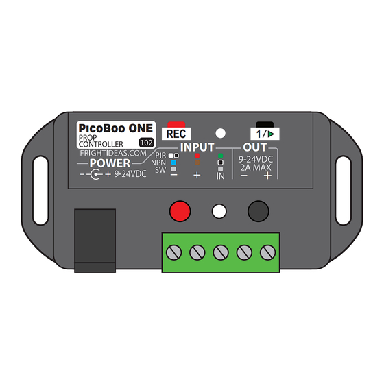
PICOBOO ONE
REC
1
INPUT
OUT
POWER
-
-
+
-
+
+
SOLID-STATE
OUTPUT
POWER / TRIGGER
TERMINAL BLOCK
POWER CAN BE SUPPLIED USING
THE BARREL CONNECTOR OR THE
TRIGGER TERMINAL BLOCK.
Connections and Controls
Record Button
Tap this button to start recording animation. Tap it again to stop.
Status LED
This multi-color LED indicates the current status of the PicoBoo ONE. See Operation.
Output / Play Button
During recording, this button is used to activate the output. Otherwise it will start playback.
Power Input 2.1mm
Your 12 or 24 volt DC power supply should plug in here. The connector is a center-positive
2.1mm barrel connector.
Power Input / Trigger
Connect your trigger here. Connecting – to IN will trigger the unit. The – and + pins on this
Terminal Block
block are connected directly to the – and + on the barrel connector. Feel free to supply or
borrow power here if it's more convenient.
Solid-State Output
This terminal block outputs 12 or 24 volts when the output is activated. The voltage output
Terminal Block
is equal to the voltage used to power the unit.
Identifying Your PicoBoo ONE Version
Version 1 has square red and green buttons. Version 2
has round red and black buttons and started shipping
late 2024. Version 2 has a few more features. See the
table to the right for the differences.
P���B�� ONE
REC
1
INPUT
OUT
POWER
-
-
+
-
+
+
Specifications
Power:
• 12 to 24VDC at 5-10mA
Input:
• Connect IN to -/GND to trigger
• Draws 6mA at 12V, 12mA at 24V
Output:
• Voltage Out equals Voltage In
• Maximum 2A
Animation:
• 4 minutes at 30 FPS
Sizing your Power Supply
Your PicoBoo ONE's power supply must be 12
or 24 volts DC. The voltage of the device you
want to control must match this voltage. The
wattage rating of the power supply must be
higher than the wattage required by the device
connected to the output.
Version 1
Version 2
SQUARE BUTTONS
ROUND BUTTONS
1 min of Animation
4 min of Animation
N.C. Input Option
No Looping Option
Blue Output LED
Advertisement

Subscribe to Our Youtube Channel
Related Manuals for Fright Ideas PicoBoo ONE v2


Summary of Contents for Fright Ideas PicoBoo ONE v2
- Page 1 Factory Reset Power up holding the 1/Play button for 10 seconds Power up holding BOTH buttons for a few seconds to PicoBoo ONE v2 until the LED turns yellow. Let go of 1/Play, the reset to factory defaults. current state is indicated on the LED as shown in the table below.
- Page 2 Startup INPUT At startup the PicoBoo ONE will indicate its current settings on the POWER ON Status LED (see Settings on the last page for details). If a PIR is INPUT detected a trigger delay will be activated to allow it to stabilize. STARTUP Operation SEQUENCE...
Need help?
Do you have a question about the PicoBoo ONE v2 and is the answer not in the manual?
Questions and answers