Table of Contents
Advertisement
Quick Links
AVIATION RECORDERS
COMPONENT MAINTENANCE MANUAL
FA2100CVR
MODEL FA2100 CVR
COCKPIT VOICE RECORDER
RECORDER PART NUMBERS:
2100−1010−( )
2100−1020−( )
2100−1025−( )
2100−1026−( )
2100−1027−( )
NOTE:
For FA2100CVR P/N:
2100−1020−90/−91/−93
Contact L−3AR Product Support
COMPONENT MAINTENANCE MANUAL
WITH
ILLUSTRATED PARTS LIST
P/N: 165E1689−00
IN ACCORDANCE WITH
FAA TSO−C123a
FAA TSO−C123b
EUROCAE ED−56A
EUROCAE ED−112
ARINC CHARACTERISTIC NO. 557
ARINC CHARACTERISTIC NO. 757, 757A
VENDOR CODE: 06141
23−70−04
Rev. 13
Dec. 09/13
Advertisement
Chapters
Table of Contents
Troubleshooting

Related Manuals for L3 Communications FA2100


Summary of Contents for L3 Communications FA2100
- Page 1 AVIATION RECORDERS COMPONENT MAINTENANCE MANUAL FA2100CVR MODEL FA2100 CVR COCKPIT VOICE RECORDER RECORDER PART NUMBERS: 2100−1010−( ) 2100−1020−( ) 2100−1025−( ) 2100−1026−( ) 2100−1027−( ) NOTE: For FA2100CVR P/N: 2100−1020−90/−91/−93 Contact L−3AR Product Support COMPONENT MAINTENANCE MANUAL WITH ILLUSTRATED PARTS LIST P/N: 165E1689−00...
- Page 2 AVIATION RECORDERS COMPONENT MAINTENANCE MANUAL FA2100CVR Model FA2100 CVR Rev. 13 Dec. 09/13 EXPORT CONTROL STATEMENT SSCVR/SSFDR TECHNOLOGY / DATA: “This Solid State Fight Data/Cockpit Voice Recorder Techni- cal Data is being exported from the United States in accor- dance with the Export Administration Regulations (ECCN #7E994), No License Required (NLR).
-
Page 3: Before Applying Power
AVIATION RECORDERS COMPONENT MAINTENANCE MANUAL FA2100CVR GENERAL This product and related documentation must be reviewed for familiarization with safety markings and instructions before operation. This instrument was constructed in an ESD (electro–static discharge) protected environ- ment. This is because most of the semiconductor devices used in this instrument are susceptible to damage by static discharge. - Page 4 AVIATION RECORDERS COMPONENT MAINTENANCE MANUAL FA2100CVR THIS PAGE IS INTENTIONALLY LEFT BLANK 23–70–04 Title Page iv Page iv Nov. 01/98 Nov. 01/98...
- Page 5 AVIATION RECORDERS COMPONENT MAINTENANCE MANUAL FA2100CVR RECORD OF HIGHLIGHTS Issue Revision Date of Comments Change Revision Dec. 09/13 Assembly, Dissassembly, and IPL updated to re- flect MOD DOT 13. ROSE/ROC/ADLP version numbers updated. Software checksums updated. Model configuration tables added for clarity. Au- tomatic Test Section revised Revision Jul.
- Page 6 AVIATION RECORDERS COMPONENT MAINTENANCE MANUAL FA2100CVR RECORD OF HIGHLIGHTS (Continued) Issue Revision Date of Comments Change Added new Section 200, Automatic Testing for Revision May 01/07 operational testing of CVR to include the ROC6 /w CATS software. Revised Disassembly & As- sembly sections to include p/n’s: 2100−1025−12 &...
- Page 7 Feb. 01/00 Includes changes to the IPL Section 1000 to in- corporate a new Audio Compressor PWA for FSK capability. Added the FA2100 GACVRs to the manual. Incorporated the Acquisition Proc- essor, p/n: 205E1931−00, turbo PWA changes along with the Revision 01 Software changes.
- Page 8 AVIATION RECORDERS COMPONENT MAINTENANCE MANUAL FA2100CVR THIS PAGE IS INTENTIONALLY LEFT BLANK 23–70–04 Highlights Rev. 01 Page viii Feb. 01/00...
- Page 9 AVIATION RECORDERS COMPONENT MAINTENANCE MANUAL FA2100CVR HIGHLIGHTS REVISION 13 DATED December 9, 2013 Pages which have been added or revised are outlined below, together with the highlights of Revision 13, dated December 9, 2013. Section Page Description Front Matter LOEP & TOC Changed the List of Effective Pages to reflect Revision 13 changes.
- Page 10 AVIATION RECORDERS COMPONENT MAINTENANCE MANUAL FA2100CVR HIGHLIGHTS REVISION 12 DATED July 3, 2013 Pages which have been added or revised are outlined below, together with the highlights of Revision 12, dated July 3, 2013. Section Page Description Front Matter LOEP & Changed the List of Effective Pages to reflect Revision 12 changes.
- Page 11 NAND memory to part number matrix. Adds description of PI/2. Added Section 13−16, 21, description of acquisition processor 205E2502−34. Removed descrip- 22, 23, 25, tion of FA2100 CVR p/n: S2100−1020−91 29, 30−34, 35, 36, 43, 48−56, 64, Testing & Fault...
- Page 12 AVIATION RECORDERS COMPONENT MAINTENANCE MANUAL FA2100CVR HIGHLIGHTS REVISION 10 DATED Jun. 15, 2012 Pages which have been added or revised are outlined below, together with the highlights of Revision 10, dated Jun. 15, 2012. Section Page Description List of FSB’s Front Matter xix −...
- Page 13 AVIATION RECORDERS COMPONENT MAINTENANCE MANUAL FA2100CVR HIGHLIGHTS REVISION 09 DATED Apr. 30, 2010 Pages which have been added or revised are outlined below, together with the highlights of Revision 09, dated Apr. 30, 2010. Section Page Description Title i − ii Updated for Revision 9.
- Page 14 AVIATION RECORDERS COMPONENT MAINTENANCE MANUAL FA2100CVR HIGHLIGHTS REVISION 08 DATED Jul. 30, 2009 Pages which have been added or revised are outlined below, together with the highlights of Revision 08, dated Jul. 30, 2009 Section Page Description Title i − ii Updated for Revision 8.
- Page 15 AVIATION RECORDERS COMPONENT MAINTENANCE MANUAL FA2100CVR HIGHLIGHTS REVISION 07 DATED DECEMBER 01, 2008 Pages which have been added or revised are outlined below, together with the highlights of Revision 07, dated December 01, 2008 Section Page Description Title i − ii Updated for Revision.
- Page 16 Test Station (CATS) software. Disassembly 302−309 Updated procedures and drawings to include new Audio Compressor board and Crash Survivable Memory Unit (CSMU) for the FA2100 CVR. Changed 2100−1025−02 to 2100−1025−( ) or− XX. Revised beacon battery replacement date. Cleaning 402, 403 Updated Figure 401 to include new CSMU p/n callouts.
- Page 17 101, 105, 112 Updated test section/procedure to include p/n: 2100−1025−02, Isolation 114−118, 122, 2−hour HQ only recorder. Updated FA2100 CVR test bench setup re- 124−127, quirements and Table 1. Recommeded Standard Test Equipment. 141−142 Added Data Link Check to Table 102. Operational Test Procedure.
- Page 18 AVIATION RECORDERS COMPONENT MAINTENANCE MANUAL FA2100CVR HIGHLIGHTS REVISION 04 DATED JAN. 01, 2003 Pages which have been added or revised are outlined below, together with the highlights of Revision 04, dated Feb. 01/2003. Section Page Description Title 1 − 2 Updated for Revision.
- Page 19 AVIATION RECORDERS COMPONENT MAINTENANCE MANUAL FA2100CVR HIGHLIGHTS REVISION 03 DATED MAR. 01, 2001 Pages which have been added or revised are outlined below, together with the highlights of Revision 03, dated Mar. 01/2001. Section Page Description Title 1−2 Updated for Revision. Front Matter LOEP &...
- Page 20 Compressor PWA. Updated numerical index and part number list to Diagrams reflect shift in item numbers for all FA2100 CVR models. Updated nu- merical index to include ULDs. Updated item numbers for Audio Com- pressor PWA and ULDs. Updated include correct RTCA / DO−178B level.
- Page 21 Processor replacement. Updated Portable Interface figure and menu 912−916 structures. Illustrated Parts 1004−1014 Update the Configuration Matrix. Updated the Numerical Index. Add- List ed the new Audio Compressor PWA for FSK capability. Added the FA2100 GACVRs to the IPL. 23–70–04 Highlights Rev. 01 Page xxi Feb. 01/00...
- Page 22 AVIATION RECORDERS COMPONENT MAINTENANCE MANUAL FA2100CVR THIS PAGE IS INTENTIONALLY LEFT BLANK 23–70–04 Highlights Rev. 13 Page xxii Dec. 09/13...
-
Page 23: Record Of Revisions
AVIATION RECORDERS COMPONENT MAINTENANCE MANUAL FA2100CVR RECORD OF REVISIONS REV. INSERTION REV. INSERTION REV. INSERTION DATE DATE DATE Dec. 09/13 Jul. 03/13 May 21/13 Jun. 15/12 Apr. 30/10 Jul. 30/09 Dec. 01/08 May 01/07 Oct. 01/04 Jan. 01/03 Mar. 01/01 Jun. - Page 24 AVIATION RECORDERS COMPONENT MAINTENANCE MANUAL FA2100CVR THIS PAGE IS INTENTIONALLY LEFT BLANK 23–70–04 Record of Revisions Page xxiv Nov. 01/98...
-
Page 25: Service Bulletin List
COMPONENT MAINTENANCE MANUAL FA2100CVR SERVICE BULLETIN LIST SERVICE BULLETIN DATE EFFECTIVITY DESCRIPTION FA2100 CVR Sep. 08/98 P/N: 2100-1010-00 Modification of Aircraft Interface PWA, FSB001 P/N: 2100-1020-00 p/n: 205E1593-00 to prevent erroneous 23−70−04−01 test tone activation due excessive noise environment. MOD-DOT #1 FA2100 CVR Apr. - Page 26 AVIATION RECORDERS COMPONENT MAINTENANCE MANUAL FA2100CVR SERVICE BULLETIN LIST FA2100 CVR Dec. 15/05 P/N: 2100-1020-( ) This modification includes replacing the exist- ing Audio Compressor PWA, p/n: FSB009 P/N: 2100-1020-( ) 205E1596−00, 205E1849−00, 205E1849−10, 23−70−04−09 205E1849−02, 205E1849−03, 205E1849−13, 205E1849−04 or 205E1849−14 with a re- placement Audio Compressor PWA, p/n: 205E3977−10, 205E3977−12, 205E3977−13...
- Page 27 AVIATION RECORDERS COMPONENT MAINTENANCE MANUAL FA2100CVR SERVICE BULLETIN LIST FA2100 CVR Nov. 09/10 P/N: 2100−1010−( ) Introduction of Improved Storage Capacitor MOD−DOT #13 FSB017 P/N: 2100−102X−( ) 23−70−04−17 FA2100 CVR Jan. 14/11 P/N: 2100−1010−00 Replacement of Non−Conforming Hardware MOD−DOT N/A FSB018 P/N: 2100−1010−51...
- Page 28 AVIATION RECORDERS COMPONENT MAINTENANCE MANUAL FA2100CVR THIS PAGE IS INTENTIONALLY LEFT BLANK 23–70–04 Service Bulletin Page xxviii Nov. 01/98...
- Page 29 AVIATION RECORDERS COMPONENT MAINTENANCE MANUAL FA2100CVR LIST OF EFFECTIVE PAGES Section Page Date Section Page Date Title Page Rev. 13 xxxiv Dec. 09/13 Table of Contents Rev. 13 Dec. 09/13 Rev. 13 Dec. 09/13 Rev. 13 xxxv Dec. 09/13 Nov. 01/98 Rev.
-
Page 30: List Of Effective Pages
AVIATION RECORDERS COMPONENT MAINTENANCE MANUAL FA2100CVR LIST OF EFFECTIVE PAGES (Continued) Section Page Date Section Page Date Description and Operation Rev. 06 May 01/07 Rev. 11 May 21/13 (Continued) Rev. 11 May 21/13 Rev. 11 May 21/13 Rev. 11 May 21/13 Rev. - Page 31 AVIATION RECORDERS COMPONENT MAINTENANCE MANUAL FA2100CVR LIST OF EFFECTIVE PAGES (Continued) Section Page Date Section Page Date Testing and Troubleshooting Rev. 13 Dec. 09/13 Rev. 13 Dec. 09/13 (Continued) Rev. 13 Dec. 09/13 Rev. 07 Dec. 01/08 Rev. 13 Dec. 09/13 Rev.
- Page 32 AVIATION RECORDERS COMPONENT MAINTENANCE MANUAL FA2100CVR LIST OF EFFECTIVE PAGES (Continued) Section Page Date Section Page Date Automatic Testing Rev. 13 Dec. 09/13 Rev. 13 Dec. 09/13 (Continued) Rev. 13 Dec. 09/13 Rev. 13 Dec. 09/13 Rev. 13 Dec. 09/13 Rev.
- Page 33 AVIATION RECORDERS COMPONENT MAINTENANCE MANUAL FA2100CVR LIST OF EFFECTIVE PAGES (Continued) Section Page Date Section Page Date Assembly Rev. 13 Dec. 09/13 Rev. 04 Jan. 01/03 Rev. 13 Dec. 09/13 Rev. 04 Jan. 01/03 Rev. 06 May 01/07 Nov. 01/98 Rev.
- Page 34 AVIATION RECORDERS COMPONENT MAINTENANCE MANUAL FA2100CVR LIST OF EFFECTIVE PAGES (Continued) Section Page Date Section Page Date Illustrated Parts List Rev. 13 1017 Dec. 09/13 Rev. 13 1018 Dec. 09/13 (Continued) Rev. 11 1019 May 21/13 Rev. 13 1011 Dec. 09/13 Rev.
-
Page 35: Table Of Contents
..............FA2100 CONFIGURATIONS . - Page 36 ........... . MODEL FA2100 CVR SYSTEM THEORY OF OPERATION .
- Page 37 AVIATION RECORDERS COMPONENT MAINTENANCE MANUAL FA2100CVR TABLE OF CONTENTS (Continued) SUBJECT/DESCRIPTION Page Audio Compressor ..........Crash Survivable Memory Unit .
- Page 38 Installing Software Upload Utility and CICC Interface Programs ....To upload the FA2100 Software perform the following steps: ....
- Page 39 AVIATION RECORDERS COMPONENT MAINTENANCE MANUAL FA2100CVR TABLE OF CONTENTS (Continued) SUBJECT/DESCRIPTION Page Bulk Erase ............Test Tone .
- Page 40 AVIATION RECORDERS COMPONENT MAINTENANCE MANUAL FA2100CVR TABLE OF CONTENTS (Continued) SUBJECT/DESCRIPTION Page (14) Signal To No Signal ..........(15) Shutdown .
- Page 41 AVIATION RECORDERS COMPONENT MAINTENANCE MANUAL FA2100CVR TABLE OF CONTENTS (Continued) SUBJECT/DESCRIPTION Page CHECK GENERAL ..............CHECKS .
- Page 42 ........FA2100 Software Upload Cable Assembly & Distribution Diskettes .
-
Page 43: List Of Figures
104. Acquisition Processor PWA (AP) Test Point Locations(P/N: 205E1591−00) ..105. Typical Software Upload Setup For FA2100 Recorder with CICC/2 Cable ..201. ROC/6 w/CVR Automated Test Station Software (CATS) FA2100CVR TEST SETUP . - Page 44 AVIATION RECORDERS COMPONENT MAINTENANCE MANUAL FA2100CVR LIST OF FIGURES (Continued) FIGURE TITLE PAGE 208. CVR Test, Instruction Message ..........209.
- Page 45 AVIATION RECORDERS COMPONENT MAINTENANCE MANUAL FA2100CVR LIST OF FIGURES (Continued) FIGURE TITLE PAGE 240. Volume Mixer, Speaker Levels ..........241.
- Page 46 AVIATION RECORDERS COMPONENT MAINTENANCE MANUAL FA2100CVR LIST OF FIGURES (Continued) FIGURE TITLE PAGE 272. CATS, CVDR Fault History Log ..........273.
- Page 47 ......801. Outline & Dimension Drawing Model FA2100 CVR Recorder P/N: 2100-1010-( ) & 2100-102X-( ) ..
- Page 48 921. FA2100CVR Download Cable, p/n 17TES0078, Wiring Diagram ....1. Model FA2100 Cockpit Voice Recorder PN: 2100-1010-( ) & 2100-102X-( ) ..
- Page 49 ..........105. FA2100 CVR Fault Code Corrective Actions .
- Page 50 AVIATION RECORDERS COMPONENT MAINTENANCE MANUAL FA2100CVR THIS PAGE IS INTENTIONALLY LEFT BLANK 23–70–04 Table of Contents Rev. 13 Page l Dec. 09/13...
-
Page 51: Introduction
INTRODUCTION 1. GENERAL This Component Maintenance Manual (CMM) documents the operation of and suggested maintenance for the Model FA2100 Cockpit Voice Recorder, herein after referred to as the FA2100CVR. The FA2100CVR meets the performance requirements of ED-56A, while complying with the interface requirements of ARINC 557/757 cockpit voice input data including Rotor Speed and GMT interfaces. -
Page 52: Document Requirements
AVIATION RECORDERS COMPONENT MAINTENANCE MANUAL FA2100CVR Line Replaceable Unit MTBF Mean Time Between Failures Onboard Maintenance System Personal Computer PCMCIA Personal Computer Memory Card International Association (now known as PC Card) Portable Interface printed wiring assembly power REC LVL Record Level Recorder Interface Unit Read−Out Center ROSE... -
Page 53: Maintenance Philosophy
DESCRIPTION AND OPERATION This section contains the description and operation information for the Model FA2100 Cockpit Voice Recorder. Line art is used to illustrate the unit, its intercon- nections and functionality. This section also contains the Model FA2100CVR Theory of Operation. -
Page 54: Testing And Troubleshooting
Fault isolation is provided to a Level-2 maintenance, or circuit board removal and replacement level. No calibration of circuit boards within the Model FA2100CVR is required. The Model FA2100 Solid-State Cockpit Voice Recorder is considered an “ON CONDITION LRU”. DISASSEMBLY... -
Page 55: Assembly
ASSEMBLY This section contains detailed step-by-step procedures describing the complete as- sembly of the Model FA2100 Solid-State Cockpit Voice Recorder. Each major as- sembly procedure is accompanied with a line art exploded-view of the subassembly area which is cross referenced to the applicable Illustrated Parts List (IPL) drawing for ordering replacement parts. -
Page 56: Component Maintenance Manual (Cmm) Effectivity
AVIATION RECORDERS COMPONENT MAINTENANCE MANUAL FA2100CVR Table 1. Shop Verification Procedure Chapter Date of Verification Testing & Fault Isolation Mar. 25/13 Automatic Testing Mar. 25/13 Disassembly Mar. 18/13 Assembly Mar. 18/13 Note: Contact L-3 Aviation Recorders, to verify this date sensitive information when using this manual to develop other documentation. -
Page 57: Description And Operation
ED-56A or ED−112 and to accept requirements of ARINC 557/757A Characteristics including Ro- tor Speed Encoder (RSE) and Greenwich Mean Time (GMT) interface. The FA2100 CVR recorder is designed as a maintenance free recorder. There is no periodic or scheduled maintenance required for this recorder. -
Page 58: System Description
Control. 3. SYSTEM DESCRIPTION Refer to Figure 3. The Model FA2100 Cockpit Voice Recorder System consists of the re- corder and an externally mounted control unit or externally mounted preamplifier with re- mote microphone. Interconnection between the recorder and the control unit is accom- plished using aircraft wiring. -
Page 59: Underwater Acoustic Beacon
AVIATION RECORDERS COMPONENT MAINTENANCE MANUAL FA2100CVR The Model FA2100CVR consists of an Underwater Locating Device, chassis and front panel, four internal level-2 replaceable assemblies: the Aircraft Interface PWA, Audio Compressor PWA, Acquisition Processor PWA, and the Crash Survivable Memory Unit (CSMU) which contains the solid-state flash memory used as the recording medium. - Page 60 ASSEMBLY 2100‐1025‐XX, ‐1026‐XX, and ‐1027‐XX only. RIPS Status Monitoring. 2100-1025-22 & (CRASH PROTECTED SOLID STATE MEMORY) 2100-1026-XX only. Figure 3. Model FA2100 CVR, (2100‐1010‐00, 2100‐1020‐00/02/90, 2100‐1025‐XX, 2100‐1026‐XX and 2100‐1027‐XX) Functional System Block Diagram 23–70–04 Description and Operation Page 4 Rev. 13 Page 4 Dec.
- Page 61 ASSEMBLY All GACVR's only use the Model S056 Remote Mic. (CRASH PROTECTED SOLID STATE MEMORY) Figure 4. Model FA2100 GACVR (2100‐1010‐50/‐51 and 2100‐1020‐50/‐51) Functional System Block Diagram 23–70–04 Description and Operation Page 5 Rev. 04 Page 5 Jan.
-
Page 62: Stop Recording Command
Control Unit Operating Power and Monitor Audio Signals The FA2100 CVR provides the control unit with +18 Vdc operating power, monitor audio to the headset jack, and a TEST indicator signal. Refer to Figure 5, an Audio Output channel for test monitoring provides a combina- tion of four High Quality (for 30-minute recorders) or two Standard Quality (for 120-minute recorders and 2100−1020−XX pre MOD−DOT #7) or four High Quality... - Page 63 CAM – Cockpit Area Microphone CH – Channel HQ – High Quality SQ – Standard Quality Figure 5. (Sheet 1 of 2) Model FA2100 CVR, 30‐Minute and 120‐Minute Audio Monitor Schemes 23–70–04 Description and Operation Page 7 Rev. 06 Page 7 May 01/07 Nov.
-
Page 64: Control Unit Test And Bulk Erase Signals
ATA 23–70–05, Part Number 165E1747-00. The +18 Vdc is a short-circuit protected 30 mA line. All control units provide the FA2100 CVR with three control signals: Erase “A”, Erase “C”, and Push-To-Test. The Erase “A” and Erase “C” signals are used to initiate a bulk erasure of the crash protected solid-state memory. -
Page 65: Voice Data Interface Characteristics
Refer to Paragraph 5 for detailed pin-outs of the rear interface connector. In the −02 FSK version of the FA2100 CVR, CH 1 or CH 3 may have an FSK GMT input applied along with the standard audio signal. -
Page 66: Data Recording Storage
AVIATION RECORDERS COMPONENT MAINTENANCE MANUAL FA2100CVR Data Recording Storage Refer to Figure 6 for a diagram of the FA2100CVR recording schemes used in the 30-minute and 120-minute recorders and Table 1 for a breakdown of the recording durations for each of the High Quality and Standard Quality combined channels. The audio received from the cockpit area microphone (CAM) is applied to the CAM input channel (CH4). - Page 67 CAM – Cockpit Area Microphone CH – Channel HQ – High Quality SQ – Standard Quality Figure 6. (Sheet 1 of 2) Model FA2100 CVR, 30-Minute and 120-Minute Recording Schemes 23–70–04 Description and Operation Page 11 Rev. 06 Page 11 May 01/07 Nov.
-
Page 68: Output Audio Quality
OMS − On board Maintenance System* * P/N 2100−1025/1026−XX only Figure 6. (Sheet 2 of 2) Model FA2100 CVR, 30-Minute and 120-Minute Recording Schemes Output Audio Quality The FA2100CVR’s audio quality meets or exceeds the audio quality specified in Chapter 3 of ED–56A and Part I of ED−112. Specifically, the Reference Signal is 1-kHz at 3 Vrms for the voice channels, and 1-kHz at 2 Vrms for the CAM channel. -
Page 69: Gmt/Fsk Output Signals
Audio data. In the case of the 30-minute Model FA2100 CVR, p/n: 2100–1010–( ), 30 minutes of GMT/RSE data is stored. In the case of the 120-minute Model FA2100 CVR, p/n: 2100–102X–( ), a full 120 min- utes of GMT/RSE data is stored. -
Page 70: On Board Maintenance System (Oms)
OMS computer four times per second. When the recorder is in Interactive mode, the OMS computer can request the status of the recorder through a series of menus. The OMS feature can be found on the FA2100 CVR p/n: 2100−1025/1026/1027−( ) only. -
Page 71: Data Link
Data Link system will continue to send Aloha mes- sages until the recorder’s status changes. The Data Link feature can be found on the FA2100 CVR p/n: 2100−1025/1026/1027−( ) only. For p/n 2100−1025/1026/1027−XX CVRs, the Audio and Data Link Playback (ADPL) soft- ware may be used to download and analyze the audio data. -
Page 72: Storage Capacity
G. Storage Capacity The Model FA2100CVR storage media is designated as the Crash Survivable Me- mory Unit (CSMU). The CSMU in the Model FA2100, p/n 2100–1010–( ), contains flash memory with enough storage capacity to allow continuous recording of the four high quality audio channels for a minimum of 30 minutes. -
Page 73: Data Reproduction
AVIATION RECORDERS COMPONENT MAINTENANCE MANUAL FA2100CVR Additionally, the audio data can be down-loaded through the GSE connector, stored on Type III PCMICA portable hard disks inserted in the PI Unit for later playback. The Portable Interface Unit must have MOD-DOT 1 and the FA2100CVR must have MOD-DOT 2 for Audio data downloading capability to be activated. -
Page 74: Crash Survivable Memory Unit
Crash Survivable Memory Unit The Crash Survivable Memory Unit (CSMU) is the environmentally hardened memory storage assembly of the Model FA2100. Electrical interface to the CSMU is made by the Acquisition Processor PWA via a single 16-contact connector at con- nector J1. - Page 75 AVIATION RECORDERS COMPONENT MAINTENANCE MANUAL FA2100CVR A Control Unit or Preamplifier is a required component of a CVR installation and functions as the FA2100CVR cockpit user interface; however, this is not required for GACVR recorders. Control Units contain a preamplifier for interfacing the cockpit area microphone with the CVR, and provide a means for activating the test function, by pressing a green TEST push button and observing an green TEST indicator.
-
Page 76: Remote Microphone Module
If the SMP is operating properly it performs the task of monitoring the above listed faults in the other FA2100 processors. It detects errors in the Flight Data Processor (FDP) and Audio Compressor Processor (ACP) by checking for protocol errors and unexpected data values. -
Page 77: Fa2100 Cvr Specifications
CSMU can be re- trieved. In summary each processor, RAM and programmable memory device in the FA2100 is monitored by BIT. They are checked at power−up and continuously monitored during operation of the recorder. -
Page 78: Physical Characteristics
AVIATION RECORDERS COMPONENT MAINTENANCE MANUAL FA2100CVR ARINC Report 604–1 Guidance for Design and Use of Built-In-Test-Equipment ARINC Report 624 Design Guidance for On-board Maintenance System ARINC Characteristic 557 Cockpit Voice Recorder ARINC Characteristic 757 Cockpit Voice Recorder (10) ARINC Characteristic 757A Cockpit Voice Recorder (11) ARINC Characteristic 777−1 Recorder Independent Power Supply (RIPS) -
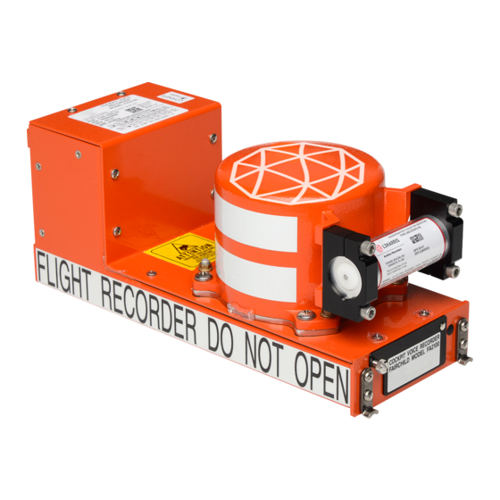
Page 79: Installation
Instruction Manual, p/n: 165E1846-00. The Model FA2100CVR is an environmentally hardened unit housed in an ARINC 404A 1/2-ATR short box painted international orange. The FA2100 does not require external shock mounting for installation into the aircraft. However, the Model FA2100CVR requires mounting in an approved mount system for installation into the aircraft. - Page 80 OPEN = IN FLIGHT CLOSED = WEIGHT ON WHEELS For GACVR versions refer to Figure 9. Wiring for all CVR's except for 2100-1025-XX and 2100-1026-XX, are compliant to ARINC 757-3. Figure 8. Interwiring Diagram, Recorder FA2100 CVR (2100-1010-00, 2100-1020-00/-02, & 2100-1025/1026-XX) 23–70–04 Description and Operation Page 24 Rev.
- Page 81 AVIATION RECORDERS COMPONENT MAINTENANCE MANUAL FA2100CVR Notes for Figure 8: Recommended minimum wire size is #22: #24 is electrically permissible except for power leads, where #18 wire is desirable on long-runs (pins 2, 3, 9, & 17) Wire resistance should not exceed 1 ohm for power leads and should not exceed 5 ohms for signal leads. All wiring should be MIL–W–22759 or MIL–C–27500.
- Page 82 DATA LINK VALID MIC HIGH (BLACK) VOICE ERASE ”C” MIC LOW (SHEILD)) BRAKE GEAR BULK ERASE INTERLOCK (TYPICAL) Figure 9. ARINC 757A Interwiring Diagram, Recorder FA2100 CVR (2100-1027-XX) 23–70–04 Description and Operation Page 26 Rev. 11 Page 26 May 21/13...
- Page 83 AVIATION RECORDERS COMPONENT MAINTENANCE MANUAL FA2100CVR Notes for Figure 9: Recommended minimum wire size is #22; however, wire size #24 is electrically permiss- ible except for long−run power leads where #18 wire is recommended (pins 3, 9, & 17). Wire resistance should not exceed 1 ohm for DC power leads and should not exceed 5 ohms for other leads.
- Page 84 Refer to Notes on the Following Page. BULK ERASE INTERLOCK (TYPICAL) OPEN = IN FLIGHT CLOSED = WEIGHT ON WHEELS Figure 10. Interwiring Diagram, Recorder FA2100 GACVR (2100-10X0-50/-51) with Customer−Furnished Control Panel 23–70–04 Description and Operation Page 28 Rev. 03 Page 28 Mar.
- Page 85 AVIATION RECORDERS COMPONENT MAINTENANCE MANUAL FA2100CVR Notes for Figure 10 Recommended minimum wire size is #22; however, wire size #24 is electrically per- missible except for long-run power leads where #18 wire is recommended (pins 9 & Wire resistance should not exceed 1 ohm for power leads and should not ex- ceed 5 ohms for signal leads.
-
Page 86: Theory Of Operation
PWAs. The software level theory describes the modes of operation of the recorder software. MODEL FA2100 CVR SYSTEM THEORY OF OPERATION The ARINC 557/757/757A, Model FA2100CVR consists of four subassemblies, the Aircraft Interface Printed Wiring Assembly (PWA), the Audio Compressor PWA, the Acquisition Processor PWA, and Crash Survivable Memory Unit (CSMU). -
Page 87: Aircraft Interface (Ai) Pwa
AVIATION RECORDERS COMPONENT MAINTENANCE MANUAL FA2100CVR Aircraft Interface (AI) PWA The Aircraft Interface (AI) PWA mounts within the rear of the Cockpit Voice Recorder chassis and provides the interface between the aircraft and the Cockpit Voice Re- corder’s Audio Compressor (AC) and Acquisition Processor (AP) functions. The Air- craft Interface PWA also includes the storage power supply and provides RF filtering and lightning protection for all input and output signals that interface with the aircraft. -
Page 88: Arinc 557/757/757A Aircraft Interface Signals To Aircraft Interface Pwa
AVIATION RECORDERS COMPONENT MAINTENANCE MANUAL FA2100CVR The ARINC 557/757 Aircraft Interface provides output signal conditioning for: CVR Fault Audio Out for Monitoring at the Control Unit headset. Data Link and OMS (Only for P/N: 205E2503−01 and 205E1763−08) The Aircraft Interface also includes the storage supply portion of the power supply. This supply conditions the applied ac or dc input power and charges the 39 Vdc stor- age capacitor to provide the energy required to operate the Cockpit Voice Recorder during power outages up to 200 milliseconds in duration. -
Page 89: Arinc 557/757/757A Aircraft Interface Signals Between Aircraft Interface And Audio Compressor Pwas
* Only used in 2100−1025/1026−/1027( ) Models of CVR. ARINC 557/757/757A Aircraft Interface Signals Between Aircraft Interface and Audio Compressor PWAs Table 4 lists the signal interfaces between the FA2100 Aircraft Interface PWA and Audio Compressor PWA. Table 4. Aircraft Interface PWA to Audio Compressor PWA Interface Signals... -
Page 90: Arinc 557/757A Aircraft Interface Signals
+5V from 10 kohms and indicates no fault. When preamp power is less than +15 V output goes low and sinks 3.5 ma at less than 0.4 V. ARINC 557/757A Aircraft Interface Signals Table 5 lists the signal interfaces between the FA2100 Aircraft Interface PWA and Acquisition Processor PWA. 23–70–04... -
Page 91: Audio Compressor (Ac) Pwa
AVIATION RECORDERS COMPONENT MAINTENANCE MANUAL FA2100CVR Table 5. Aircraft Interface PWA to Acquisition Processor PWA Interface Signals Signal Name Description 39VDC 36.6 $2 volt dc output provides up to 16 watts, maximum, to the main power supply. Up to an additional 4 watts can be supplied to external test equipment with nominal input voltages and room tem- perature. -
Page 92: Audio Compressor (Ac) Pwa Current Configuration Where Used
AVIATION RECORDERS COMPONENT MAINTENANCE MANUAL FA2100CVR The Audio Compressor PWA receives conditioned audio, GMT, rotor speed, and discrete command/control data from the AI concurrently. Audio and ARINC 429 in- put data are processed by the AC and formatted into 16–bit wide words for serial Time Division Multiplexed (TDM) Bus transmission to the AP. -
Page 93: Audio Interface
AVIATION RECORDERS COMPONENT MAINTENANCE MANUAL FA2100CVR Audio Interface The Audio Interface consists of four audio input channels. Input Channels 1–3 correspond to one of three crew member voice inputs. The ED–56A and ED−112 reference voltage input to the AC for Channels 1–3 is 2.0 Vrms into a 10 kohm load and a specified bandwidth of 150–3500 Hz. -
Page 94: Audio Compressor/Acquisition Processor Interface
The Acquisition Processor PWA actually consists of two separate processors: the Store Manager Processor (SMP) and the Flight Data Processor (FDP). However, in the FA2100 CVR configuration the SMP is the only processor functioning, with the exception of p/n: 205E2502−14 since the Data Link signals utilize the FDP proces- sor. -
Page 95: Aircraft Interface
AVIATION RECORDERS COMPONENT MAINTENANCE MANUAL FA2100CVR The Acquisition Processor interfaces with three internal functional modules: Aircraft Interface, Audio Compressor, and CSMU. Additionally, is an external interface to the Ground Support Equipment (GSE). Aircraft Interface The Aircraft Interface (AI) Interface involves the following external power inputs and outputs: External power input +39 Vdc storage supply, +15 V, and +5 V (storage) from the Aircraft Interface PWA. - Page 96 As defined in RTCA/DO–178B, the Criticality Category of the Model FA2100CVR is classi- fied as Minor. Accordingly, the software in the FA2100 CVR will comply with the Level D requirements of RTCA/DO–178B. Store Manager Processor Software Organization The SMP software is organized as a multi−tasking environment with individual mod-...
- Page 97 AVIATION RECORDERS COMPONENT MAINTENANCE MANUAL FA2100CVR the CVR operates in the record state for most of its power on time. Each of the states will be discussed in the following sections. Initialization State The SMP goes through the initialization sequence when reset is asserted as a result of power up or watchdog timeout.
- Page 98 AVIATION RECORDERS COMPONENT MAINTENANCE MANUAL FA2100CVR ized, recording will commence with the first digitized audio data received from the Audio Compressor board. The CVR Executive task enables the TDM re- ceive routine to begin collecting data form the Audio Compressor stream sent over the TDM bus.
- Page 99 72‐ms Superframe Sync Mark (1) 36‐Word Special Frame per 4 Superframes * Block headers & Block boundaries Not Shown Figure 12. 2–Hr FA2100 CVR (pre MOD−DOT #7) Word Partition Structure Streams 23–70–04 Description and Operation Page 43 Rev. 06 Page 43 May 01/07 Nov.
- Page 100 AVIATION RECORDERS COMPONENT MAINTENANCE MANUAL FA2100CVR The CVR Executive manages the storage of received channel specific au- dio data packets to the CSMU. The CVR Executive examines the packet, determines which memory partition should be addressed, and sends the complete packet to the Flash Manager for storage in the CSMU. The CVR Executive task also manages the erase look−ahead function to insure that there is always a new erased block of flash memory available for impend- ing memory write operations.
- Page 101 AVIATION RECORDERS COMPONENT MAINTENANCE MANUAL FA2100CVR The Audio Channelizer task receives the shutdown message, but contin- ues to process any 8 ms blocks of audio data that may be in its input queue. When it has processed all pending data, the Audio Channelizer zero fills any remaining partial 36 work channel specific packets.
-
Page 102: Data Structures
Data Structures The primary data structure utilized in the FA2100 CVR is the organization of the crash protected flash memory contained in the CSMU. The partitioning of the... - Page 103 NOTE: This representation does not SQV = Standard Quality Voice include p/n: 2100-1025-( ), which is a SQC = Standard Quality CAM 2-hour HQ only recorder. Figure 13. 2–Hr FA2100 CVR Memory Structure 23–70–04 Description and Operation Page 47 Nov. 01/98...
-
Page 104: Fault Processing
Kwords long. An erase block is the smallest physical block of a flash memory device that can be erased at one time. The FA2100 CVR software partitions each 32 Mb Erase Block into an eight word header followed by 910 logical packets of 36 words each. These packets are the fundamental units which are built and stored into the CSMU. -
Page 105: Fault Processing Event Types And Descriptions
AVIATION RECORDERS COMPONENT MAINTENANCE MANUAL FA2100CVR Any detected fault condition asserts the fault output from the CVR. Some faults are “latched’ meaning that the fault indication will continue to be asserted (regardless of power cycling) until it is cleared by maintenance action. Other faults may relent, al- lowing normal CVR operation to continue. -
Page 106: Memory Requirements
Software Partitioning Software for the Model FA2100 Solid State Flight Recorders will be partitioned into two parts. This is to accommodate the use of two DSPs. One DSP, called the Flight Data Processor (FDP), is responsible for the collection, processing, and forwarding of Data Link messages. - Page 107 AVIATION RECORDERS COMPONENT MAINTENANCE MANUAL FA2100CVR Channel Monitor/Test Select Output CVR Fault Output GMT Input Push−To−Test Input Record On Input Rotor Speed Input Stop Record Input Test Good Output The system level interfaces used by all configurations are: Power In Power Return GSE Input GSE Output...
-
Page 108: P/N 2100−1025/1026/1027−( ) Software Fault Warning Failures
AVIATION RECORDERS COMPONENT MAINTENANCE MANUAL FA2100CVR The fault signal is indicated for any of the following (as per ED112 §2−1.4.2): failure of the audio or digital interface and processing equipment. failure of the recording medium and/or drive mechanism. failure of the recorder to store the information in the storage medium as shown by checks fo the recorded material including, if reasonably practi- cable, correct correspondence with the inputs. - Page 109 AVIATION RECORDERS COMPONENT MAINTENANCE MANUAL FA2100CVR Push−to−Test (PTT) Functionality The Push−to−Test functionality (already implemented on existing aircraft and stan- dardized in ARINC 757A specification) is used to provide the flight crew with the abil- ity to quickly confirm good serviceability of the CVR before flight as required by the applicable regulation.
- Page 110 AVIATION RECORDERS COMPONENT MAINTENANCE MANUAL FA2100CVR G. Recorder Synchronization The FA2100CVR equipment is designed to be able to record time code from an ARINC 429 in priority and later FSK source (the frequencies used are 3607Hz +/− 30Hz and 4193Hz +/− 30Hz), depending on the source used on the aircraft. For Models FA2100CVR, p/n: 2100−1020−02/2100−1025−( ), 2100−1026−( ), and 2100−1027−( ) the recorder automatically detects which source is received, ac- quires the time data, and stores it into memory.
-
Page 111: Cvr Rips Pin Assignment For P/N: 2100−1025−22 & 2100−1026/1027−( )
AVIATION RECORDERS COMPONENT MAINTENANCE MANUAL FA2100CVR CVR RIPS status monitoring (P/N: 2100−1025−22, 2100−1026−( ), and 2100−1027−( ) only) The Recorder Independent Power Supply (RIPS) is an ON−CONDITION LRU de- signed to provide 10 minutes CVR backup power as per ARINC Characteristic 777−1. - Page 112 AVIATION RECORDERS COMPONENT MAINTENANCE MANUAL FA2100CVR RIPS Fault The CVR will use Pin 29 to receive the RIPS Failure Status Discrete output. This discrete input is presently assigned in ARINC 757A as FDR Rate A for combination recorder applications. This discrete input is not presently utilized by the pre RIPS CVR software.
-
Page 113: Cvr Oms Output Words
AVIATION RECORDERS COMPONENT MAINTENANCE MANUAL FA2100CVR If the RIPS is not present, then any reference to RIPS in the Interactive OMS output pages will be suppressed. However, in the case where the CVR is re- moved from an aircraft with RIPS and re−installed on an aircraft without RIPS, it is possible that previous flight leg RIPS fault information, stored in the CVR fault log while installed on the aircraft with RIPS, will be displayed. -
Page 114: Cvr Pins Assigned To Rips Status Monitoring
AVIATION RECORDERS COMPONENT MAINTENANCE MANUAL FA2100CVR As an additional capability, this CVR also monitors the status of an attached Record- er Independent Power Supply, if present, and includes that status with the OMS out- put reporting. The RIPS status is monitored using the CVR input pins listed in Table 1.2: Table 12. -
Page 115: Cvr Fault Reporting Interactions
AVIATION RECORDERS COMPONENT MAINTENANCE MANUAL FA2100CVR CVR Recording Failure (Record Enable) 0: OK 1 : Failure RIPS Maintenance Status (Battery) (pin 38) 0: No Maint. 1 : Maint. Req. RIPS Active Status (pin 10) 0: Not Active 1 : RIPS Active RIPS Presence Status (Pin 42) 0: Not Pres. -
Page 116: Cvr Status Word Fault Reporting Criteria
AVIATION RECORDERS COMPONENT MAINTENANCE MANUAL FA2100CVR Like any other internal CVR fault, this audio circuit failure will be reported using: the Label 350 output Bit 11, the CVR Fault Status discrete output, and the Push−to−Test results. If an audio input circuit failure occurs after a successful Push−to−Test oper- ation, it will not be detected, or reported, until the next Push−to−Test is initiated. - Page 117 AVIATION RECORDERS COMPONENT MAINTENANCE MANUAL FA2100CVR CVR Record Enable CVR “Record Enable” jumper status (pins 7/8). (Pins 7/8) RIPS Maintenance Status RIPS Maintenance Status as reported on pin 38 input (Battery) (Pin 38) (if present). RIPS Active Status (Pin 10) RIPS Active Status as reported on pin 10 input (if present).
- Page 118 AVIATION RECORDERS COMPONENT MAINTENANCE MANUAL FA2100CVR Bit No Function Status 18 Label 354 11101100 915 Carriage return 0001101 Not used 1723 First character of part number Not used 2531 Second character of part number Parity d. Part Number (continued) Bit No Function Status 18...
- Page 119 AVIATION RECORDERS COMPONENT MAINTENANCE MANUAL FA2100CVR Bit No Function Status 18 Label 354 11101100 915 Twelfth character of part number Not used 1723 Carriage return 0001101 Not used 2531 First character of serial number Parity h. Serial Number (continued) Bit No Function Status 18...
- Page 120 12 can be ignored. 10. CVR DATALINK INPUT INTERFACE The FA2100 CVR, part numbers 2100−1025−02/−22 and 2100−1026−02, was de- veloped specifically to satisfy recent requirements for Controller Pilot DataLink Com- munications (CPDLC or “DataLink”) recording in addition to the two hour audio re- cording capability.
- Page 121 AVIATION RECORDERS COMPONENT MAINTENANCE MANUAL FA2100CVR DataLink Valid Discrete input (Pin 56) DataLink Fault Discrete output (Pin 31) All Label 270, 276, 157, and 156 words input on the CVR DataLink interface will be recorded to crash protected memory regardless of the parity (good or bad). Like- wise, these inputs, if present, will be recorded regardless of the state of the DataLink Valid discrete input (Pin 56).
- Page 122 Figure 14. Generic DataLink Message Encapsulation Structure As indicated in Section 1 above, the FA2100 DataLink CVR also includes an ARINC 429 OMS output interface (Pins 50/51) that provides a Label 350 CVR status word output once per second. This word, in its entirety, along with any DataLink Label 270 or 276 input status words are also recorded as part of the DataLink stream.
- Page 123 270 heartbeat is detected, and DataLink Valid (Pin 56) is not asserted. Williamsburg Bit−Oriented Protocol Version Support It should be noted that the FA2100 CVR does not currently support Williamsburg Version 1 protocol or a low speed ARINC 429 interface for input of DataLink informa- tion.
- Page 124 AVIATION RECORDERS COMPONENT MAINTENANCE MANUAL FA2100CVR DataLink Memory Capacity The CVR is currently configured with 32 Mbytes of dedicated DataLink recording memory. This provides for a recording duration far in excess of the existing two hour requirement. DataLink Retrieval Recorded DataLink information is retrieved from the CVR in much the same way as audio data.
-
Page 125: Testing And Troubleshooting
2100−1027−XX requires ROC/7 and CATS 2.0. This section provides operational level testing and troubleshooting procedures for the Model FA2100 Cockpit Voice Recorder (CVR). Associated Model S151/S161, S152/S162, and S251/S261 Control Units, S150/S160 Microphone Preamplifier Module, and S055 Remote Microphone testing and troubleshooting procedures are located in the ED-56A Control Unit and Microphone CMM, p/n: 165E1747-00. - Page 126 FA2100 CVRs. L-3AR Repair Station is the only authorized Repair Station to use the L−3AR factory procedures, all other repair stations must use the return−to−service testing procedure in this CMM.
- Page 127 When it has been determined that an as- sembly is faulty, it should be removed from service, properly packaged, and returned to L3 Communications, Aviation Recorders for repair or replacement. No trouble- shooting procedure is provided for any of these assemblies. Attempting field repair on any of these assemblies will void their warranty.
- Page 128 ARINC Reports 604−1 and 624. Activating the BIT test is sufficient to deter- mine the mission readiness of the Model FA2100 Cockpit Voice Recorder System. This operational test is performed as a pre-flight functional checkout of the Model FA2100CVR and is activated using front panel controls on its associated control unit.
-
Page 129: Test Equipment Required
AVIATION RECORDERS COMPONENT MAINTENANCE MANUAL FA2100CVR 4. TEST EQUIPMENT REQUIRED The Model FA2100CVR has been designed as a direct line replaceable unit (LRU) for the existing Cockpit Voice Recorders, Models A100, A100A, A100S and A200S. As such, the Model FA2100CVR is to be tested using the same special test equipment built for the earlier model recorders with the exception of the Model A860 Test Panel Interface cable listed below. - Page 130 The operational status of the Model FA2100CVR may be verified while the unit is in ser- vice by connecting the Portable Interface (PI) Unit to the FA2100 front panel ATE connec- tor (J3). While the FA2100CVR is in service, the PI Unit can be used to monitor audio af- ter it has been digitized using a 600-ohm headset, but prior to it being recorded to memory.
- Page 131 The Portable Interface (PI) Unit connects to the FA2100CVR’s front panel ATE connec- tor. Operating power for the PI is supplied by the FA2100 via the ATE connector. The PI Unit converts the received digital audio data to the four or six analog audio streams as they were originally recorded.
- Page 132 AVIATION RECORDERS COMPONENT MAINTENANCE MANUAL FA2100CVR The Model FA2100 Operational Test Procedure given in Table 102 consists of the follow- ing tasks: PRELIMINARY TEST SET-UP POWER−ON TEST ALL TEST PLAYBACK TEST BULK ERASE TEST CVR FAULT INDICATOR TEST AUDIO OUTPUT LEVEL CHECK...
- Page 133 C.U. LOCAL AMP VOLUME CHANNEL SELECT RECORD BIAS -18VDC +18VDC CONTROL UNIT POWER To 9300A860 Cockpit To FA2100 Aircraft Voice Recorder Interface Connector System Test Panel J3 TEST PANEL INTERFACE CABLE ASSEMBLY 024E1122-00 STOP RECORD (DELAYED) FAULT NORMAL PI AUX...
- Page 134 STOP RECORD (DELAYED) PI Audio CA / NORMAL Switch And CVR 17TES0051 FAULT Indicator Test Box Output Input Model FA2100 UNIT Cockpit Voice Recorder 17TES0043 Under Test Figure 103. Model FA2100CVR Test Setup Interconnection Diagram 23–70–04 Testing & Fault Isolation Rev.
- Page 135 PRELIMINARY TEST SET-UP Test Set-Up, Figure 103 1) Except for the Model FA2100 and Portable Interface (PI) unit, connect all test equipment as shown in Figure 103. At the A860 CVR Test Panel, hereinafter referred to as the Test Panel, set function switches as follows: POWER ON/OFF switch —...
-
Page 136: Power-On Test
If not, proceed to Table 104 for troubleshooting. Step C.2. 5) Turn Test Panel Power OFF, and disconnect the Model FA2100 Recorder from the Test Panel. 6) Set power source switch to DC position and turn Test Set power ON. - Page 137 AVIATION RECORDERS COMPONENT MAINTENANCE MANUAL FA2100CVR Table 102 (Cont.) Model FA2100CVR Operational Test Procedure ITEM PROCEDURE REFERENCE 9) At the Test Panel, while monitoring the dc-input voltage and listening Table 104, for the start-up tone, set its POWER ON/OFF toggle switch to ON Step C.1.
- Page 138 AVIATION RECORDERS COMPONENT MAINTENANCE MANUAL FA2100CVR Table 102 (Cont.) Model FA2100CVR Operational Test Procedure ITEM PROCEDURE REFERENCE PLAYBACK TEST Test Set-Up, Figure 103 This test verifies the playback ability of the FA2100CVR Recorder. NOTE: For GACVRs p/ns: 2100−1010−5X and 2100−1020−5X, this test will be conducted using DC Power only.
- Page 139 AVIATION RECORDERS COMPONENT MAINTENANCE MANUAL FA2100CVR Table 102 (Cont.) Model FA2100CVR Operational Test Procedure ITEM PROCEDURE REFERENCE 12) From the Main Menu on the PI Unit select the Playback mode using the center Select button. 13) Verify that the PI Unit Playback menu display reads a time of -0:00:00 and is in the STOP Mode.
- Page 140 BULK ERASE TEST Test Set-Up, Figure 103 This test checks the function of erasing the information stored in the FA2100 CSMU (Flash memory). NOTE: This test is not applicable to the model 2100-1020-93, since is used with the 93A152-16 or S161−0030−70 Con- trol Units.
- Page 141 CVR DELAYED SHUTDOWN TEST Test Set-Up, Figure 103 This test verifies the proper operation of the FA2100 Stop Recording and CVR Fault circuitry which is used to provide an output signal to indicate that the FA2100CVR is no longer operating. This test will take approximately 10 minutes.
- Page 142 4) Within approximately 10 minutes of this action, the CVR FAULT LED Table 104, on the cable Test Box should come ON to indicate that the FA2100 is Step H. no longer operating. Also verify that the PI Status/Control menu displays CVR Fault: NODAT.
- Page 143 BIAS (up) position. 7) Note the output of CH 1 HQ on the HP400EL Voltmeter. For output reading see Audio Level Outputs Per FA2100 Applied Inputs. Also monitor output with an oscilloscope to ensure signal is not being over driven. (Waveform is not clipped).
- Page 144 0.012 Vrms 0.03 Vrms 0.03 Vrms * For 120-minute recorder, P/N FA2100−1020−XX pre MOD−DOT #7 only ** For PI post MOD DOT #8 only Legend: CH − Channel, HQ − High Quality, COMB − Combined Channels, SQ − Standard Quality, CAM −...
- Page 145 DC Power only. For all other models, this test may be conducted using DC Pow- er or AC Power. 1) Connect PI cable to ATE connector on FA2100, then set STOP RECORD (DELAYED)/NORMAL switch on FA2100/Test Panel Cable Assembly 024E1122−00 to NORMAL.
- Page 146 This test should be performed every 24 months. It verifies the proper operation of the beacon (Underwater Locating Device) mounted on the FA2100 front panel. 1) To Test the ULD, use the Dukane Ultrasonic Test Set, p/n: 42A12( ). 2) Turn on the 42A12( ) Ultrasonic Test Set by rotating the front panel GAIN control clockwise until it clicks.
- Page 147 AVIATION RECORDERS COMPONENT MAINTENANCE MANUAL FA2100CVR Table 102 (Cont.) Model FA2100CVR Operational Test Procedure ITEM PROCEDURE REFERENCE 8) Turn off the 42A12( ) Ultrasonic Test Set. 9) If required, record the ULD’s serial number and expiration data on the appropriate recorder data record. 10) If the ULD is not operating properly, remove and replace the ULD batteries as described in the appropriate manufacturer’s documentation.
- Page 148 AVIATION RECORDERS COMPONENT MAINTENANCE MANUAL FA2100CVR 6. MODEL FA2100 DATA RECORD The following FA2100CVR test data is supplied as evidence of performance of the return to service test procedures in Section 100. Model Number: FA2100CVR Serial No. P/N: Description: Cockpit Voice Recorder...
-
Page 149: Expected Results
AVIATION RECORDERS COMPONENT MAINTENANCE MANUAL FA2100CVR Table 103 Model FA2100CVR Operational Test Procedure Data Record Chart ITEM PROCEDURE EXPECTED RESULTS ACTUAL RESULTS FAULT LOG HISTORY DOWNLOAD ____________ Check 1) Fault log history download to file. PRELIMINARY TEST SET-UP ____________ Check 1) Equipment Setup 2) 115 VAC in, RECORD power __ Watts... - Page 150 AVIATION RECORDERS COMPONENT MAINTENANCE MANUAL FA2100CVR Table 103 (Cont.) Model FA2100CVR Operational Test Procedure Data Record Chart ITEM PROCEDURE EXPECTED RESULTS ACTUAL RESULTS BULK ERASE TEST 1) While Bulk Erase switch is depressed Uninterrupted 1 kHz Signal ____________ for less than .5 second, monitor CH1. Present 2) While Bulk Erase switch is depressed 400 Hz Erase Tone Present for...
- Page 151 AVIATION RECORDERS COMPONENT MAINTENANCE MANUAL FA2100CVR Table 103 (Cont.) Model FA2100CVR Operational Test Procedure Data Record Chart ITEM PROCEDURE EXPECTED RESULTS ACTUAL RESULTS .21 − .42 Vrms 6) Measure output levels for CH1−CH3 ____________ & COMB SQ (COMB SQ is only for the 120 minute recorder, with the exception of p/n: 2100−1025/1026−XX and 2100−1020−XX MOD−DOT #7 ).
- Page 152 AVIATION RECORDERS COMPONENT MAINTENANCE MANUAL FA2100CVR Table 103 (Cont.) Model FA2100CVR Operational Test Procedure Data Record Chart ITEM PROCEDURE EXPECTED RESULTS ACTUAL RESULTS 3) Monitor and record CH1, CH2 & CH3 Check ____________ ac outputs in dB while stepping through input frequencies show in chart.
- Page 153 AVIATION RECORDERS COMPONENT MAINTENANCE MANUAL FA2100CVR Interface to Ground Support Equipment (GSE) FDR_FAULT_L STORE_COMP_L TP33 TP33 39 Vdc Supply Location of TP33 for P/N 205E1591−01 only Interface to CSMU (Interfaces to AP Piggyback PWA for P/N 205E1591−01) TP17 POWER_FAIL_L TP14 TP14 −12 Vdc (V12N) TP21...
- Page 154 AVIATION RECORDERS COMPONENT MAINTENANCE MANUAL FA2100CVR TP16 −5 Vdc (V5N) TP13 +12 Vdc (V12P) TP33 39 Vdc Supply TP34 +5 Vdc (V5P) TP19 TP17 RESET_L POWER_FAIL_L +18 Vdc (V18P) TP21 POWER_ON_L TP14 −12 Vdc (V12N) STORE_COMP_L FDR_FAULT_L Figure 104. (Sheet 2 of 4) Acquisition Processor PWA (AP) Test Point Locations (P/N: 205E1931−00) 23–70–04 Testing &...
- Page 155 AVIATION RECORDERS COMPONENT MAINTENANCE MANUAL FA2100CVR TP18 TP13 −5 Vdc (V5N) +5 Vdc (V5P) TP14 TP24 39 Vdc Supply +18 Vdc (V18P) TP19 TP31 POWER_FAIL_L +18 Vdc (V18P) TP27 POWER_ON_L TP22 −12 Vdc (V12N) TP17 +12 Vdc (V12P) TP26 RESET_L TP32 1.25Vdc STORE_COMP_L...
- Page 156 AVIATION RECORDERS COMPONENT MAINTENANCE MANUAL FA2100CVR TP18 −5 Vdc (V5N) TP13 +5 Vdc (V5P) TP19 TP14 +18 Vdc (V18P) 39 Vdc Supply TP17 TP31 +12 Vdc (V12P) POWER_FAIL_L TP27 POWER_ON_L TP22 −12 Vdc (V12N) TP26 RESET_L STORE_COMP_L FDR_FAULT_L Figure 104. (Sheet 4 of 4) Acquisition Processor PWA (AP) Test Point Locations (P/N: 205E2502−14/−24) 23–70–04 Testing &...
- Page 157 AVIATION RECORDERS COMPONENT MAINTENANCE MANUAL FA2100CVR 7. MODEL FA2100CVR TROUBLESHOOTING Troubleshooting for the Model FA2100CVR is provided in Table 104. Troubleshooting is based on the Operational Test Procedure described in Table 102. That is, if an expected indication called for in the Operational Test Procedure is not correct, the troubleshooting procedure will direct the technician to the probable cause of the malfunction.
- Page 158 AVIATION RECORDERS COMPONENT MAINTENANCE MANUAL FA2100CVR Table 104. System Level Troubleshooting (Continued) STEP TEST DESCRIPTION EXPECTED RESULTS FAULT ISOLATION PROCEDURE 3) If the input and regulated POWER-ON TEST Brief Audible tone upon (Cont.) voltages are correct, then power up. (Cont.) remove and replace the Aircraft Interface PWA.
- Page 159 Aircraft Interface PWA. If this does not correct the problem, return the FA2100 Recorder unit to the factory. 23–70–04 Testing & Fault Isolation Rev. 01 Page 135...
-
Page 160: Test Description
5) With the PI connected as shown in the test setup in Figure 101, REWIND the FA2100 for approx. 2 minutes into the recorded area of the memory. 6) Disable the RECORD BIAS. - Page 161 CSMU. data. (Cont.) 11) If the test fails after removing and replacing the suspected faulty PWAs, return the FA2100 Recorder unit to the Factory for repair. BULK ERASE TEST 1) Bulk Erase function does...
-
Page 162: Recommended Standard Test Equipment
AVIATION RECORDERS COMPONENT MAINTENANCE MANUAL FA2100CVR Table 104. System Level Troubleshooting (Continued) STEP TEST DESCRIPTION EXPECTED RESULTS FAULT ISOLATION PROCEDURE Output Voltage levels in 1) If Output Voltage Check fails, or AUDIO OUTPUT LEVEL CHECKS accordance with Table 102, the channel noise level check H. - Page 163 Table 102, step heard at the beacon test J. If defective, replace beacon. set. Table 105. FA2100 CVR Fault Code Corrective Actions Failure Mode Corrective Action Fault Code cde0 An invalid partition map 1) Remove Memory.
- Page 164 AVIATION RECORDERS COMPONENT MAINTENANCE MANUAL FA2100CVR Table 105 FA2100 CVR Fault Code Corrective Actions (Continued) Fault Code Failure Mode Corrective Action see previous page 6902 Negative 5 volt power supply failure. 6903 12 volt (VPP) power supply failure 51d9 An underflow occurred in...
- Page 165 AVIATION RECORDERS COMPONENT MAINTENANCE MANUAL FA2100CVR Table 105 FA2100 CVR Fault Code Corrective Actions (Continued) Fault Code Failure Mode Corrective Action 885e The total number of CVR 1) Run Memory test. errors exceeded the 2) If fault codes persist, then remove and replace allowable threshold.
- Page 166 FA2100CVR software. The Software Upload cable assembly is connected between the front panel GSE connec- tor of the FA2100 and the CICC/2 Cable assembly, which includes the Computer Interface Communications Cable/2 (p/n: 17TES0070) and the FA2100 to CICC/2 cable (p/n: 17TES0072).
- Page 167 Turn ON the power to the PC. Insert the FA2100 Utility Bundle CD 883E1894−01 into the PC. When ask to select, Click on the “Open folder to view files using Windows Explorer” . To install the Upload utility from the CD, click open the CICCLdr folder and then click on the “Setup”...
- Page 168 AVIATION RECORDERS COMPONENT MAINTENANCE MANUAL FA2100CVR Follow the instructions on the Install Wizard and accept all defaults. The Install Wizard will create a folder and Icons within. To check the version level of the program right−click on the CICCIfc Icon select Properties −> Version and verify that the version level is 3.7.
- Page 169 The 17TES0058 cable assembly should only be attached during upload process. Not used when downloading data or getting recorder status. Figure 105. Typical Software Upload Setup For FA2100 Recorder with CICC/2 Cable 23–70–04 Testing & Fault Isolation Rev. 13 Page 145 Rev.
- Page 170 J1A−17, or connect 115Vac, 400Hz to J1A pins 2 & 3. Apply power to the FA2100CVR Recorder. Note the SMP version and checksum value listed on the label of the FA2100 CD and ensure that the software part number is the software needed to be loaded into the FA2100CVR recorder.
- Page 171 (16) Reconnect the 17TES0072 CICC/2 Cable Assembly to the ATE connector. (17) Proceed to paragraph C. to verify the software upload. To Verify the Software Upload Once the FA2100 software has been loaded it needs to be verified using the CICC Interface Software Utility as follows: 23–70–04 Testing &...
- Page 172 Send Command button. Observe that a pop-up window appears showing the recorder software Part Number and SMP Checksum. NOTE: If the “FA2100 Command” window is disabled, make sure that the address of the parallel port specified in the CICCIFC.ini file is that same as the address of the parallel port connected to the CICC.
- Page 173 AVIATION RECORDERS COMPONENT MAINTENANCE MANUAL FA2100CVR Table 106. (Cont.) FA2100CVR Software SMP Checksums Software P/N Recorder P/N SMP Checksum SMP Ver. 840−E1657−00 2100-1020-00 0X8500 840−E1657−00 2100-1020-02 0XC62C 840−E1657−01 2100-1020-00/02 0X5609 840−E1657−03 2100-1020-00/02 0X67EE 840−E1657−04 2100-1020-00/02 0X313B 840−E1657−05 2100-1020-00/02 0XAD9F 840−E1657−06 2100-1020-00/02 0XA84B 840−E1657−07...
- Page 174 AVIATION RECORDERS COMPONENT MAINTENANCE MANUAL FA2100CVR Table 106. (Cont.) FA2100CVR Software SMP Checksums 840−E5022−04 2100-1026-22 0X7152 840−E4568−09 2100-1125-02 0XF168 Table 107. FA2100CVR Software FDP Checksums Software P/N Recorder P/N FDP Checksum FDP Ver. 840−E3408−04 2100-1025-02 0X44A9 2100-1025-12 840−E3408−05 2100-1025-02 0X44A9 2100-1025-12 840−E3408−06 2100-1025-02...
-
Page 175: Automatic Testing
ROC/5 and ROC/6 will not run CATS 2.0 and higher. Auto Testing Part Numbers 2100−1025−XX, 2100−1026−XX and 2100−1027−XX requires ROC/7 and CATS 2.0. This section provides operational level testing procedures for the Model FA2100 Cockpit Voice Recorder when using the CVR Automated Test Station (CATS) software, p/n: 17TES0420. - Page 176 AVIATION RECORDERS COMPONENT MAINTENANCE MANUAL FA2100CVR READ−OUT CENTER/6 (ROC/6) Interconnects CAUTION:Make certain that all power is turned off before attaching cables. Failure to turn off power before attaching cables will result in immediate and serious damage to the unit. CAUTION:Only connect DC OR AC input voltage. Do not connect both input voltages at the same time.
- Page 177 INTERFACE COMMUNICATIONS CABLE ASSY. 17TES0072 * Note: Speakers are optional and not incld with ROC/6 FA2100 CVR RECORDER To order speakers from L-3AR use: p/n: 17TES0425 (110V) or 17TES00426 (220V). Figure 201. ROC/6 w/CVR Automated Test Station Software (CATS) FA2100CVR TEST SETUP 23–70–04...
- Page 178 AVIATION RECORDERS COMPONENT MAINTENANCE MANUAL FA2100CVR READ−OUT CENTER/6 (ROC/6) Sound Card Setup Double−click the CATS (CVR Tester) icon on the ROC/6 to start the software then follow this procedure. Click the Speaker button (Volume Control) to display the Playback Control menu.
- Page 179 AVIATION RECORDERS COMPONENT MAINTENANCE MANUAL FA2100CVR Figure 203. Line In Input Level Click on the Options pull down and then click on Properties. (10) Select the Playback radio button. (11) Select the following check boxes: Play Control, Wave and Line−In. All other boxes should not be checked.
- Page 180 AVIATION RECORDERS COMPONENT MAINTENANCE MANUAL FA2100CVR Figure 205. Playback Control, Volume Levels (14) Close the Play Control menu by clicking on the “X” in the upper right corner. 23–70–04 Automatic Testing Rev. 13 Page 206 Dec. 09/13...
- Page 181 AVIATION RECORDERS COMPONENT MAINTENANCE MANUAL FA2100CVR READ−OUT CENTER/6 (ROC/6) − CATS AUTOTEST CAUTION:Ensure power is removed from the the RIU before proceeding. If the cable, p/n: 17TES0416 is connected to rear of the unit with the power applied to the RIU, the RIU may be damaged.
- Page 182 AVIATION RECORDERS COMPONENT MAINTENANCE MANUAL FA2100CVR Read and click on Yes. Figure 206. CVR Test, Start Toggle (m) Read and click on OK. Figure 207. CVR Test, Warning Message Remove front cable and click on OK. Figure 208. CVR Test, Instruction Message Enter in the current value in amps (typically .17) in window and click on Figure 209.
- Page 183 AVIATION RECORDERS COMPONENT MAINTENANCE MANUAL FA2100CVR Verify that the DC LED on the front of the RIU is on. Enter the current value in amps (typically .52) in window and click on OK. Figure 210. CVR Test, Power Consumption Entry Connect the recorder front cable and click on OK.
- Page 184 AVIATION RECORDERS COMPONENT MAINTENANCE MANUAL FA2100CVR NOTE: The test report is named with the part number of the Unit Under Test and the serial number provided in the Information section of the test. The test report is located in the following default loc- ation: C:\Program Files\L−3Com\CVR Tester\Reports.
- Page 185 AVIATION RECORDERS COMPONENT MAINTENANCE MANUAL FA2100CVR Figure 213. CVR Test, Instruction Message Read and click on OK. Figure 214. CVR Test, Warning Message Remove front cable and click on OK. Figure 215. CVR Test, Instruction Message Enter in the current value in amps (typically .085) in window and click on Figure 216.
- Page 186 AVIATION RECORDERS COMPONENT MAINTENANCE MANUAL FA2100CVR Figure 217. CVR Test, Power Consumption Entry Connect the recorder front cable and click on OK. Figure 218. CVR Test, Instruction Message Verify that the AC LED on the front of the RIU is on. Observe the Fault History Log window appears.
- Page 187 AVIATION RECORDERS COMPONENT MAINTENANCE MANUAL FA2100CVR If the autotest is successful, clear the fault history log by the pull down menu, click on Test=>Clear Fault History. 23–70–04 Automatic Testing Rev. 12 Page 213 Rev. 13 Page 213 Jul. 03/13 Dec. 09/13...
- Page 188 AVIATION RECORDERS COMPONENT MAINTENANCE MANUAL FA2100CVR READ−OUT CENTER/6 (ROC/6) − Autotest Descriptions The following provides detailed descriptions of the test performed during the autotest function. Power Test Prompts the user for AC/DC power usage as in the following AC example: Please remove the front panel cable from the recorder now and click the ”OK”...
-
Page 189: System Level Troubleshooting
AVIATION RECORDERS COMPONENT MAINTENANCE MANUAL FA2100CVR Part 3 – record audio out and verify absence of bulk erase with recording disabled. Example report message(s): 08:02:42 PASSED Bulk Erase #1 (Expected 400 Hz) Results = 400.0 Hz 08:02:50 PASSED Bulk Erase #2 with active Rotor Speed (Expected <> 400 Hz) Results = 123.0 Hz 08:02:58 PASSED Bulk Erase #3 with No Recording (Expected <>... - Page 190 AVIATION RECORDERS COMPONENT MAINTENANCE MANUAL FA2100CVR Channel Balance Record simulated 1000 Hz ½ reference level data for each channel 1,2,3 and 4 and verify amplitude all within 3 dB. Record simulated 1000 Hz 1/10 reference level data for each channel 1,2,3 and 4 and verify amplitude all within 3 dB.
- Page 191 AVIATION RECORDERS COMPONENT MAINTENANCE MANUAL FA2100CVR Signal to Noise and Distortion Record simulated data at each of the following frequencies once at 0 reference level and again at 1/10 reference). Frequencies for HQ1, HQ2, HQ3, HQCAM, SQV1, and SQCAM are: 206, 282, 386, 529, 724, 993, 1360, 1864, 2554 and 3500 Hz.
- Page 192 AVIATION RECORDERS COMPONENT MAINTENANCE MANUAL FA2100CVR Perform a Channel Balance to determine and store results for each channel 1,2,3 and 4. Record 6000 Hz simulated rotor data and simulated GMT 429 and calculate channel results minus channel balance results. Verify difference is less than −34 dB Example report message(s): 08:43:07 PASSED Channel Bal 1000 Hz 1.0 ref (All within 3 dB) Results = HQ1 11.2 /HQ2 11.2 /HQ3 11.0 /HQC 11.1 /SQV1 11.0 /SQV2 11.3 /SQV3 11.4...
- Page 193 AVIATION RECORDERS COMPONENT MAINTENANCE MANUAL FA2100CVR Example report message(s): 08:47:13 PASSED Shutdown Initialization (Shutdown issued − Please wait 9−10 minutes...) 08:56:14 PASSED Shutdown CVR Fault (Expected CVR fault to occur) Result = CVR Fault 08:56:27 PASSED Shutdown Push−to−Test (Expected 1000 Hz frequency) Results = 999.9 Hz (15) Capacitor Power off recorder and verify recorder is still powered after 200 milliseconds but not...
- Page 194 AVIATION RECORDERS COMPONENT MAINTENANCE MANUAL FA2100CVR ROC/6 − Audio Setup Procedure NOTE: L−3AR recommends that an Audio Setup check be performed every two years, or if the Sound Blaster Audio card is replaced on the ROC/6−CATS RIU System. The Sound Blaster Audio Card in the ROC/6 must be set up to ensure that the prop- er reference voltage levels of the audio test signals are sent to the RIU for testing the FA2100CVR.
-
Page 195: Fa2100 Cvr Fault Code Corrective Actions
AVIATION RECORDERS COMPONENT MAINTENANCE MANUAL FA2100CVR Ensure that the RIU Sound Card Out (SND OUT (J5)) cable is connected to the Sound Card Line−Out (green connector). Apply DC or AC power to the RIU. If the CATS test page is not shown, Click the L−3 CVR Test Icon on the Window desktop. - Page 196 AVIATION RECORDERS COMPONENT MAINTENANCE MANUAL FA2100CVR Figure 222. Audio Reference Level Utility, Menu Load 1000Hz full amplitude .wav file by selecting File => Open File on the Audio Reference Utility. Select Setup_1000Hz.wav. and click on Open. Figure 223. Audio Reference Level Utility, File Open Menu Ensure the MultiMeter is connected to the Audio Setup Loop−back cable.
- Page 197 AVIATION RECORDERS COMPONENT MAINTENANCE MANUAL FA2100CVR Figure 224. Audio Reference Level Utility, Play Sound Adjust the Audio Reference Level menu volume slider so that the meter reads 3 Volts RMS or as close as possible to this voltage (without going over 3 Volts RMS).
- Page 198 AVIATION RECORDERS COMPONENT MAINTENANCE MANUAL FA2100CVR Select Store Result =>Output Results. A pop−up window will appear dis- playing the current REFERENCE, and the new VOICE VOLUME and CAM VOLUME values. Figure 226. Audio Reference Level Utility, Confirmation (m) Select Yes to update the Setup reference level file with the values dis- played, or select No to cancel the update of the Setup reference level file.
- Page 199 AVIATION RECORDERS COMPONENT MAINTENANCE MANUAL FA2100CVR Figure 228. Audio Reference Level Utility, Menu Load 1000Hz full amplitude .wav file by selecting File => Open File on the Audio Reference Utility. Select Setup_1000Hz.wav. and click on Open. Figure 229. Audio Reference Level Utility, File Open Menu From the menu bar under Utilities, select Audio Reference Utility.
- Page 200 AVIATION RECORDERS COMPONENT MAINTENANCE MANUAL FA2100CVR Figure 230. Audio Reference Level Utility, Play Sound Adjust the Audio Reference Level volume slider so that the meter reads 2.45 Volts RMS or as close as possible to this voltage. From the Audio Reference Level menu select Sound => Record Sound to record the input sound.
- Page 201 AVIATION RECORDERS COMPONENT MAINTENANCE MANUAL FA2100CVR Figure 232. CVR Tester, Update Reference Level Select Yes to update the audio setup reference level file with the values displayed, or select No to cancel the update of the audio setup reference level file. (m) Close the Audio Reference Level menu by selecting the Close button.
- Page 202 AVIATION RECORDERS COMPONENT MAINTENANCE MANUAL FA2100CVR ROC/6 − AUDIO DOWNLOAD & PLAYBACK NOTE: ROSE 4.0 or higher on a ROC or RAU is recommended to download directly from a CVR and convert audio into a .WAV for playback. Re- fer to the Read-Out Support Equipment / Recorder Interface Software version 4.0 or Higher Operator’s Manual, p/n 165E1696-03, to Re- trieve Flight Data and / or Audio Data from a Recorder.
- Page 203 CICC/2 Assembly L-3 Com 17TES0070 Cable Assembly, FA2100−CICC/2 L-3 Com 17TES0072 Read-Out System Equipment Software (ROSE 4.X) L-3 Com 17TES0321 FA2100 Software Upload Cable Assembly 17TES0058 L-3 Com CD, Soundblaster Audigy 883E4557−00 L-3 Com 17TES0076 RUFS Recorder Interface, USB L-3 Com Speakers (2), 110 Vac (U.S.
-
Page 204: Fa2100Cvr Software Smp Checksums
READ−OUT CENTER/7 (ROC/7), WINDOWS 7, AUTO−TESTING This section provides instructions for connecting the Recorder Interface Unit to the ROC and FA2100 under test. Refer to Figure 233 for the ROC/7 w/CVR Automated Test Sta- tion Software (CATS) FA2100CVR test setup diagram. - Page 205 AVIATION RECORDERS COMPONENT MAINTENANCE MANUAL FA2100CVR After all connections are made to the RIU, apply power to the RIU. This can be either 28 Vdc or 115 Vac, 400 Hz. Apply power to the PC; the ROC and observe that the PC boots to the Win- dows desktop.
-
Page 206: Fa2100Cvr Software Fdp Checksums
(use for software RIU AUDIO OUTPUT uploading only) (SPKRS) RECORDER INTERFACE CABLE ASSY. 17TES0418 (FA2100‐CICC/2) COMPUTER INTERFACE COMMUNICATIONS CABLE ASSY. 17TES0072 * Note: Speakers are optional for ROC/7. To order speakers from L-3AR use: p/n: CVR RECORDER 17TES0425 (110V) or 17TES0426 (220V) Figure 233. - Page 207 AVIATION RECORDERS COMPONENT MAINTENANCE MANUAL FA2100CVR READ−OUT CENTER/7 (ROC/7) − Sound Card Setup Double−click the CVDR Test icon on the ROC to start the software. The applic- ation will launch with the Channels control screen displayed, as illustrated in Figure 234. Figure 234.
- Page 208 AVIATION RECORDERS COMPONENT MAINTENANCE MANUAL FA2100CVR Figure 235. Volume Control Under Applications, click Sound Systems, then click the Recording tab. This will display the Sound control window illustrated on the following page. Figure 236. Sound Control, Recording Select the Recording tab. Highlight and select Line−in.
- Page 209 AVIATION RECORDERS COMPONENT MAINTENANCE MANUAL FA2100CVR Click on Properties. Figure 237. Line−In Properties, Line−In Level Select the Levels tab. Make sure that the Line−In level is set at 100 (move the Line−In slider to maximum.) Click on OK. 23–70–04 Automatic Testing Rev.
- Page 210 AVIATION RECORDERS COMPONENT MAINTENANCE MANUAL FA2100CVR Figure 238. Sound, Playback Devices (10) Click on the Playback tab. (11) Highlight Speakers. (12) Click on Properties. 23–70–04 Automatic Testing Rev. 13 Page 236 Dec. 09/13...
- Page 211 AVIATION RECORDERS COMPONENT MAINTENANCE MANUAL FA2100CVR Figure 239. Speaker Properties, Levels (13) Select the Levels tab. (14) Make sure Playback Control is set at 100. (move the Playback Control slider to its maximum setting) (15) Make sure that the four remaining controls, Microphone, Line−In, Auxiliary, and S/PDIF−In are all muted.
- Page 212 AVIATION RECORDERS COMPONENT MAINTENANCE MANUAL FA2100CVR Figure 240. Volume Mixer, Speaker Levels (17) In the Volume Mixer, make sure both sliders are all the way up. (18) Close the Volume Mixer. 23–70–04 Automatic Testing Rev. 13 Page 238 Dec. 09/13...
- Page 213 AVIATION RECORDERS COMPONENT MAINTENANCE MANUAL FA2100CVR READ−OUT CENTER/7 (ROC/7) − CATS Autotest CAUTION:Ensure power is removed from the the RIU before proceeding. If the cable, p/n: 17TES0418 is connected to rear of the unit with the power applied to the RIU, the RIU may be damaged.
- Page 214 AVIATION RECORDERS COMPONENT MAINTENANCE MANUAL FA2100CVR NOTE: This will load the Altera chip in the RIU unit. Observe the “con- necting to the recorder” status window appears. Observe Figure 241. CATS, Connecting Pop-Up On the tool bar, select Power. Figure 242. CATS, Power Toggle NOTE: When DC power is applied verify the appropriate LED is lit up on the RIU.
- Page 215 AVIATION RECORDERS COMPONENT MAINTENANCE MANUAL FA2100CVR On the tool bar, select Start Test. Figure 243. CATS, Start Test Toggle In the “Test Mode and Options” dialog box, select either Return−to−Ser- vice or Selectable Test Options, then click on OK. Figure 244. CATS, Test Mode and Options Screen NOTE: If a full return to service test is not desired then select the “Se- lectable Test Options”...
- Page 216 AVIATION RECORDERS COMPONENT MAINTENANCE MANUAL FA2100CVR NOTE: Figure 245 is only displayed if “Selectable Test Option” is cho- sen from the CATS, Test Mode and Options Screen. Figure 245. CATS, CVDR Test Confirmation NOTE: Follow the instructions displayed in the confirmation window. Read and click on Yes.
- Page 217 AVIATION RECORDERS COMPONENT MAINTENANCE MANUAL FA2100CVR Figure 247. CATS, CVDR Instruction Window Read the current DC amps value from the built-in multimeter on the power supply or from the inline RMS multimeter. And enter in the value in amps in window and click on OK. Figure 248.
- Page 218 AVIATION RECORDERS COMPONENT MAINTENANCE MANUAL FA2100CVR Figure 250. CATS, CVDR Instruction Window Observe the Fault History Log window appears. Select Print if you want to save the fault history or Close to continue. Figure 251. CATS, CVDR Fault History Log Click on Yes on the dialog box to clear the fault logs.
- Page 219 AVIATION RECORDERS COMPONENT MAINTENANCE MANUAL FA2100CVR Figure 252. CATS, CVDR Clear Fault Log Confirmation Click on Yes on the dialog box to clear the latched faults and fault history log. Figure 253. CATS, CVDR Clear Latched Faults and Log Confirmation Click on Ok.
- Page 220 AVIATION RECORDERS COMPONENT MAINTENANCE MANUAL FA2100CVR Figure 255. CATS, CVDR Fault History Log Click on Yes. The autotest will now proceed in completing the autotest which will take approximately 30 minutes or less. Figure 256. CATS, Continue Test Confirmation (w) At the end of the test, save the report by selecting File => Test Report => Save Report.
- Page 221 AVIATION RECORDERS COMPONENT MAINTENANCE MANUAL FA2100CVR Figure 257. CATS, Test Results Screen CAUTION:Ensure power is removed from the the RIU before proceeding. If the cable, p/n: 17TES0418 is connected to rear of the unit with the power applied to the RIU, the RIU may be damaged.
- Page 222 AVIATION RECORDERS COMPONENT MAINTENANCE MANUAL FA2100CVR Observe Figure 258. CATS, Connecting Pop-Up From the menu bar, select Power ==> Recorder Interface Reset. NOTE: This will load the Altera chip in the RIU unit. Observe the “con- necting to the recorder” status window appears. On the tool bar, select Power.
- Page 223 AVIATION RECORDERS COMPONENT MAINTENANCE MANUAL FA2100CVR Enter appropriate information into Department, Part Number and Serial Number fields. On the tool bar, select Start Test. Figure 260. CATS, Start Test Toggle In the “Test Mode and Options” dialog box, select either Re- turn-to-Service or Selectable Test Options, and then click on OK.
- Page 224 AVIATION RECORDERS COMPONENT MAINTENANCE MANUAL FA2100CVR NOTE: If a full return to service test is not desired then select the “Se- lectable Test Options” radio button and choose the test options desired. NOTE: Figure 262 is only displayed if you select “Selectable Test Op- tion”...
- Page 225 AVIATION RECORDERS COMPONENT MAINTENANCE MANUAL FA2100CVR Figure 264. CATS, CVDR Instruction Window Read the current AC amps value from the built-in multimeter on the power supply or from the inline RMS multimeter. And enter in the value in amps in window and click on OK. Figure 265.
- Page 226 AVIATION RECORDERS COMPONENT MAINTENANCE MANUAL FA2100CVR Figure 267. CATS, CVDR Instruction Window Observe the Fault History Log window appears. Select Print if you want to save the fault history or Close to continue. Figure 268. CATS, CVDR Fault History Log Click on Yes on the dialog box to clear the fault logs.
- Page 227 AVIATION RECORDERS COMPONENT MAINTENANCE MANUAL FA2100CVR Figure 269. CATS, CVDR Clear Fault Log Confirmation Click on Yes on the dialog box to clear the latched faults and fault history log. Figure 270. CATS, CVDR Clear Fault Log Confirmation Click on Ok. Figure 271.
- Page 228 AVIATION RECORDERS COMPONENT MAINTENANCE MANUAL FA2100CVR Figure 272. CATS, CVDR Fault History Log (w) Click on Yes. The autotest will now proceed in completing the autotest which will take approximately 30 minutes or less. Figure 273. CATS, Continue Test Confirmation At the end of the test, save the report by selecting File =>...
- Page 229 AVIATION RECORDERS COMPONENT MAINTENANCE MANUAL FA2100CVR Figure 274. CATS, Test Results Screen 23–70–04 Automatic Testing Rev. 13 Page 255 Dec. 09/13...
- Page 230 Displays the current recorder fault log for user review and prompts the user: “Clear fault log?” Select “yes” when testing the FA2100 recorder and the full fault log is NOT to be written to the test report. Continue CVDR Tests? Select “yes”...
- Page 231 AVIATION RECORDERS COMPONENT MAINTENANCE MANUAL FA2100CVR Bulk Erase Part 1 – record audio out and verify 400 Hz bulk erase tone. Part 2 – record audio out and verify absence of bulk erase tone during rotor data output. Part 3 – record audio out and verify absence of bulk erase with recording disabled. Example report message(s): 08:02:42 PASSED Bulk Erase #1 (Expected 400 Hz) Results = 400.0 Hz 08:02:50 PASSED Bulk Erase #2 with active Rotor Speed (Expected <>...
- Page 232 AVIATION RECORDERS COMPONENT MAINTENANCE MANUAL FA2100CVR 08:04:03 PASSED Rotor Speed 7 Hz (Expected 4 patterns > 6.9 Hz < 7.1 Hz) Results = 7.0 Hz, 7.0 Hz, 7.0 Hz, 7.0 Hz Channel Balance Record simulated 1000 Hz ½ reference level data for each channel 1,2,3 and 4 and verify amplitude all within 3 dB.
- Page 233 AVIATION RECORDERS COMPONENT MAINTENANCE MANUAL FA2100CVR Signal to Noise and Distortion Record simulated data at each of the following frequencies once at 1.0 reference level and again at 1/10 reference). Verify HQ data is > 24.0 dB and SQ data is > 20.0 dB.
- Page 234 AVIATION RECORDERS COMPONENT MAINTENANCE MANUAL FA2100CVR (10) Crosstalk Audio Record simulated 1000 Hz data for each channel 1,2,3 & 4 and calculate difference between driven and non−driven channels. Verify difference is less than −40 dB. Example report message(s): 08:41:34 PASSED Crosstalk (Audio) 1000 Hz 1.0 ref (Expected Driven − Non− Driven <...
- Page 235 AVIATION RECORDERS COMPONENT MAINTENANCE MANUAL FA2100CVR (12) FSK Time This test cycles power to recorder to reset for FSK input then records simulated 16000 sps FSK data and then simulated GMT 429 data (label 150) first with channel 1 output and again with channel 3 output. It verifies 9 good FSK data patterns and a switch to 9 good GMT 429 data patterns for each channel 1 and channel 3.
- Page 236 AVIATION RECORDERS COMPONENT MAINTENANCE MANUAL FA2100CVR (15) Shutdown Remove recorder power and verify recorder continues to operate for > 9 and < 10 minutes after power is removed and shutdown is terminated following a push to test. Part 1 – enable delayed shutdown. Part 2 –...
- Page 237 08:59:10 PASSED OMS Part 2 (Expected OMS Part and Serial Numbers to match) Results = pn2100−1025−22 sn000000000 (19) RIPS Clear the FA2100 fault log and existing faults that might prevent RIPS test success. Remove FA2100 recorder power and verify the recorder continues to operate for over 9 minutes after power is removed.
- Page 238 AVIATION RECORDERS COMPONENT MAINTENANCE MANUAL FA2100CVR READ−OUT CENTER/7 (ROC/7) − RIU Audio Setup Procedure NOTE: If there are failures during the preceding steps, perform the RIU Audio Setup Procedure below. This setup is only required only when the RIU or Sound Blaster Audio Adapter card is removed or replaced by a new one or when the autotest results indicate that the Audio Adapter Card is not outputting the proper signal levels.
- Page 239 AVIATION RECORDERS COMPONENT MAINTENANCE MANUAL FA2100CVR Attach the loop−back connector of the Audio Setup Cable, p/n: 17TES0417, to the Recorder Interface cable, p/n: 7TES0418 (ROC/7), coming from the RIU. Connect the Audio Setup Cable, p/n 17TES0417, to multimeter set to “Volts AC”. (CHECK ABOVE) Ensure that the RIU Sound Card In (SND IN (J3)) cable is connected to the Sound Card Line−In (blue connector).
- Page 240 AVIATION RECORDERS COMPONENT MAINTENANCE MANUAL FA2100CVR Figure 276. CATS, Audio Reference Level Utility Button Select Channel 1 check box on the Audio Reference Level Menu. Figure 277. CATS, Audio Reference Level Utility Load 1000Hz full amplitude .wav file by selecting File => Open File on the Audio Reference Utility.
- Page 241 AVIATION RECORDERS COMPONENT MAINTENANCE MANUAL FA2100CVR Figure 278. CATS, Open File Browser Ensure the MultiMeter is connected to the Audio Setup Loop−back cable. Set the toggle switches to the following settings: (Switch Settings: Chan- nel 1 and No Audio Out). Select Sound =>...
- Page 242 AVIATION RECORDERS COMPONENT MAINTENANCE MANUAL FA2100CVR From the Audio Reference Level Menu select Sound => Stop Play to stop audio output to the sound card. Figure 280. CATS, Audio Reference Level, Play Sound Set the toggle switches on the loop−back connector to the following set- tings: (Switch Settings: Channel 4 and No Audio Out).
- Page 243 AVIATION RECORDERS COMPONENT MAINTENANCE MANUAL FA2100CVR Figure 282. CATS, Audio Reference Level, Stop Play Select Store Result =>Output Results. A pop−up window will appear dis- playing the current REFERENCE, and the new VOICE VOLUME and CAM VOLUME values. Figure 283. CATS, Audio Reference Level, Output Results Figure 284.
- Page 244 AVIATION RECORDERS COMPONENT MAINTENANCE MANUAL FA2100CVR Close the Audio Reference Level menu by selecting the Close button. NOTE: The Audio Reference Utility volume value is used to define the VOICE VOLUME for channels 1,2,3 and the CAM VOLUME for channel 4, for output to the recorder during CVDR tests.
- Page 245 AVIATION RECORDERS COMPONENT MAINTENANCE MANUAL FA2100CVR READ−OUT CENTER/7 (ROC/7) − Part 2 – Sound Card Input Adjustment Set the toggle switches on the Loop−Back Connector to the following set- tings: (Switch Settings: Channel 1 and Audio Out). Select Utilities => Audio Reference Level Utility to run the Audio Refer- ence Utility from the CVR Tester menu.
- Page 246 AVIATION RECORDERS COMPONENT MAINTENANCE MANUAL FA2100CVR From the Audio Reference Level menu select Sound => Record Sound to record the input sound. Figure 287. CATS, Audio Reference Level Utility, Record Sound From the Audio Reference Level menu select Sound => Stop Record to stop recording.
- Page 247 AVIATION RECORDERS COMPONENT MAINTENANCE MANUAL FA2100CVR Figure 289. CATS, Audio Reference Level Utility, Stop Play From the Audio Reference Level menu select Store Results => Input Results to calculate and display the REFERENCE value or Correction Factor (CF). Figure 290. CATS, Audio Reference Level Utility, Input Results 23–70–04 Automatic Testing...
- Page 248 AVIATION RECORDERS COMPONENT MAINTENANCE MANUAL FA2100CVR Figure 291. CATS, Sound Card Input Results Click OK to continue with the update or Cancel to stop the update. Fol- lowing an OK click a pop−up window will appear displaying the new REF- ERENCE, and current VOICE VOLUME and CAM VOLUME values.
- Page 249 AVIATION RECORDERS COMPONENT MAINTENANCE MANUAL FA2100CVR Remove the Audio Setup Loop−Back Connector, p/n: 17TES0417. NOTE: This reference value will be used to adjust the audio voltages read from the audio output of a 600 ohm recorder during CVR tests. For example, if 1.952 Volts RMS is read from the sound card then Correction Factor = 2.45 VRMS / 1.952 VRMS.
- Page 250 AVIATION RECORDERS COMPONENT MAINTENANCE MANUAL FA2100CVR READ−OUT CENTER/7 (ROC/7) − AUDIO DOWNLOAD & PLAYBACK NOTE: ROSE 4.0 or higher on a ROC or RAU is recommended to download directly from a CVR and convert audio into a .WAV for playback. Re- fer to the Read-Out Support Equipment / Recorder Interface Software version 4.0 or Higher Operator’s Manual, p/n 165E1696-03, to Re- trieve Flight Data and / or Audio Data from a Recorder.
- Page 251 Cable, RIU to USB L-3 Com 17TES0417 Cable Assembly, Audio Setup L-3 Com 17TES0418 Cable, RIU to CVR L-3 Com 17TES0420 CATS Software, FA2100, V. 2.0 L-3 Com 17TES0070 CICC/2 Assembly L-3 Com 17TES0072 Cable Assembly, FA2100−CICC/2 (2 ea.) L-3 Com 17TES0042 Cable Assembly, Recorder Interface L−3 Com...
- Page 252 AVIATION RECORDERS COMPONENT MAINTENANCE MANUAL FA2100CVR THIS PAGE IS INTENTIONALLY LEFT BLANK 23–70–04 Automatic Testing Rev. 13 Page 278 Dec. 09/13...
- Page 253 FA2100CVR DISASSEMBLY 1. GENERAL This section contains the information required to disassemble the Model FA2100 Cockpit Voice Recorder (FA2100CVR). Access to the major assemblies within the Model FA2100CVR is described such that there is minimal disturbance to other assemblies. Ex- treme care should be exercised when removing these assemblies.
- Page 254 Underwater Locator Beacon Removal (See Figure 301 or IPL Figure 1, Item 80) The Underwater Locator Beacon (ULB) is mounted on the Model FA2100’s CSMU front bracket with the beacon water switch facing to the left (refer to Figure 301, 1–80).
- Page 255 AVIATION RECORDERS COMPONENT MAINTENANCE MANUAL FA2100CVR Crash Survivable Memory Unit (CSMU) (1‐185) Right Beacon Mount Bracket (1-70) Water Switch Left Beacon Mount Bracket (1-70) Underwater Acoustic Beacon (1-80) 1/4” Hex−cap Screw (1-75) Figure 301. Underwater Locator Beacon Removal Diagram Crash Survivable Memory Unit (CSMU) Removal (See Figure 305 or IPL Figure 1, Item 185) The Model FA2100CVRs CSMU is mounted to the top of the recorder chassis by (4) pan-head sealing screws (MOD−DOT 4).
- Page 256 AVIATION RECORDERS COMPONENT MAINTENANCE MANUAL FA2100CVR CSMU REMOVAL PROCEDURE Remove the Underwater Acoustic Beacon (1-80) as described in paragraph A. above. Remove the four 1/4–20, 1” pan−head sealing screws (190) that secure the CSMU memory assembly (1-185) to the recorder chassis (1-5). For Pre-MOD DOT 13 units only, carefully remove the RTV from around the memory interface cable assembly slot in the chassis.
- Page 257 AVIATION RECORDERS COMPONENT MAINTENANCE MANUAL FA2100CVR Lift and disconnect the CSMU memory assembly as per the appropriate instruc- tions below. For Pre-MOD DOT 6 units only, carefully tilt the CSMU memory assembly to the left side (same side as cable) to gain access to the J1 connector located on the Acquisition Processor PWA (1-175).
- Page 258 AVIATION RECORDERS COMPONENT MAINTENANCE MANUAL FA2100CVR For Post-MOD DOT 6 / Pre-MODT DOT 13 units only, carefully tilt the CSMU memory assembly to the left side (same side as cable) to gain ac- cess to the J5 connector located on the Acquisition Processor PWA (1-175).
- Page 259 AVIATION RECORDERS COMPONENT MAINTENANCE MANUAL FA2100CVR For Post-MOD DOT 13 units only, carefully lift the CSMU memory assem- bly directly up without pulling the memory interface cable to gain access to the J5 connector located on the Acquisition Processor PWA (1-175). Carefully unplug P1 of the Memory Interface Cable Assembly from J5 on the Acquisition Processor PWA.
- Page 260 Acquisition Processor (AP) PWA Removal (See Figure 306 or IPL Figure 1, Item 175) The Model FA2100’s Acquisition Processor PWA (1-175) is mounted in the bottom of the recorder chassis just below the CSMU. It provides an interface between the...
-
Page 261: Rear Panel Assy
AVIATION RECORDERS COMPONENT MAINTENANCE MANUAL FA2100CVR Package Acquisition Processor PWA in a static-resistant container for shipment to the factory for repair. Acquisition Processor PWA Chassis Cover (AP) (1-180) Assy Qty. 10 (1‐175) (1-20) Rear Panel Assy (1-90) Chassis (1‐5) W003 (1-165) W001 (1-170) - Page 262 Audio Compressor PWA (AC) Removal (See Figure 307 or IPL Figure 1, Item 155) The Model FA2100’s Audio Compressor PWA is mounted to the Aircraft Interface PWA located in the rear panel assembly of the recorder chassis. It provides digital conversion and compression of the input audio stream.
- Page 263 AVIATION RECORDERS COMPONENT MAINTENANCE MANUAL FA2100CVR NOTE: This fixture is used to support the Aircraft Interface PWA and prevent damage to the circuit board when removing the two bottom standoff screws that attach to the Audio Com- pressor PWA. (11) Remove the 4 pan-head screws (1-160) which mount the Audio Compressor PWA (1-155) to the 4 standoffs (1-120) on the Aircraft Interface PWA (1-105).
- Page 264 AVIATION RECORDERS COMPONENT MAINTENANCE MANUAL FA2100CVR (1-141) (1-135) (1-25) Qty. 10 (1-20) (1-151) (1-146) (Post MOD DOT 11) Audio Compressor PWA (AC) (1-155) (1-160) Aircraft Interface Qty. 4 (1-135) (Top - J4) (1-140) PWA (AI) Qty. 2 (1-105) BLACK (1-120) (Bottom - J5) Qty.
- Page 265 AVIATION RECORDERS COMPONENT MAINTENANCE MANUAL FA2100CVR (12) Remove the Assembly Support Tool fixture, Table 701: item 5 from under the Air- craft Interface PWA. (13) Carefully lift the Audio Compressor PWA from the rear panel assembly observing proper ESD handling precautions. (14) If the Audio Compressor PWA is the faulty component, then package it in an static- resistant container for shipment to the factory for repair.
- Page 266 AVIATION RECORDERS COMPONENT MAINTENANCE MANUAL FA2100CVR (10) Carefully lift the Aircraft Interface PWA from the rear panel assembly observing proper ESD handling precautions. (11) Remove 2 pan-head screws (1-125) which mount the two lower standoffs (1-120) on the Aircraft Interface PWA. (12) Remove the remaining single pan-head screw (1-125) which attaches the center standoff (1-115) to the Aircraft Interface PWA.
-
Page 267: Materials Required
This section contains a list of all required cleaning materials, general cleaning proce- dures, applicable cautions and warnings related to the use of any cleaning material, and instructions for cleaning the Model FA2100 CVR major assemblies. 2. MATERIALS REQUIRED Refer to Table Table 401 for a listing of required cleaning materials: Table 401. -
Page 268: Connector Cleaning
The water switch end insulator must be free of dirt, lint, or moisture to prevent current from leaking across the switch. As an added note, there are two types of beacons used with the Model FA2100 CVR. Each is equipped with a battery having an expected life same as the beacon replacement date on the beacon. - Page 269 AVIATION RECORDERS COMPONENT MAINTENANCE MANUAL FA2100CVR Dukane Corporation Benthos, Inc. (Cage Code 94970) (Cage Code 26858) SeaCom Division, 49 Edgerton Drive 2900 Dukane Drive North Falmouth, MA 02556 St. Charles, IL 60174 Crash Survivable Memory Unit (CSMU) (1‐185) Underwater Acoustic Beacon Right Beacon (1-80) Mount Bracket...
- Page 270 AVIATION RECORDERS COMPONENT MAINTENANCE MANUAL FA2100CVR THIS PAGE IS INTENTIONALLY LEFT BLANK 23–70–04 Cleaning Page 404 Nov. 01/98...
-
Page 271: Mechanical Inspection
FA2100CVR CHECK 1. GENERAL This section contains the various checks that should be performed on the Model FA2100 Cockpit Voice Recorder during shop maintenance. Check procedures, when required, are written in step-by-step procedures wherever practicable, and include specific meth- ods, techniques, and equipment required. Electrical set up and checks are given in the Testing and Troubleshooting Section 100 of this Component Maintenance Manual. -
Page 272: Electrical Inspection
AVIATION RECORDERS COMPONENT MAINTENANCE MANUAL FA2100CVR Check the circuit boards for broken parts and bad solder joints. Check for burnt parts. Check the circuit boards for cracks and abrasions. Inspect the nameplate for legibility. Reassemble recorder in accordance with the steps of procedure outlined in Section 700: Assembly. - Page 273 1. GENERAL This section is intended to contain information required to restore a worn or damaged part to a serviceable condition. However, the Fairchild Model FA2100 Cockpit Voice Recorder is a completely solid-state device that does not contain any electro-mechanical moving parts.
- Page 274 AVIATION RECORDERS COMPONENT MAINTENANCE MANUAL FA2100CVR THIS PAGE IS INTENTIONALLY LEFT BLANK 23–70–04 Repair Page 602 Nov. 01/98...
-
Page 275: Required Materials
Special equipment required for testing and assembly of the recorder can be found in Table 901 of the Special Tools, Fixtures, and Equipment Section 900 of this CMM. Table 701 provides a list of the common assembly materials used with the FA2100 Cock- pit Voice Recorder. - Page 276 Aircraft Interface PWA and Audio Compressor PWA attached is also removed from the recorder chas- sis. The Model FA2100’s Acquisition Processor (AP) PWA (1-175) is mounted in the bottom of the recorder chassis just below the CSMU.
- Page 277 AVIATION RECORDERS COMPONENT MAINTENANCE MANUAL FA2100CVR Acquisition Processor PWA Chassis Cover (AP) (1-180) Assy Qty. 10 (1‐175) (1-20) Rear Panel Assy (1-90) Chassis (1‐5) W003 (1-165) W001 (1-170) (1-95) Qty. 8 Aircraft Interface Audio Compressor PWA (AI) PWA (AC) (1-105) (1-155) Figure 701.
- Page 278 Aircraft Interface PWA (AI) Installation (See Figure 703 or IPL Figure 1, Item 105) The Model FA2100’s Aircraft Interface PWA is mounted in the rear panel assembly of the recorder chassis. It provides the Flight Recorder with an interface to the Air- craft’s power and Flight Data Acquisition Unit, FDAU, through the rear panel connec-...
- Page 279 AVIATION RECORDERS COMPONENT MAINTENANCE MANUAL FA2100CVR NOTE: Front orientation means toward or facing the front of the unit, whereas rear means toward or facing the rear of the unit. To secure the Aircraft Interface PWA to the rear panel assembly (1-90): For GACVRs, p/n: 2100−1010−51 and 2100−1020−51, verify that the three un- used holes on the rear of the chassis (1−5) are filled with RTV.
- Page 280 Audio Compressor PWA (AC) Installation (See Figure 703 or IPL Figure 1, Item 155) The Model FA2100’s Audio Compressor PWA is mounted to the Aircraft Interface PWA located in the rear panel assembly of the recorder chassis. It provides digital conversion and compression of the input audio stream.
- Page 281 AVIATION RECORDERS COMPONENT MAINTENANCE MANUAL FA2100CVR Attach W002 (1−170) from the Aircraft Interface PWA to J1 on the Audio Compres- sor PWA. Attach W003 (1−165) to J2 on the Audio Compressor PWA. 23–70–04 Assembly Rev. 07 Page 707 Page 707 Dec.
-
Page 282: Audio Compressor
AVIATION RECORDERS COMPONENT MAINTENANCE MANUAL FA2100CVR (1-141) Qty. 2 (1-135) (1-25) Qty. 10 (1-20) Audio Compressor PWA (AC) (1-155) (1-146) (1-160) (1-146) Qty. 4 Aircraft Interface (Post MOD DOT 11) (1-140) Torque PWA (AI) Qty. 2 Sequence (1-105) (5‐6 in/lbs) (1-135) (1-120) (Top - J4) - Page 283 AVIATION RECORDERS COMPONENT MAINTENANCE MANUAL FA2100CVR (1-141) (1-135) (1-25) Qty. 10 (1-20) (1-151) (1-146) (Post MOD DOT 11) Audio Compressor PWA (AC) (1-155) (1-160) Aircraft Interface Qty. 4 (1-135) (Top - J4) (1-140) PWA (AI) Torque Qty. 2 (1-105) BLACK Sequence (1-120) (Bottom - J5)
- Page 284 AVIATION RECORDERS COMPONENT MAINTENANCE MANUAL FA2100CVR Insert the rear panel assembly with attached Aircraft Interface PWA and Audio Compressor PWA into the recorder chassis (1-5). (10) To secure the rear panel assembly, insert six flat-head screws (1-95) coated with adhesive, Table 701: item 1, three to each side of the rear panel assembly, but do not fully tighten down.
-
Page 285: Tes0400 Readout Center/6 (Roc/6) − Parts List
AVIATION RECORDERS COMPONENT MAINTENANCE MANUAL FA2100CVR Carefully peel the paper backing from the chassis cover seal (1-28) to end of the alignment tool ensuring that you do not stretch the seal. With the seal placed on the alignment tool with the sticky side up, position the front part of the chassis cover (1-20) down onto the seal and gently press (see Figure 704, frame 2). - Page 286 AVIATION RECORDERS COMPONENT MAINTENANCE MANUAL FA2100CVR (14) For GACVR p/ns: 2100−1010−5X and 2100−1020−5X, apply RTV (Table 701: Item 3) to the entire seam where the chassis cover (1−20B) meets the chassis (1−5), as indicated in Note 2, Figure 705. (15) For GACVR p/ns: 2100−1010−5X and 2100−1020−5X, apply RTV (Table 701: Item 3) around the connector, including the three keying holes, and the seam on the back of the CVR, as indicated in Note 3, Figure 705.
- Page 287 AVIATION RECORDERS COMPONENT MAINTENANCE MANUAL FA2100CVR ALIGN CHASSIS COVER OVER ALIGN SEAL OVER SEAL & PRESS IN FIXTURE HOLES PLACE REMOVE SEAL BACKING AND SMOOTH OUT PUSH TOOL FIRMLY TO AFFIX SEAL TO HOLES IN SEAL SIDE SHOULD LINE UP WITH HOLES IN CHASSIS COVER ASSEMBLY DO NOT STRETCH...
- Page 288 (if present) Note: 3 Apply RTV to seam on the back of the CVR and around the connector and the (3) keying holes. Figure 705. FA2100 GACVR Chassis RTV Installation 23–70–04 Assembly Rev. 07 Page 714 Page 714 Dec. 01/08...
- Page 289 AVIATION RECORDERS COMPONENT MAINTENANCE MANUAL FA2100CVR Torque Sequence (9−10 in./lbs.) Chassis Cover Seal-Screws (Qty 10) Note 1: Apply RTV to Note 2: two front bend relieves in Apply RTV to Chassis Cover Two Front Screw Heads Figure 706. FA2100CVR Chassis Cover Installation 23–70–04 Assembly Rev.
- Page 290 Crash Survivable Memory Unit (CSMU) Installation (See Figure 710 or IPL Figure 1, Item 185) The Model FA2100’s Crash Survivable Memory Unit, CSMU, is a sealed unit and must not be opened in the field. CSMU is mounted to the top of the recorder chas- sis by (4) pan-head srews.
- Page 291 AVIATION RECORDERS COMPONENT MAINTENANCE MANUAL FA2100CVR Apply RTV, DOW Corning, 3145 Adhesive silicone sealant between the slit in the CSMU cover seal where memory interface cable assembly passes through the seal as shown in Figure 707. CSMU COVER SEAL INSTALLATION / REPLACEMENT (POST−MOD DOT 13) Disconnect the memory cable from CSMU circuitry by lifting the cable clasp and sliding the cable free.
- Page 292 AVIATION RECORDERS COMPONENT MAINTENANCE MANUAL FA2100CVR Carefully peel the paper backing from the CSMU Cover Seal (1-200) and position seal into place on the CSMU memory assembly (1-185). Place the cut out in the seal around the CSMU circuitry with the notch oriented to- wards the memory cable.
- Page 293 AVIATION RECORDERS COMPONENT MAINTENANCE MANUAL FA2100CVR Install the Underwater Acoustic Beacon as described in the next paragraph. CSMU Mounting Torque Sequence Seal-Screws 75 in/lb (1−190B) (Qty 4) Note: After attached, apply RTV to seal Memory Cable Slot Crash Survivable Memory Unit (CSMU) (1‐185) Memory Interface...
- Page 294 AVIATION RECORDERS COMPONENT MAINTENANCE MANUAL FA2100CVR CSMU Mounting Torque Sequence Seal-Screws 75 in/lb (1−190B) (Qty 4) Note: Crash Survivable After attached, apply RTV Memory Unit to seal Memory Cable Slot (CSMU) (1‐185) Memory Interface Cable Assembly Recorder Chassis Acquisition Assembly (1-5) Processor PWA (AP)
- Page 295 AVIATION RECORDERS COMPONENT MAINTENANCE MANUAL FA2100CVR CSMU Mounting Torque Sequence Seal-Screws 75 in/lb (1−190B) (Qty 4) Note: Crash Survivable After attached, apply RTV Memory Unit to seal Memory Cable Slot (CSMU) (1‐185) Memory Interface Cable Assembly Recorder Chassis Acquisition Assembly (1-5) Processor PWA (AP)
- Page 296 G. Underwater Acoustic Beacon Assembly & Installation (See Figure 713 and IPL Figure 1, Item 80) The Underwater Acoustic Beacon is mounted on the Model FA2100’s CSMU front bracket with the beacon’s water switch facing to the left (refer to Figure 710, 1–80A and 1−80B).
-
Page 297: Storage Instructions
Storage in Original Containers When possible, the FA2100 Cockpit Voice Recorder should be stored in its original container(s). Provide adequate packing to ensure protection from damage during storage and shipment and ensure that adequate silica gel packages are packed in the container(s) to protect the equipment from moisture. - Page 298 AVIATION RECORDERS COMPONENT MAINTENANCE MANUAL FA2100CVR Place the recorder unit in a suitably sized heavy construction cardboard box surrounded with packing material sufficient to protect it on all sides. Arrange packing material in such a way that the unit is protected and will not move around within the box.
- Page 299 AVIATION RECORDERS COMPONENT MAINTENANCE MANUAL FA2100CVR NOTES: CONTAINER TO MEET ATA SPEC 300 CATEGORY II. MATERIAL: OUTER SHELL FIBER BOARD TO BE TYPE 1, CLASS 2, PER PPP−8−836 BOUBLE WALL 275 LBS CONSTRUCTION REF: CONTINOUS STITCHING MATERIAL PACKING FOAM (1.50 IN. THICK) 1.8 LBS/ STAPLE APPROX 1.0 CUBIC FOOT WITH A COMPRESSION SET OF 95%.
- Page 300 AVIATION RECORDERS COMPONENT MAINTENANCE MANUAL FA2100CVR THIS PAGE IS INTENTIONALLY LEFT BLANK 23–70–04 Assembly Page 726 Sep. 01/98...
-
Page 301: Fits And Clearances
AVIATION RECORDERS COMPONENT MAINTENANCE MANUAL FA2100CVR FITS AND CLEARANCES 1. GENERAL This section provides the FA2100CVR recorder’s specifications and outline and dimen- sions. Since the recorder uses solid−state memory recording technology, there are no in- ternal fits and clearances or tension values normally associated with older technology electromechanical tape recorder units. -
Page 302: Torque Requirements
Audio Output: 2.55 Vrms into 600−ohms Environmental Characteristics Refer to Table 801 for the FA2100 CVR environmental characteristics. Crash and Fire Protection The Crash Survivable Memory Unit (CSMU) is designed to fully meet the 5,000 pounds crush test requirement of TSO–123a and provides impact protection for up to 3400 g’s for 6.5 msec. - Page 303 AVIATION RECORDERS COMPONENT MAINTENANCE MANUAL FA2100CVR Table 801. FA2100 CVR Environmental Characteristics Conditions RTCA/ Description DO–160C Section Temperature & Altitude Categories A2 & F2 Ground Survival: Low Temperature 4.5.1 (–55_C) High Temperature 4.5.2 (+85_C) Low Temperature Operating 4.5.1 (–55_C) High Temperature Short–time 4.5.2...
- Page 304 REAR PANEL CONTAINS HOLES TO MATE WITH GUIDE PINS IN ARINC 404 MOUNTING TRAYS. Figure 801. Sheet 1 of 2 Outline & Dimension Drawing Model FA2100 CVR Recorder P/N: 2100-1010-( ) & 2100-102X-( ) 23–70–04 Fits and Clearances Rev. 06 Page 804...
- Page 305 (AMP 748481-6) 4.12 ± 4.98 View Figure 801. Sheet 2 of 2 Outline & Dimension Drawing Model FA2100 CVR Recorder P/N: 2100-1010-( ) & 2100-102X-( ) 23–70–04 Fits and Clearances Rev. 07 Page 805 Page 805 Dec. 01/08 Nov. 01/98...
- Page 306 AVIATION RECORDERS COMPONENT MAINTENANCE MANUAL FA2100CVR THIS PAGE IS INTENTIONALLY LEFT BLANK 23–70–04 Fits and Clearances Rev. 01 Page 806 Page 806 Feb. 01/00 Nov. 01/98...
-
Page 307: Special Tools, Fixtures And Equipment
Assembly 024E1122-00 Test Panel Interface Cable Assembly L-3 Com. 9300A870 CVR Calibrated Sound Source L-3 Com. FA2100 Software Upload Test Equipment, Cable Assemblies & Software (ROC/5) Part Number Description Mfg. 17TES0300 Read-Out Center (ROC/5) or equivalent L-3 Com. PC (The following items are included with... - Page 308 Cable/2 17TES0058 FA2100 Software Upload Cable Assembly L-3 Com. 882E1894-01 FA2100 Software Utility Bundle Program L-3 Com. FA2100 Software Upload Test Equipment, Cable Assemblies & Software (ROC/6) Part Number Description Mfg. 17TES0400 Read-Out Center/6 − Full CVR/FDR Configura- L-3 Com.
- Page 309 17TES0426 Speakers (110V) Optional 17TES0426 Speakers (220V) Optional Note: The FA2100 Software Program P/N, listed below for the specific recorder, is needed to perform the upload function. FA2100 CVR Software Disk Part Number Description Mfg. 840E1658-07 FA2100CVR p/n: 2100-1010-00, 30-Min.
- Page 310 AVIATION RECORDERS COMPONENT MAINTENANCE MANUAL FA2100CVR 840E3408−07 FA2100CVR, p/n: 2100-1025-02 120-Min. L-3 Com. Data Link 840E3408−04 FA2100CVR, p/n: 2100-1025-12 CVR L-3 Com. 120-Min. Data Link, (Cyrillic Russian Text)) 840E4568−09 FA2100CVR, p/n: 2100-1025-22 CVR L-3 Com. 120-Min. OMS Data Link 804E4568−06 FA2100CVR, p/n: 2100-1025-24 CVR L-3 Com.
- Page 311 Additionally, the test panel can be used to activate the Model FA2100 CVR built-in-test utility, to initiate its Bulk Erase feature, and to monitor data as it is recorded (combined audio). The CVR Test Panel Cable Assembly adds the capability to test the “Cessation Of Re-...
- Page 312 (DELAYED) / NORMAL and an LED, designated CVR FAULT. A wiring diagram of this cable assembly is given in Figure 902. When switch S1 is set to position NORMAL, the line to the FA2100 CVR rear connector pin 10 (STOP RECORDING line) is open to allow normal operation of the recorder.
- Page 313 AVIATION RECORDERS COMPONENT MAINTENANCE MANUAL FA2100CVR FAIRCHILD COCKPIT VOICE RECORDER SYSTEM TEST PANEL BULK TEST HEADSET ERASE TEST BIAS TRAP ADJUST SYS UNIT AII3 -6 dB BULK ERASE MODE FAULT -12 dB BULK ERASE 1kHz ROLL OFF SHORT -24 dB TEST REC.
- Page 314 CHANNEL 4 HI CHANNEL 4 HI ERASE A ERASE A ERASE C ERASE C CONNECTS TO CONNECTS TO FA2100 CVR TEST PANEL Figure 902. CVR/Test Panel Cable Assembly, p/n 024E1122-00, Wiring Diagram 23–70–04 Special Tools and Test Equipment Rev. 02 Page 908 Page 908 Jan.
- Page 315 AVIATION RECORDERS COMPONENT MAINTENANCE MANUAL FA2100CVR 48 in."1 in. To Models S151/S161 To Model A860 Cockpit Control Unit Rear Voice Recorder System Connector Test Panel J2 #22 WHITE WIRE PUSH−TO−TEST PUSH−TO−TEST #22 BLACK WIRE DC POWER INPUT − CONTROL UNIT POWER GND #22 RED WIRE DC POWER INPUT + CONTROL UNIT POWER OUT +...
- Page 316 AVIATION RECORDERS COMPONENT MAINTENANCE MANUAL FA2100CVR Figure 903. S151/S161 Test Panel Cable Assembly, p/n 9300A906, Wiring Diagram 48 in.$2 in. 024−E1284−00 To Model A860 Cockpit Voice Recorder System Test Panel J2 Red (+ 5V) To Models S251/S261 LAMP PWR 5V MAX Control Unit Black Rear Connector...
- Page 317 AVIATION RECORDERS COMPONENT MAINTENANCE MANUAL FA2100CVR S150/S160 Test Panel Cable Assembly, p/n 024E1285-00 This test cable assembly is specially designed to interface the Model A860 test panel connector J2 (CONTROL UNIT section) to the Model S150/S160 Pream- plifier Modules (EUROCAE ED-56A compliant) for testing. Refer to the wiring diagram provided in Figure 905 for pin-out details.
- Page 318 AVIATION RECORDERS COMPONENT MAINTENANCE MANUAL FA2100CVR 48 in.$2 in. 024−E1285−00 To Model S150/S160 CABLE ASSEMBLY p/n 024E1285-00 To Model A860 Cockpit Preamplifier Voice Recorder System Test Panel REFERENCE WIRING DIAGRAM TO MODEL TO MODEL A860 S150/S160 PRE−AMP PWR GND (−18 Vdc) CVR TEST PANEL PREAMPLIFIER PRE−AMP PWR HI (+18 Vdc)
- Page 319 In the event that the Acquisition Processor PWA, p/n: 205E1591-00, p/n 205E1931-00 or p/n: 205E2502-10/-11, requires replacement, the FA2100CVR pro- gram software must be loaded into the new board using the FA2100 Software Upload cable assembly, p/n: 17TES0058, the FA2100 Software Utility Bundle Pro- gram, p/n: 883E1894−01 which contains the CICCLDR and CICCIFC executable...
- Page 320 17TES0052 PI AUDIO READOUT CABLE 17TES0051 ATE CONNECTOR FA2100 CVR PORTABLE INTERFACE (PI) RECORDER 17TES0043 Figure 908. Model FA2100 CVR Special Test Equipment Setup 23–70–04 Special Tools and Test Equipment Rev. 03 Page 914 Page 914 Mar. 01/01 Nov. 01/98...
- Page 321 AVIATION RECORDERS COMPONENT MAINTENANCE MANUAL FA2100CVR CVR: MONITOR PLAYBACK TO RECORDER GSE CONNECTOR STATUS / CONTROL SPECIAL FUNCTIONS GMT/ROTOR AUDIO SELECT DELETE MENU Sarasota, Florida PI AUX READOUT CABLE 17TES0052 PI AUDIO READOUT CABLE 17TES0051 CH 1 COMB Figure 909. Portable Interface Unit, p/n: 17TES0043 23–70–04 Special Tools and Test Equipment...
- Page 322 CVR FILE CONTROL CLEAR LATCHED FAULT PI S/W VERSION 1.2 FILE NAME: XXXX.CVR FILE ID: XXXX CLEAR FAULT LOG FA2100 REV. NO. −OO (DATE RECORD MADE) FAULT : GSE : ON 03−APR−1999 (TIME RECORD MADE) FAULT : GSE : OFF...
- Page 323 AVIATION RECORDERS COMPONENT MAINTENANCE MANUAL FA2100CVR DISPLAY GMT/ROTOR FILE DELETION MENU FILE DELETION DELETE THIS FILE: (FILE NAME): XXXX.CVR ROTOR: XXXX HZ (FILE ID): XXXX XXXX.CVR DATE: 0I−JAN−1999 GMT:: X:XX::XX TIME RECORDED: HRS : MIN : SEC ARE YOU SURE? FILE SIZE: XXX Kbytes FILE DURATION: HRS : MIN : SEC...
- Page 324 FA2100 SOFTWARE Power DISTRIBUTION DISK Input Select 840‐EXXX‐XX Note: Firmware Distribution Diskette P/N will match the FA2100 Software Part Number located on the recorder 's Name Plate Label. ENHANCED RECORDER USB FDAU SIMULATOR (RUFS) PARALLEL PORT (RI) ADAPTER LPT‐1 17TES0076...
- Page 325 AVIATION RECORDERS COMPONENT MAINTENANCE MANUAL FA2100CVR 28VDC 115VAC 36.0 ± 115VAC HOT 115VAC COLD 28VDC FDR DATA OUT LO * FDR DATA OUT HI * MONITOR WIRE A MONITOR WIRE B * FDR DATA IN LO * FDR DATA IN HI * ACID 6 * ACID 7 * * These signal lines are not used with the FA2100CVR,...
- Page 326 AVIATION RECORDERS COMPONENT MAINTENANCE MANUAL FA2100CVR CICC/2 PNR 17−TES0070 3.3 + .2 SER XXXXXXXXX MFR 06141 DMF MMYYYY 4.4 + .2 3 fT + 2 IN 1.4 + .2 NOTE: MUST BE USED WITH VER ROSE 3.2/RI 2.0 OR HIGHER SOFTWARE Figure 913.
- Page 327 NOTE: CABLE_3 MUST BE USED WITH VER ROSE 3.2/RI 2.0 OR HIGHER SOFTWARE Figure 913. (Sheet 2 of 2) FA2100 − CICC/2 Interface Cable Assembly P/N: 17TES0072 23–70–04 Special Tools and Test Equipment Rev. 06 Page 921 Page 921 May 01/07...
- Page 328 AVIATION RECORDERS COMPONENT MAINTENANCE MANUAL FA2100CVR PI OR CICC FA2100 OR CICC/2 INTERFACE 748747-1 748640-1 ± PIN1 GSS_PWR PIN1 39VDC_RTN TDM_CLK_HI TDM_CLK_LO TDM_FRM_HI TDM_FRM_LO TDM_ADD_HI TDM_ADD_LO TDM_DAT_HI TDM_DAT_LO SER_FS_AP_HI SER_FS_AP_LO SEL_SMP/FDP PRGM_REC_L PRGM_VPP_SW SER_CLK_HI SER_CLK_LO SER_DAT_AP_HI SER_DAT_AP_LO SER_DAT_PI_HI SER_DAT_PI_LO SER_FS_PI_HI...
- Page 329 INTERFACE COMMUNICATIONS CABLE ASSY. 17TES0072 * Note: Speakers are optional and not incld with ROC/6 FA2100 CVR RECORDER To order speakers from L-3AR use: p/n: 17TES0425 (110V) or 17TES00426 (220V). Figure 915. ROC/6 w/CVR Automated Test Station Software (CATS) FA2100CVR TEST SETUP 23–70–04...
- Page 330 AVIATION RECORDERS COMPONENT MAINTENANCE MANUAL FA2100CVR ± 6.0 IN Signal Name From Signal Name From CHANNEL 1 AUDIO IN LO P1−30 P2−30 PWR IN 115 VAC (HOT) P1−2 P3−1 DATA LINK FAULT P1−31 P2−5 PWR IN 115 VAC (COLD) P1−3 P3−2 CHANNEL 1 AUDIO IN HI P1−32...
- Page 331 AVIATION RECORDERS COMPONENT MAINTENANCE MANUAL FA2100CVR CABLE, PWR, AC LABEL, “115V/400Hz” LABEL, “17−TES0411” Figure 917. AC 115 VAC/400Hz Power Input Cable Assembly P/N: 17TES0411 Strip and Tin ± 1.0 IN 144.0 ± 2X 2.00 .13 IN ± 2X 1.00 .13 I 5 (See Note) * WIRE CHART Note: TRIM SHIELD EVEN WITH OUTER JACKET.
- Page 332 AVIATION RECORDERS COMPONENT MAINTENANCE MANUAL FA2100CVR LOOP BACK CONNECTOR Figure 919. Audio Setup Cable Assembly, 17TES0417 MICROPHONE SWITCH INPUT GAIN TUNNING BAT. TEST AUDIO OUTPUT ULTRASONIC TEST SET UNDERWATER MODEL 42A12( ) LOCATOR 42A12( ) DEVICE ULTRASONIC TEST SET Figure 920. ULD Test Set-Up Audio Data Link Player Software The FA2100CVR Audio &...
-
Page 333: Tes0700 Readout Center/7 (Roc/7) − Parts List
AVIATION RECORDERS COMPONENT MAINTENANCE MANUAL FA2100CVR All other Model FA2100CVR part numbers can use this utility software to playback the CVR audio data but will not be able to analyze any data link messages since these other CVR part number recorders do not support the recording of data link messages. - Page 334 AVIATION RECORDERS COMPONENT MAINTENANCE MANUAL FA2100CVR Hardware Requirements for Downloading CVR Data The FA2100CVR must be removed from the aircraft prior to downloading voice data. Data Link messages, however, can be downloaded while the recorder is on the aircraft as this data is accessed in a similar manner to standard flight data.
- Page 335 AC COMMON COLD +27.5 VDC INPUT +27.5 VDC INPUT CHASSIS GND CHASSIS GND CONNECTS TO CONNECTS TO FA2100 CVR CVR TRAY Figure 921. FA2100CVR Download Cable, p/n 17TES0078, Wiring Diagram 23–70–04 Special Tools and Test Equipment Rev. 07 Page 929 Page 929 Dec.
- Page 336 AVIATION RECORDERS COMPONENT MAINTENANCE MANUAL FA2100CVR THIS PAGE IS INTENTIONALLY LEFT BLANK 23–70–04 Special Tools and Test Equipment Page 930 Nov. 01/98...
-
Page 337: Illustrated Parts List
The purpose of this Illustrated Parts List is to assist maintenance and supply personnel in requisitioning, storing, issuing and identifying parts to maintain the FA2100 Cockpit Voice Recorder. This Illustrated Parts List is not to be taken as the authority for the procedure of assembly or disassembly. - Page 338 AVIATION RECORDERS COMPONENT MAINTENANCE MANUAL FA2100CVR Part numbers are arranged in a alphanumerical sequence beginning at the extreme left– hand position and continue from left to right, one position at a time. The order to prece- dence in beginning the part number arrangement is as follows: A.
-
Page 339: Part Numbering
AVIATION RECORDERS COMPONENT MAINTENANCE MANUAL FA2100CVR When a part has multiple vendors, all part numbers are listed in the PART NUMBER col- umn. The first vendor will be assigned an item number and each subsequent part num- ber is assigned the same item number with an alpha variant. The NOMENCLATURE column describes the part or assembly. -
Page 340: Configuration Matrix
FA2100CVR 8. MANUFACTURER’S CODE Due to the Level−2 maintenance philosophy used with the FA2100 CVR, all spare parts will be ordered through L−3 Communications. L3AR Vendor Code, manufacturer name and address, as listed in the “Federal Supply Codes for Manufacturers” Cataloging Hand- book H4/H8, Commercial and Government Entity (CAGE) codes, (formerly FSCM), and/or the NATO Code as applicable (Ref. - Page 341 AVIATION RECORDERS COMPONENT MAINTENANCE MANUAL FA2100CVR NUMERICAL INDEX ITEM PART NUMBER AIRLINE FIG. PART NO. BB1P061H05 190C BB1P141H16 (OBS.) 190B MS15795-803 (OBS.) MS16995-52 (OBS.) 190A MS16995-54 MS21044C04 (OBS.) MS24693-C4 MS24693-C4 (OBS.) MS24693-C6 MS24693-C26 125A 125B MS51957-14 MS51957-28 (OBS.) MS51957-45 016E1589-00 016E4797-00 146A 016E5352-00...
- Page 342 AVIATION RECORDERS COMPONENT MAINTENANCE MANUAL FA2100CVR ITEM PART NUMBER AIRLINE FIG. PART NO. 075E1598-00 075E1806-00 111-98-00097 1256 (DEL.) 140E4207-00 147E1679-00 166E1594-00 166E1595-00 166E1647-00 166-98-00359 (DEL.) 166-98-00361 (DEL.) 192E1599-00 191E1603-00 191E1603-01 197E1746-00 205E1591-00 (OBS.) 175A 205E1593-00 (OBS.) 105A 205E1596-00 (OBS.) 155A 205E1763-00 (OBS.) 105B 205E1763-08...
- Page 343 AVIATION RECORDERS COMPONENT MAINTENANCE MANUAL FA2100CVR ITEM PART NUMBER AIRLINE FIG. PART NO. 205E1931-00 (OBS.) 175B 205E2502-10 (OBS.) 175C 205E2502-11 (OBS.) 175D 205E2502-14 175E 205E2502-21 175F 205E2502-24 175J 205E2502-34 175K 205E2502-38 175H 205E2502-52 (OBS.) 175G 205E2503-01 105D 205E2503-05 105E 205E3977-10 (OBS.) 155K 205E3977-12 (OBS.) 155L...
- Page 344 AVIATION RECORDERS COMPONENT MAINTENANCE MANUAL FA2100CVR ITEM PART NUMBER AIRLINE FIG. PART NO. 2100-1020-91 (DEL.) 2100-1020-93 (DEL.) 2100-1025-02 2100-1025-12 2100-1025-22 2100-1026−02 2100-1025-24 2100-1027-02 229E0574-00 230E2520-00 230E2521-00 230E5675-00 200B 2529800107 253E1568-00 (OBS.) 185B 253E1568-01 (OBS.) 185A 253E1568-06 (OBS.) 185C 253E1568-07 (OBS.) 185D 253E1568-33 185E...
- Page 345 AVIATION RECORDERS COMPONENT MAINTENANCE MANUAL FA2100CVR ITEM PART NUMBER AIRLINE FIG. PART NO. 3M#7201 (DEL.) 742E1619-00 (OBS.) 135A 742E1619-03 135B 9030100047 9030100049 9300-388 23–70–04 Illustrated Parts List Rev. 13 Page 1009 Rev. 04 Page 1009 Dec. 09/13 Jan. 01/03...
- Page 346 AVIATION RECORDERS COMPONENT MAINTENANCE MANUAL FA2100CVR THIS PAGE IS INTENTIONALLY LEFT BLANK 23–70–04 Illustrated Parts List Rev. 04 Page 1010 Jan. 01/03...
- Page 347 (W3) (W1) (farside) * Note: Item 80A/B = line item option Figure 1. (Sheet 1 of 2) Model FA2100 Cockpit Voice Recorder PN: 2100-1010-( ) & 2100-102X-( ) 23–70–04 Illustrated Parts List Rev. 13 Page 1011 Rev. 04 Page 1011 Dec.
- Page 348 View 80A/B (REF) REFERENCE ONLY REPLACEMENT DATE View View Figure 1. (Sheet 2 of 2) Model FA2100 Cockpit Voice Recorder PN: 2100-1010-( ) & 2100-102X-( ) 23–70–04 Illustrated Parts List Rev. 13 Page 1012 Rev. 04 Page 1012 Dec. 09/13...
- Page 349 ASSY ITEM NUMBER PART NO. CODE 1234567 2100−1010−00 COCKPIT VOICE RECORDER FA2100 CVR, ARINC 757, 30 MIN. CVR, 1/2 ATR SHORT 2100−1020−00 COCKPIT VOICE RECORDER FA2100 CVR, ARINC 757, 2−HR. CVR, 1/2 ATR SHORT 2100−1020−02 COCKPIT VOICE RECORDER FA2100 CVR, ARINC 757, 2−HR. CVR W/ FSK, 1/2 ATR SHORT 2100−1020−91...
- Page 350 ASSY ITEM NUMBER PART NO. CODE 1234567 2100−1025−22 COCKPIT VOICE RECORDER FA2100 CVR, ARINC 757, 2−HR. CVR, 1/2 ATR SHORT, OMS 2100−1026−02 COCKPIT VOICE RECORDER FA2100 CVR, ARINC 757, 2−HR. CVR, 1/2 ATR SHORT, OMS 2100−1025−24 COCKPIT VOICE RECORDER FA2100 CVR, ARINC 757, 2−HR. CVR, 1/2 ATR SHORT, OMS , RIPS S/W 2100−1027−02...
- Page 351 AVIATION RECORDERS COMPONENT MAINTENANCE MANUAL FA2100CVR UNITS FIG. PART AIRLINE NOMENCLATURE ASSY ITEM NUMBER PART NO. CODE 1234567 BB1P061H05 .SCREW, PAN HEAD, SEALING 6−32 x 5/16 (V06141) (2299800465) (SUPSDS 25A PER SB004) − 230E2521−00 .SEAL, CHASSIS COVER, SHORT-BOX A, B, C, L, M, N, P, R, T 191E1599−00...
- Page 352 AVIATION RECORDERS COMPONENT MAINTENANCE MANUAL FA2100CVR UNITS FIG. PART AIRLINE NOMENCLATURE ASSY ITEM NUMBER PART NO. CODE 1234567 266E0305-01 .BEACON, ACOUSTIC, UNDERWATER, DUKANE (V94970) (DK−120) 266E0305-02 .BEACON, ACOUSTIC, UNDERWATER, BENTHOS (V26858) (ELP−362D) 9300-388 .PLUG 191E1603-00 .REAR PANEL ASSEMBLY, ARINC 757 A, B, C, E, F, G, H, L,...
- Page 353 AVIATION RECORDERS COMPONENT MAINTENANCE MANUAL FA2100CVR UNITS FIG. PART AIRLINE NOMENCLATURE ASSY ITEM NUMBER PART NO. CODE 1234567 105G 205E1763-08 .PWA, AIRCRAFT INTERFACE ARINC 757A ATTACHING PARTS 297-98-00283 .STANDOFF, 3/16 HEX, M-F4-40 X 1.03 297-98-00257 .STANDOFF, 3/16 HEX, 4-40 X 1-1/32 120A 297-98-00087 .STANDOFF, 3/16 HEX, M-F4-40 X 3/4 SST...
- Page 354 AVIATION RECORDERS COMPONENT MAINTENANCE MANUAL FA2100CVR UNITS FIG. PART AIRLINE NOMENCLATURE ASSY ITEM NUMBER PART NO. CODE 1234567 MS24693-C6 .SCREW, FLAT HEAD, 4−40 X 1/2 (V06141) (2290200357) (SUPSDS ITEM 140, PER SB016) MS15795-803 .WASHER, #4, FLAT, STAINLESS STEEL (V06141) (2730200004) (SUPSD BY 146, PER SB016) 146A 016E4797−00...
- Page 355 AVIATION RECORDERS COMPONENT MAINTENANCE MANUAL FA2100CVR UNITS FIG. PART AIRLINE NOMENCLATURE ASSY ITEM NUMBER PART NO. CODE 1234567 155F 205E1849-10 .PWA, AUDIO COMPRESSOR A, B (SUPSDS 155B, SN377 PER ECO 10320) (SUPSD BY 155K, PER SB009) 155G 205E1849-13 .PWA, AUDIO COMPRESSOR, W/ FSK (SUPSDS 155C, SN377 PER ECO 10365) (SUPSD BY 155M, PER SB009) 155H...
- Page 356 QUALITY ONLY MS51957-14 .SCREW, PAN HEAD, 4-40 X 5/16 (V06141) (2290200074) 165A 024E1620-00 .CABLE ASSEMBLY, FA2100, W001 & W003 (SUPSD BY ITEM 165B & 165B for W001 and 170B for W003, PER SB015) 165B 024E2659−01 .CABLE ASSEMBLY, FA2100, W001 A,B,C,...
- Page 357 AVIATION RECORDERS COMPONENT MAINTENANCE MANUAL FA2100CVR UNITS FIG. PART AIRLINE NOMENCLATURE ASSY ITEM NUMBER PART NO. CODE 1234567 175E 205E2502−14 .PWA, ADV ACQUISITION PROCESSOR L, M, N, W/ OMS 175F 205E2502-52 .PWA, ACQUISITION PROCESSOR E, F, G, (SUPSDS 175D PER SB013) (SUPSD BY ITEM 175H, PER SB015) 175G 205E2502-21...
- Page 358 AVIATION RECORDERS COMPONENT MAINTENANCE MANUAL FA2100CVR UNITS FIG. PART AIRLINE NOMENCLATURE ASSY ITEM NUMBER PART NO. CODE 1234567 185G 253E1568-39 .MEMORY (CSMU) ASSEMBLY, 4X128 MEG A, E 3V STRATA FLASH (SUPSDS 185A, PER SB008) (SUPSD BY 185L PER SB019) 185H 253E1568-40 .MEMORY (CSMU) ASSEMBLY, 7X128 MEG 3V STRATA FLASH, TITANIUM (SUPSDS...
- Page 359 AVIATION RECORDERS COMPONENT MAINTENANCE MANUAL FA2100CVR UNITS FIG. PART AIRLINE NOMENCLATURE ASSY ITEM NUMBER PART NO. CODE 1234567 − 200B 230E5675−00 .SEAL, CSMU COVER, SHORT-BOX A, B, C, (SUPSDS 200A, PER SB019) E, F, G, H, L, M, N, P, R 9030100047 .LABEL, ESD −...
- Page 360 AVIATION RECORDERS COMPONENT MAINTENANCE MANUAL FA2100CVR THIS PAGE IS INTENTIONALLY LEFT BLANK 23–70–04 Illustrated Parts List Rev. 04 Page 1024 Jan. 01/03...
Need help?
Do you have a question about the FA2100 and is the answer not in the manual?
Questions and answers