
Related Manuals for Det-Tronics UD10 DCU Emulator


Summary of Contents for Det-Tronics UD10 DCU Emulator
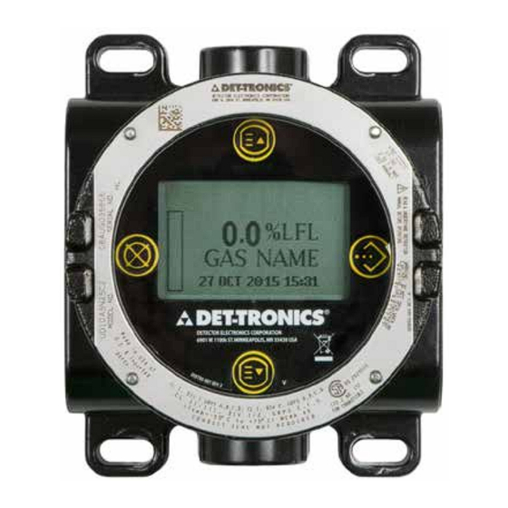
- Page 1 Instructions FlexVu® Explosion-Proof Universal Display Unit Model UD10 DCU Emulator Rev: 07/2024 95-8656...
-
Page 2: Table Of Contents
Table of Contents APPLICATION . . . . . . . . . . . . . . . . . . . . . . . . . . . . . . . . . . . . . . . 1 APPENDIX G —... - Page 3 Table of Contents APPENDIX O — UD10-DCU WITH ATX10/AC100 GAS DETECTOR ........O-1 Wiring.
-
Page 4: Application
The UD10-DCU is designed for use with most currently available The UD10-DCU Universal Display can be used with various 4-20 Det-Tronics gas detectors . Refer to the "Specifications" section of this mA gas detection devices, with or without HART . The unit provides manual for a list of compatible gas detectors . -
Page 5: Magnetic Switches
NOTE MAGNETIC SWITCHES Det-Tronics offers two magnet options for activating Four internal magnetic switches provide a non-intrusive user interface internal magnetic switches. While the two magnets can that allows navigation through the menu . See Figure 1 for switch usually be used interchangeably, the best results will locations . -
Page 6: Device Enclosure
Access To Menus CONFIGURATION OVERVIEW To access the menus, use the magnet to activate the ENTER/ The user must select the sensor mode/type manually from the UD10- SELECT button . This will display the Main Menu . DCU display . The selection options are: •... -
Page 7: Calibration Gas Concentration
CALIBRATION GAS CONCENTRATION require a gas concentration of 50% full scale . Calibration gas concentration can be viewed from the UD10-DCU menu under The calibration gas concentration is programmed from S Display Status->LON Config . downloaded to the UD10-DCU . See Table 3 for calibration gas limits . NTMOS, CGS, and PIR9400 Table 2—UD10-DCU Alarm Limits UD10-DCU Limits... -
Page 8: Logging
IMPORTANT SAFETY NOTES LOGGING Events that can be logged in the UD10-DCU include: CAUTION • Calibration (Date, time, and success Y/N are logged for detectors The wiring procedures in this manual are intended to that do not provide their own calibration logging capabilities .) ensure proper functioning of the device under normal conditions. -
Page 9: Installation
INSTALLATION If the vapor of interest is lighter than air, place the detector above the potential gas leak . Place the detector close to the floor for NOTE gases that are heavier than air . Note that air currents may cause a For complete instructions regarding wiring, installation, gas that is slightly heavier than air to rise under some conditions . -
Page 10: Wiring
WIRING COM 2 - Communication network connections: Connect to COM 1 terminals of the previous device on POWER SUPPLY REQUIREMENTS the loop, A to A and B to B . Calculate the total gas detection system power consumption rate in watts from cold start-up . Select a power supply with adequate 24 VDC - Connect the “+”... - Page 11 UD10 Sensor Connector DISPLAY UNIT FACTORY USE ONLY LON ADDRESS SELECTION SWITCHES SHIELD J3-1 2 B COM J3-2 2 A COM J3-3 SHIELD J3-4 1 B COM J3-5 1 A COM J3-6 VALUES OF ALL SWITCHES IN THE ON POSITION ARE ADDITIVE. Power Supply Connector A2509 Figure 2—Wiring Terminal Board...
-
Page 12: Lon Address Switch Setting
LON ADDRESS SWITCH SETTING DETECTOR TYPE/MODE SELECTION PROCEDURE Each device on the LON/SLC must be assigned a unique address . After power has been applied and the warm-up period is complete, This is accomplished by setting DIP switches on the module’s circuit select the UD10-DCU operating mode . -
Page 13: S 3 Configuration
CONFIGURATION Create a new DCU point with the correct LON address/point number . See Figure 4 below . Figure 4—Point Type Selection Screen 95-8656... - Page 14 The DCU configuration software supports six detector types: • Explosive • Oxygen • Universal (Automatic Calibration) • Universal (Manual Calibration) • PointWatch • DuctWatch Table 5 shows the recommended settings for each detector type . Table 5—Recommended Settings for each Detector Type Detector Type Recommended Configuration Comments...
- Page 15 Enter the appropriate data on the DCU Editor Screen . See Figure 5 . The units and range entered at S will be seen in S and the Controller, but are not sent to the UD10-DCU . It is the user’s responsibility to ensure that S matches the actual detector type .
- Page 16 UD10-DCU Input Trim Time and date for the UD10-DCU is automatically set by the EQP When the UD10-DCU is used with a detector that supports HART controller via the LON network . Changes to the time on the S communication, an automated process can be used to trim the UD10- computer will be reflected at the UD10-DCU when the controller RTC DCU input .
-
Page 17: Response Test
OPTIONAL SYSTEM TESTS DISPLAY BACKLIGHT OPERATION The following tests are available for verifying proper operation of The UD10-DCU can be programmed to turn on the backlight feature various functions of the gas detection system: of the digital display when an alarm or fault occurs or a magnetic switch is activated . -
Page 18: Troubleshooting
TROUBLESHOOTING Example: If a Fault condition is indicated on the UD10-DCU faceplate, the For a Display (UD10-DCU) related fault: nature of the fault can be determined by using the magnetic tool to Main Menu > Display Status > Fault/Status > Fault navigate to the appropriate Fault screen . - Page 19 Table 7—Troubleshooting Guide - Device Faults Device Faults Description Recommended Action Loop Fault Current loop below fault threshold Check 4-20 mA loop wiring for shorts or opens. Supply Voltage Verify proper wiring to the device and correct voltage 24 volt power supply voltage too low Fault output from the power supply.
-
Page 20: Specifications
Table 7—Troubleshooting Guide - Device Faults, Continued Device Faults Description Recommended Action Power may have been interrupted while the de- EE Fault Fault in non-volatile memory vice was updating its internal data logs. Recycle power. Sensor signal level is outside the range of the Ref ADC Sat Return to factory. -
Page 21: Electromagnetic Compatibility
* Carbon dioxide only. 5.86 ** Hydrogen sulfide only. (14.9) (13.2) (6.9) DETECTOR COMPATIBILITY— The UD10-DCU can be used with the Det-Tronics gas detectors listed in Table 8 . UNIT OF MEASUREMENT— (11.9) PPM, % LFL, % V/V, LFLM, or Mg/M 3.46 (8.8) OPERATING TEMPERATURE—... - Page 22 WIRING TERMINALS— CERTIFICATION— 14 to 18 AWG, 2 .5-0 .75 mm wire can be used . For complete approval details, refer to the appropriate Appendix: CONDUIT ENTRIES— 3/4” NPT or M25 . ® ENCLOSURE MATERIAL— APPROVED Epoxy coated aluminum or 316 stainless steel . Appendix A –...
-
Page 23: Device Repair And Return
DEVICE REPAIR AND RETURN ORDERING INFORMATION Prior to returning devices, contact the nearest local Detector Sensor module, transmitter module and termination boxes (if used) Electronics office so that a Return Material Authorization (RMA) must be ordered separately . number can be assigned . A written statement describing the malfunction must accompany the returned device or component Refer to the UD10-DCU Model Matrix for ordering details . -
Page 24: Type Approval
UD10-DCU MODEL MATRIX MODEL DESCRIPTION UD10-DCU Universal Display Unit TYPE MATERIAL Aluminum Stainless Steel (316) TYPE THREAD TYPE 5 Port, Metric M25 5 Port, 3/4" NPT TYPE OUTPUTS Relay, 4-20 mA, RS485, HART EQP / DCU Emulator TYPE APPROVAL INMETRO (Brazil) Russia FM/CSA/ATEX/CE/IECEx TYPE... -
Page 25: Appendix A - Fm Approval Description
APPENDIX A FM APPROVAL DESCRIPTION Class I, Div . 1, Groups B, C & D T5; Class I, Div . 2, Groups B, C & D T4; Class I, Zone 1/2 AEx d IIC T5; Class II/III, Div . 1/2, Groups E, F & G . T amb –40°C to +75°C NEMA/Type 4X, IP66 Conduit seal not required . -
Page 26: Appendix B - Csa Certification Description
APPENDIX B CSA CERTIFICATION DESCRIPTION CSA 2029512 . Class I, Div . 1, Groups B, C & D T5; Class I, Div . 2, Groups B, C & D T4; Class II/III, Div . 1/2, Groups E, F & G T5 . (Tamb = –40°C to +75°C) Type 4X Conduit seal not required . -
Page 27: Appendix C - Atex Approval Description
• The UD10 and AV10 control unit complies with EN 60079-29-4 when connected to a Detector Head that also has been evaluated to EN 60079-29-4 . • Flameproof joints are not user serviceable; contact Det-Tronics . • The actual enclosure must provide a maximum measured reference pressure of 15 bar measured according to EN 60079-1:2014, §16 •... - Page 28 EN 60079-29-1 standard . • The actual enclosure must provide a maximum measured reference pressure of 15 bar measured according to EN 60079-1:2014, §15 . • Flameproof joints are not user serviceable; contact Det-Tronics Service . 95-8656...
- Page 29 • The UD10 and AV10 control unit complies with IEC 60079-29-4 when connected to a Detector Head that also has been evaluated to IEC 60079-29-4 . • Flameproof joints are not user serviceable; contact Det-Tronics . • The actual enclosure must provide a maximum measured reference pressure of 15 bar measured according to IEC 60079-1:2014, §16 •...
- Page 30 IEC 60079-29-1 standard . • The actual enclosure must provide a maximum measured reference pressure of 15 bar measured according to IEC 60079-1:2014, §15 . • Flameproof joints are not user serviceable; contact Det-Tronics Service . 95-8656...
-
Page 31: Appendix E - Additional Approvals
• The UD10 and AV10 control unit complies with IEC 60079-29-4 when connected to a Detector Head that also has been evaluated to IEC 60079-29-4 . • Flameproof joints are not user serviceable; contact Det-Tronics . • The actual enclosure must provide a maximum measured reference pressure of 15 bar measured according to IEC 60079-1:2014, §16 •... -
Page 32: Wiring
APPENDIX F UD10-DCU with GT3000 TOXIC GAS DETECTOR NOTE For complete information regarding the GT3000 Gas Detector, refer to instruction manual 95-8616. WIRING UD10-DCU with GT3000/C706X 4000 3500 3000 Wire Size 2500 2000 1500 1000 Power Supply Voltage Notes: Maximum recommended cable length from power source to UD10 is 2000 feet. Maximum recommended cable length from UD10 to sensor/STB termination box is 2000 feet. -
Page 33: Orientation
SEE NOTE 1 BLACK UD10 DISPLAY UNIT Sensor Connector SENSOR TERMINATION BOX GREEN SHIELD J3-1 2 B COM J3-2 2 A COM J3-3 SHIELD J3-4 1 B COM J3-5 1 A COM J3-6 GT3000 GAS DETECTOR Power Supply Connector NOTE 1 GROUND THE SHIELD AT THE DISPLAY UNIT END ONLY. -
Page 34: Calibration
CALIBRATION From UD10-DCU Using the magnet to activate the switches on the UD10-DCU GT3000 WITH TOXIC GAS SENSOR display, navigate to the "Calibration" menu . Main Menu From GT3000: Process Vars Using the magnet, activate the magnetic calibration switch on Display Status Device Cal Calibration... -
Page 35: Menu Structure
GT3000 WITH OXYGEN SENSOR From UD10-DCU Using the magnet to activate the switches on the UD10-DCU From GT3000: display, navigate to the Calibration menu . Using the magnet, activate the magnetic calibration switch on Main Menu the GT3000 . The green LED turns to yellow . Process Vars Display Status Device Cal... -
Page 36: Appendix G - Ud10-Dcu With Pir9400
APPENDIX G UD10-DCU with PIR9400 POINTWATCH IR GAS DETECTOR NOTE For complete information regarding the PIR9400 Gas Detector, refer to instruction manual 95-8440. WIRING UD10-DCU with PIR9400 4000 3500 3000 Wire Size 2500 2000 1500 1000 Power Supply Voltage Notes: Maximum recommended cable length from power source to UD10 is 2000 feet. -
Page 37: Installation Notes
PIRTB JUNCTION BOX PIR9400 DETECTOR UD10 DISPLAY UNIT SEE NOTE 1 GREEN Sensor Connector SPARE CHASSIS YELLOW 4 – 20 4 – 20 WHITE BLACK SHIELD J3-1 2 B COM J3-2 2 A COM J3-3 SHIELD J3-4 1 B COM J3-5 1 A COM J3-6... -
Page 38: Changing Operating Modes
CHANGING OPERATING MODES CALIBRATE SWITCH HOLD CALIBRATION MAGNET When used with a PIR9400, the operating mode of the UD10-DCU AT OUTSIDE BASE OF JUNCTION REMOTE LED BOX AT THIS LOCATION must be changed from “HART Device” to “PIR9400” mode . Refer to TO ACTIVATE CALIBRATION SWITCH the “Startup”... -
Page 39: Appendix H - Ud10-Dcu With Model Pirecl
APPENDIX H UD10-DCU with MODEL PIRECL NOTE For complete information regarding the PIRECL Gas Detector, refer to instruction manual 95-8526. WIRING UD10-DCU with PIRECL/OPECL/NTMOS/CGS 4000 3500 3000 Wire Size 2500 2000 1500 1000 Power Supply Voltage Notes: Maximum recommended cable length from power source to UD10 is 2000 feet. Maximum recommended cable length from UD10 to sensor/STB termination box is 2000 feet. -
Page 40: Orientation
MODEL PIRECL BLACK 24 VDC – 24 VDC + CALIBRATE 24 VDC – 24 VDC + 4-20 MA + WHITE 4-20 MA – RS-485 B RS-485 A RELAY POWER (RED) UD10 WIRING TO OPTIONAL FAULT (ORANGE) DISPLAY UNIT RELAY BOARD Sensor Connector LOW ALARM (WHITE) NO USER CONNECTION... -
Page 41: Calibration
CALIBRATION To initiate calibration from the PIRECL while monitoring calibration using the UD10-DCU display: To initiate calibration of the PIRECL from the UD10-DCU Display: Using the magnet, activate the magnetic calibration switch on Using the magnet to activate the switches on the UD10-DCU the PIRECL detector . -
Page 42: Menu Structure
MENU STRUCTURE UD10-DCU with Model PIRECL Refer to the following menu when using the UD10-DCU’s LCD display and internal magnetic switches . MENU HELP Status menus only allow the user to view the data. The Setup menus allow the user to both view and edit the data. 95-8656... -
Page 43: Wiring
APPENDIX I UD10-DCU with OPEN PATH ECLIPSE MODEL OPECL NOTE For complete information regarding the OPECL Gas Detector, refer to instruction manual 95-8556. WIRING UD10-DCU with PIRECL/OPECL/NTMOS/CGS 4000 3500 3000 Wire Size 2500 2000 1500 1000 Power Supply Voltage Notes: Maximum recommended cable length from power source to UD10 is 2000 feet. - Page 44 MODEL OPECL BLACK 24 VDC – 24 VDC + CALIBRATE 24 VDC – 24 VDC + 4-20 MA + WHITE 4-20 MA – RS-485 B RS-485 A Sensor Connector UD10 DISPLAY UNIT NO USER CONNECTION SHIELD J3-1 2 B COM J3-2 2 A COM J3-3...
-
Page 45: Orientation
ORIENTATION CALIBRATION OPECL modules must be affixed to a solid, non-vibrating structure To initiate zero calibration of the OPECL from the UD10-DCU capable of supporting a minimum of 100 lbs (46 kg), located within Display: the system’s rated separation distance . See examples below . 1 . -
Page 46: Opecl Transmitter Lamp Fault Condition
OPECL TRANSMITTER LAMP To initiate zero calibration from the OPECL: FAULT CONDITION 1 . Using the magnet, activate the magnetic calibration switch on the If the OPECL system experiences a Transmitter (Tx) Lamp Fault OPECL receiver . See the figure below . The green LED will turn condition, the UD10-DCU display will not indicate a fault condition red . -
Page 47: Wiring
APPENDIX J UD10-DCU with NTMOS H S SENSOR NOTE For complete information regarding the NTMOS Gas Detector, refer to instruction manual 95-8604. WIRING UD10-DCU with PIRECL/OPECL/NTMOS/CGS 4000 3500 3000 Wire Size 2500 2000 1500 1000 Power Supply Voltage Notes: Maximum recommended cable length from power source to UD10 is 2000 feet. Maximum recommended cable length from UD10 to sensor/STB termination box is 2000 feet. - Page 48 ORANGE SEE NOTE 1 GREY YELLOW BLACK WHITE UD10 DISPLAY UNIT Sensor Connector SHIELD J3-1 2 B COM J3-2 2 A COM J3-3 NTMOS SHIELD J3-4 SENSOR 1 B COM J3-5 1 A COM J3-6 NOTE 1 GREY AND ORANGE WIRES FOR FACTORY USE ONLY. Power Supply Connector NOTE 2 UD10 HOUSING MUST BE ELECTRICALLY...
-
Page 49: Orientation
The NTMOS sensor must be calibrated using 50 ppm H S in air (never use H S in nitrogen) . Det-Tronics provides two acceptable sources of 50 ppm H calibration gas for use with NTMOS sensors . WARNING FLEXVU UD10... -
Page 50: Calibration Procedure
2 . Activate “Execute” (Enter/Select) to begin the zero calibration . 3 . The UD10-DCU will display “Waiting for Zero” on the main display screen . 4 . When zero calibration is complete (approximately one minute), the UD10-DCU will display “Waiting for Span” on the main display screen . -
Page 51: Wiring
APPENDIX K UD10-DCU with C706X TOXIC GAS SENSOR NOTE For complete information regarding the C7064E H2S Gas Sensor, refer to instruction manual 95-8396. For the C7067E Chlorine Gas Sensor, refer to instruction manual 95-8439. WIRING UD10-DCU with GT3000/C706X 4000 3500 3000 Wire Size 2500... - Page 52 BLACK UD10 DISPLAY UNIT GREEN Sensor Connector SEE NOTE 1 SHIELD J3-1 2 B COM C706X SENSOR J3-2 2 A COM J3-3 SHIELD J3-4 1 B COM J3-5 1 A COM J3-6 NOTE 1 CONNECT THE GREEN SENSOR LEAD TO THE CHASSIS GROUND LUG ON THE INSIDE BOTTOM OF THE DISPLAY ENCLOSURE.
-
Page 53: Installation
INSTALLATION INSTALLATION AND WIRING PROCEDURE 1 . Determine the best mounting locations for the detectors . WIRING REQUIREMENTS 2 . Install the C706X sensor within the proper opening in the UD10- The simplest installation involves installing the sensor into one of the DCU or STB junction box . -
Page 54: Calibration
CALIBRATION MENU STRUCTURE To initiate calibration of the C706X sensor from the UD10-DCU UD10-DCU with C706X Series Sensor Display: Refer to the following menu when using the UD10-DCU’s LCD 1 . Using the magnet to activate the switches on the UD10-DCU display and internal magnetic switches . -
Page 55: Wiring
APPENDIX L UD10-DCU with MODEL CGS COMBUSTIBLE GAS SENSOR WIRING UD10-DCU with PIRECL/OPECL/NTMOS/CGS 4000 3500 3000 Wire Size 2500 2000 1500 1000 Power Supply Voltage Notes: Maximum recommended cable length from power source to UD10 is 2000 feet. Maximum recommended cable length from UD10 to CGS sensor is 500 feet (using 16 AWG, 1.5 mm2 cable minimum). - Page 56 SET ALL SWITCHES TO THE “ON” POSITION (FACTORY DEFAULT SETTING) CGS INTERFACE BOARD TERMINAL J11 FOR FACTORY USE ONLY LOCATED INSIDE UD10 HOUSING CONNECT TO UD10 MODULE VIA CABLE (FACTORY INSTALLED) CONNECT CGS SENSOR TO TERMINAL J10 CGS INTERFACE BOARD NOTE 1 REMOVE UD10 ELECTRONICS MODULE FOR ACCESS TO CGS INTERFACE BOARD (NO TOOLS REQUIRED).
-
Page 57: Installation
INSTALLATION CALIBRATION NOTE WIRING REQUIREMENTS For maximum calibration accuracy, allow a new sensor to The simplest installation involves installing the sensor into one of the operate under power for several hours (minimum one hour) to UD10-DCU openings and connecting the wiring directly to the CGS ensure a stable output before performing calibration. -
Page 58: K-Factor
K FACTOR Determining Sensor Life Remaining At the time of calibration, the UD10-DCU logs the sensor mV signal . If the system will be detecting a gas/vapor other than the gas used in This value can be used for determining the approximate sensor life the actual calibration process, a conversion K-Factor must be used . -
Page 59: Wiring
APPENDIX M UD10-DCU with MODEL 505 TRANSMITTER / CGS SENSOR NOTE For complete information regarding the Model 505 Transmitter, refer to instruction manual 95-8472. WIRING UD10-DCU with PIRECL/OPECL/NTMOS/CGS 4000 3500 3000 Wire Size 2500 2000 1500 1000 Power Supply Voltage Notes: Maximum recommended cable length from power source to UD10 is 2000 feet. -
Page 60: Installation
Sensor Connector UD10 DISPLAY UNIT MODEL 505 TRANSMITTER SHIELD J3-1 2 B COM J3-2 2 A COM J3-3 SHIELD J3-4 1 B COM J3-5 1 A COM J3-6 Power Supply Connector CONNECT KEYED SENSOR PLUG TO PIN CONNECTOR NOTES 1. SHIELDED SENSOR WIRING CABLE REQUIRED. 2. -
Page 61: Calibration
CALIBRATION NOTE ZERO/SPAN SWITCH For maximum calibration accuracy, allow a new sensor ZERO ADJUST SENSOR VOLTAGE ADJUST to operate under power for several hours (minimum SPAN ADJUST one hour) to ensure a stable output before performing CAL/NORM SWITCH CALIBRATE LED calibration. -
Page 62: Menu Structure
MENU STRUCTURE UD10-DCU with Model 505 / CGS Sensor Refer to the following menu when using the UD10-DCU’s LCD display and internal magnetic switches . MENU HELP Status menus only allow the user to view the data. The Setup menus allow the user to both view and edit the data. 95-8656... -
Page 63: Operation
APPENDIX N UD10-DCU with GENERIC 4-20 mA SENSORS NOTE For complete information regarding installation, wiring, and calibration of the sensor, refer to the instruction manual provided by the sensor manufacturer. OPERATION ALARMS The Low, High and Auxiliary alarm levels are independently field The UD10-DCU can be used with generic sensors that generate adjustable . -
Page 64: Wiring
APPENDIX O UD10-DCU with FLEXSONIC ACOUSTIC GAS DETECTOR NOTE For complete information regarding the FlexSonic Acoustic Detector, refer to instruction manual 95-8657. WIRING UD10-DCU with FlexSonic Acoustic 4000 3500 3000 Wire Size 2500 2000 1500 1000 Power Supply Voltage Notes: Maximum recommended cable length from power source to UD10-DCU is 2000 feet. - Page 65 ATX10 TRANSMITTER INTERFACE BOARD TO SOFTWARE CONFIGURATOR ORANGE GRAY BLACK SENSOR POWER GREEN AND OUTPUT Sensor Connector IS GROUND UD10-DCU DISPLAY UNIT SHIELD J3-1 2 B COM J3-2 2 A COM J3-3 SHIELD AC100 J3-4 ACOUSTIC 1 B COM J3-5 SENSOR 1 A COM J3-6...
-
Page 66: Menu Structure
ALARM/FAULT STATUS ALARM MODE A L A RM BAS I C 59 DB ALARM LEVEL DATE AND TIME 09 N OV 2 01 5 08 :5 2 A2697 Figure 6-1—UD10-DCU Screen When Used with FlexSonic Acoustic Detector AUDIBLE RANGE 4X 30 BANDS = 120 BANDS ULTRASONIC RANGE 8X 3 BANDS = 24 BANDS MAXIMUM AMPLITUDE = 139 dB... -
Page 67: Appendix P - Ud10-Dcu With Model Pirduct
APPENDIX P UD10-DCU with MODEL PIRDUCT NOTE For complete information regarding the PIRDUCT Gas Detector, refer to instruction manual 95-8573. WIRING UD10-DCU with PIRDUCT 4000 3500 3000 Wire Size 2500 2000 1500 1000 Power Supply Voltage Notes: Maximum recommended cable length from power source to UD10-DCU is 2000 feet. Maximum recommended cable length from UD10-DCU to PIR9400/PIRTB termination box is 2000 feet. -
Page 68: Installation Notes
PIRTB JUNCTION BOX PIRDUCT DETECTOR UD10-DCU SEE NOTE 1 DISPLAY UNIT GREEN Sensor Connector SPARE CHASSIS YELLOW 4 – 20 4 – 20 WHITE BLACK SHIELD J3-1 2 B COM J3-2 2 A COM J3-3 SHIELD J3-4 1 B COM J3-5 1 A COM J3-6... -
Page 69: Calibration
CHANGING OPERATING MODES UD10-DCU mA Output During Calibration (UD10 with PIR9400) When used with a PIRDUCT, the operating mode of the UD10-DCU must be changed from “HART Device” to “PIRDUCT” mode . Refer to Standard Replicate UD10-DCU Display Reading the “Startup” section of this manual for details . Mode Mode Waiting for Zero... -
Page 70: Menu Structure
MENU STRUCTURE UD10-DCU with PIRDUCT Gas Detector Refer to the following menu when using the UD10-DCU’s LCD display and internal magnetic switches . MENU HELP Status menus only allow the user to view the data. The Setup menus allow the user to both view and edit the data. 95-8656... -
Page 71: Wiring
APPENDIX Q UD10-DCU with MODEL PIRECL CARBON DIOXIDE DETECTOR NOTE For complete information regarding the PIRECL CO Gas Detector, refer to instruction manual 95-8676. WIRING UD10-DCU with PIRECL 4000 3500 3000 Wire Size 2500 2000 1500 1000 Power Supply Voltage Notes: Maximum recommended cable length from power source to UD10-DCU is 2000 feet. -
Page 72: Orientation
MODEL PIRECL BLACK 24 VDC – 24 VDC + CALIBRATE 24 VDC – 24 VDC + 4-20 MA + WHITE 4-20 MA – RS-485 B RS-485 A UD10-DCU RELAY POWER (RED) DISPLAY UNIT WIRING TO OPTIONAL FAULT (ORANGE) RELAY BOARD Sensor Connector NO USER CONNECTION LOW ALARM (WHITE) -
Page 73: Calibration
CALIBRATION To initiate calibration from the PIRECL CO while monitoring calibration using the UD10-DCU display: To initiate calibration of the PIRECL CO from the UD10-DCU Display: Using the magnet, activate the magnetic calibration switch on the PIRECL CO detector . See Figure below . The LED turns Using the magnet to activate the switches on the UD10-DCU from green to red . -
Page 74: Menu Structure
MENU STRUCTURE UD10-DCU with Model PIRECL CO Gas Detector Refer to the following menu when using the UD10-DCU’s LCD display and internal magnetic switches . MENU HELP Status menus only allow the user to view the data. The Setup menus allow the user to both view and edit the data. 95-8656... -
Page 75: Appendix R - Ud10-Dcu With Ls2000 Line Of Sight Gas Detector
APPENDIX R UD10-DCU with LS2000 LINE OF SIGHT GAS DETECTOR NOTE For complete information regarding the LS2000 Gas Detector, refer to instruction manual 95-8714. WIRING UD10-DCU with LS2000 4000 3500 3000 Wire Size 2500 2000 1500 1000 Power Supply Voltage Notes: Maximum recommended cable length from power source to UD10-DCU is 2000 feet. - Page 76 LS2000 RECEIVER WITHOUT RELAYS 0V COM SPARE +24 VDC 0V COM 0V COM +24 VDC SHIELD SHIELD INTR B INTR A INTR GND SHIELD SHIELD RS-485 A RS-485 B –mA HART UD10-DCU DISPLAY UNIT Sensor Connector SHIELD J3-1 2 B COM J3-2 2 A COM J3-3...
-
Page 77: Installation
INSTALLATION CALIBRATION LS2000 modules must be affixed to a solid, non-vibrating structure To initiate zero calibration of the LS2000 from the UD10-DCU capable of supporting a minimum of 100 lbs (46 kg), located within Display: the system’s rated separation distance . See examples below . 1 . -
Page 78: Menu Structure
MENU STRUCTURE To initiate zero calibration from the LS2000: 1 . Using the magnet, activate the magnetic calibration switch on the UD10 with LS2000 Line of Sight Gas Detector LS2000 receiver . See Figure below . The green LED will turn red . Refer to the following menu when using the UD10-DCU’s LCD display and internal magnetic switches . - Page 79 Leak Detector IR Flame Detector Combustible Gas Detector with GT3000 Toxic Gas Detector Safety System Corporate Office Phone: +1 952.941.5665 6901 West 110 Street Toll-free: +1 800.765.3473 Minneapolis, MN 55438 USA Fax: 952.829.8750 www.det-tronics.com det-tronics@carrier.com © 2024 Detector Electronics, LLC.
Need help?
Do you have a question about the UD10 DCU Emulator and is the answer not in the manual?
Questions and answers