
Subscribe to Our Youtube Channel
Related Manuals for Det-Tronics UD10


Summary of Contents for Det-Tronics UD10
- Page 1 Instructions 95-8661 ® FlexVu Explosion-Proof Universal Display Unit Model UD10 Rev: 2/13 95-8661...
-
Page 2: Table Of Contents
. . . . . . . . . . . . . . . . . . . . . . . . . . . . . . . E-1 appEnDiX M — UD10 WitH MoDEl 505/cGS . . . . . . . . .M-1 Wiring . -
Page 3: Application
Modbus RS485 or ™ Fieldbus foundation directly to the UD10, or remotely located using a sensor termination box. Three alarm relays and one fault relay Visible Outputs: Backlit LCD display The UD10 features non-intrusive calibration. A magnet... - Page 4 Table 1—Range and Default Values for Alarms and Calibration Gas Concentration UD10 ALARM DATA CALibRATiON Gas Detector High Alarm Value Low Alarm Value Aux alarm Value Cal Gas Range 10-90% 5-50% 5-90% 30-90% GT3000-- Hydrogen Sulfide Default Range 10-90% 5-50%...
-
Page 5: Hart Communication
To actuate a magnetic switch, lightly touch the magnet HART COmmUNICATION to the viewing window of the UD10 directly over the A HART interface provides device status information switch icon on the faceplate. and field programming capability. CautIon mAgNETIC SwITCHES... -
Page 6: Relays
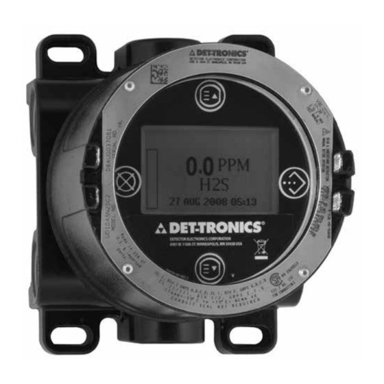
POSITIVE 1N4004 DCV LOADS DEvICE DISplAy TYPICAL TYPICAL LA20A The UD10 is provided with a 160 x 100 dot matrix backlit NEGATIVE – A0179 B0179 LCD display. See Figure 1. Figure 2—Transient Suppression for inductive Loads During normal operation, the LCD continuously displays the detected gas level, gas type, and units of measurement. -
Page 7: Logging
• General fault before wiring the system. Installation must be done by a properly trained person. Alarms that are logged in the UD10 for gas detector inputs include: CautIon This product has been tested and approved • High gas alarm... -
Page 8: Installation
Table 2. If the UD10 faceplate is not correctly oriented, it can be rotated at 90 degree increments by pulling the electronic module from the four mounting posts that secure it to the junction box and repositioning it as desired. -
Page 9: Wiring
Appendix for additional information. • For a non-isolated 4-20 mA loop, set jumper plug as The maximum cable length from power source to UD10 is shown in Figure 4. This applies +24 Vdc to P1-3 via an 2000 feet. Maximum cable length from UD10 to sensor internal connection to terminals P2-2 and P2-5. -
Page 10: Wiring Procedure
(wiring, calibration, HART menus, etc.) is covered Figure 11 shows a UD10 Wired to a PLC with a 4-20 mA in an Appendix that is dedicated to that device. Isolated Sourcing Output. - Page 11 Sensor Connector HIGH ALARM COM J4-1 4-20 mA + P1-3 HIGH ALARM NC J4-2 HIGH ALARM NO J4-3 Output 4-20 mA – P1-2 Loop AUX ALARM COM J4-4 Connector SHIELD P1-1 J4-5 AUX ALARM NC AUX ALARM NO J4-6 J4-7 LOW ALARM COM J4-8 Fieldbus...
- Page 12 Notes: Resistor may be external if voltage input card is used. Sinking resistance at PLC must be 250 ohms minimum C2439 for HART communication. Figure 9—UD10 Wired to PLC using 3-Wire Shielded Cable with 4-20 mA Non-isolated Sourcing Output 95-8661...
- Page 13 Notes: Resistor may be external if voltage input card is used. Sinking resistance at PLC must be 250 ohms minimum D2440 for HART communication. Figure 10—UD10 Wired to PLC using 4-Wire Shielded Cable with 4-20 mA Non-isolated Sourcing Output UD10 DISPLAY UNIT Sensor Connector...
-
Page 14: Startup
SELECT button to go to the next screen, then use If using a PIR9400, note that changing the gas the PREVIOUS or NExT buttons to toggle between type on the UD10 does not change the gas type at Y and N. Once the chosen input is selected, use the PIR9400. This change is made using a switch the ENTER/SELECT button to enter the selection. - Page 15 When the UD10 is used with a detector that supports Upon entering Input Loop Cal, the UD10 commands HART communication, the output of the detector should the detector to output 4 mA, and then automatically be calibrated first. calibrates its own input. The UD10 then commands the detector to output 20 mA and subsequently calibrates its own input.
- Page 16 HART enabled time and date stamp). detectors.) pASSwORD pROTECTION Main Menu The UD10 allows the use of a password for restricting Process Vars changes to configuration parameters and limiting Display Test Display Status access to safety critical commands.
-
Page 17: Troubleshooting
Example: If a Fault condition is indicated on the UD10 faceplate, For a Display (UD10) related fault: the nature of the fault can be determined by using Main Menu > Display Status > Fault/Status > Fault the magnetic tool to navigate to the appropriate Fault screen. - Page 18 Table 4—Troubleshooting Guide - Device Faults Device Faults Description Recommended Action Loop Fault Current loop below fault threshold Check 4-20 mA loop wiring for shorts or opens. Supply Voltage Verify proper wiring to the device and correct 24 volt power supply voltage too low Fault voltage output from the power supply.
- Page 19 Table 4—Troubleshooting Guide - Device Faults, Continued Device Faults Description Recommended Action Power may have been interrupted while the device EE Fault Fault in non-volatile memory was updating its internal data logs. Recycle power. Sensor signal level is outside the range of the AD Ref ADC Sat Return to factory.
-
Page 20: Specifications
–55°C to +75°C. noTe Appropriate relays will be activated when a fault HUMiDiTy RANGE— or alarm occurs. 5 to 95% RH (Det-Tronics verified). CURRENT OUTPUT— ELECTRO-MAGNETiC COMPATibiLiTy— Linear isolated 4-20 mA output with HART. EMC Directive 2004/108/EC 3.8 mA indicates calibrate mode. - Page 21 5.86 (14.9) 11.28 (28.7) R0.175 A2442 Figure 12—Dimensions of UD10 with GT3000 in inches (Centimeters) CONDUiT ENTRiES— WARRANTy— 3/4” NPT or M25. 12 months from date of installation or 18 months from date of shipment, whichever occurs first. ENCLOSURE MATERiAL—...
-
Page 22: Device Repair And Return
Minneapolis. Certified SIL 2 Capable. noTe specific information regarding safety It is highly recommended that a spare be kept on certification, refer to the Model UD10 Safety Reference hand for field replacement to ensure continuous Manual (form 95-8668). protection. 95-8661... -
Page 23: Ordering Information
(if used) must be ordered separately. 005003-001 Lubriplate grease, 1 oz. 010268-001 Gas Inspector CD Refer to the UD10 Model Matrix for ordering details. 010204-001 W6300G1003 Gas Inspector Connector *NEMA 4/IP66 rating requires addition of non-hardening REplACEmENT pARTS thread sealant or Teflon tape. -
Page 24: Appendix A - Fm Approval Description
Factory Mutual Research. noTe Consideration must be given to overall Gas System Performance Requirements. WarnIng When a sensor/detector is connected directly to the UD10 housing, the lower ratings of the two devices will prevail. 95-8661... -
Page 25: Appendix B - Csa Certification Description
Performance verified in accordance with: CSA C22.2 #152. noTe Consideration must be given to overall Gas System Performance Requirements. WarnIng When a sensor/detector is connected directly to the UD10 housing, the lower ratings of the two devices will prevail. 95-8661... -
Page 26: Appendix C - Atex Approval Description
EN 60079-29-1 and EN 50241-1/-2. Special Conditions for Safe Use (‘x’): The UD10 control unit complies with EN 60079-29-1 and EN 50241-1/-2 only when connected to a Detector Head that also has been evaluated to EN 60079-29-1 and EN 50241-1/-2. -
Page 27: Appendix D - Iec Approval Description
Performance verified in accordance with: IEC 60079-29-1 Special Conditions for Safe Use (‘x’): The UD10 control unit complies with IEC 60079-29-1 when connected to a Detector Head with an IEC certificate of conformity to IEC 60079-29-1. noTe Consideration must be given to overall Gas System Performance Requirements. -
Page 28: Wiring
AppenDix e USINg A HANDHElD HART DEvICE CONNECTED TO THE UD10’S 4-20 mA OUTpUT (UD10 wITH ANy DETECTOR) noTe Refer to the front of this manual for complete information regarding installation, wiring and startup of the UD10. WirinG UD10 DISPLAY UNIT... - Page 29 5) AUX Alarm Calibration Active ON/OFF 2) Tag xxxxx 6) Analog Output xxxxx 3) Descriptor xxxxx Warm Up ON/OFF DET-TRONICS 7) Upper Range Value xxxxx Low Alarm ON/OFF 4) Message xxxxx 8) Lower Range Value xxxxx Aux Alarm ON/OFF 5) Final Asmbly Num...
- Page 30 2000 1500 1000 Power Supply Voltage Notes: Maximum cable length from power source to UD10 is 2000 feet. Maximum cable length from UD10 to sensor/STB termination box is 2000 feet. BLACK UD10 DISPLAY UNIT GREEN Sensor Connector SEE NOTE 1...
- Page 31 UNIT END ONLY. NOTE 2 HOUSINGS MUST BE ELECTRICALLY C2401 CONNECTED TO EARTH GROUND. UD10 Wired to GT3000 Detector with Sensor Termination box orientAtion liVe mAintenAnce The device must be mounted in a vertical position only, noTe with the GT3000 pointing down.
- Page 32 LED on the detector is flashing. 2. The UD10 will display “Waiting for Zero” on the main 7. When the UD10 displays “Remove Cal Gas” on the display screen, with the yellow LED on the detector screen and the LEDs on the detector housing are housing illuminated continuously.
- Page 33 If using bottled 20.9% oxygen, apply immediately. 3. The UD10 will display “Waiting for Zero” on the The UD10 displays “Waiting for Span” on the main display screen, with the yellow LED on the screen.
- Page 34 PROCESS VARS GENERAL INFO GAS NAME XXXXX MANUFACTURER GAS VALUE X.XX MODEL UD-10 HIGH ALARM XXXXX LOW ALARM DESCRIPTON XXXXX 6901 WEST 110TH STREET AUX ALARM DATE DD/MMM/YYYY MINNEAPOLIS, MN 55438 ANALOG INPUT X.XX MA MESSAGE XXXXX ANALOG OUTPUT X.XX MA GENERAL INFO FINAL ASSY NUM XXXXX...
- Page 35 2000 1500 1000 Power Supply Voltage Notes: Maximum cable length from power source to UD10 is 2000 feet. Maximum cable length from UD10 to PIR9400/PIRTB termination box is 2000 feet. UD10 DISPLAY UNIT Sensor Connector PIR9400 POINTWATCH Output Loop YELLOW...
-
Page 36: Detector
INSIDE BOTTOM OF THE PIRTB. NOTE 2 HOUSINGS MUST BE ELECTRICALLY A2556 CONNECTED TO EARTH GROUND. UD10 Wired to PiR9400 with PiRTb Termination box instAllAtion notes orientAtion It is highly recommended that the pIR9400 be installed in the horizontal position. The detector... -
Page 37: Changing Operating Modes
1. Using the magnet to activate the switches on the UD10 display, navigate to the “Calibration” menu. 3. The UD10 will then display “Waiting for Gas” on the Main Menu screen, while the LED at the PIRTB is flashing red. - Page 38 Refer to the following menu when using the UD10’s LCD display and internal magnetic switches. When connecting a HART Communicator to the UD10’s 4-20 mA output, refer to the “UD10 HART” menu in Appendix E. menu HeLp Status menus only allow the user to view the data.
- Page 39 GENERAL INFO PROCESS VARS MANUFACTURER MODEL UD-10 GAS NAME XXXX GAS VALUE X.XX XXXXX HIGH ALARM DESCRIPTOR XXXXX 6901 WEST 110TH STREET DATE DD/MMM/YYYY MINNEAPOLIS, MN 55438 LOW ALARM AUX ALARM MESSAGE XXXXX FINAL ASSY NUM XXXXX ANALOG INPUT X.XX MA ANALOG OUTPUT X.XX MA DEVICE ID...
-
Page 40: Wiring
UD10 with PIRECL/OPECL/Model 505/NTMOS 4000 3500 3000 Wire Size 2500 2000 1500 1000 Power Supply Voltage Notes: Maximum cable length from power source to UD10 is 2000 feet. Maximum cable length from UD10 to detector/STB termination box is 2000 feet. 95-8661... -
Page 41: Orientation
UD10 HOUSING MUST BE ELECTRICALLY Power Supply Connector CONNECTED TO EARTH GROUND. C2404 Model PiRECL Wired Directly to UD10 orientAtion It is highly recommended that the pIRECl be installed in the horizontal position. The detector is not position-sensitive in terms of its ability to detect gas. -
Page 42: Calibration
1. Using the magnet to activate the switches on the The LED turns from green to red. UD10 display, navigate to the “Calibration” menu. 2. The UD10 will display “Waiting for Zero” on the main display screen, with a solid red LED on the PIRECL Main Menu housing illuminated. - Page 43 Refer to the following menu when using the UD10’s LCD display and internal magnetic switches. When connecting a HART Communicator to the UD10’s 4-20 mA output, refer to the “UD10 HART” menu in Appendix E. menu HeLp Status menus only allow the user to view the data.
- Page 44 PROCESS VARS GAS NAME XXXXXX GENERAL INFO GAS VALUE X.XX HIGH ALARM MANUFACTURER 6901 WEST 110TH STREET LOW ALARM MODEL UD-10 MINNEAPOLIS, MN 55438 HGH ALARM NE/NDE AUX ALARM XXXXX ANALOG INPUT X.XX MA DESCRIPTOR XXXXX ALARM SETTING NE-NORMALY ENERGIZED ANALOG OUTPUT X.XX MA DATE...
- Page 45 UD10 with PIRECL/OPECL/Model 505/NTMOS 4000 3500 3000 Wire Size 2500 2000 1500 1000 Power Supply Voltage Notes: Maximum cable length from power source to UD10 is 2000 feet. Maximum cable length from UD10 to detector/STB termination box is 2000 feet. 95-8661...
- Page 46 RS485 B FAULT NO J4-12 MODBUS Connector NOTE 1 INTERNAL JUMPER REQUIRED FOR NON-ISOLATED CURRENT OUTPUT (SINGLE POWER SUPPLY). Power Supply Connector NOTE 2 UD10 HOUSING MUST BE ELECTRICALLY CONNECTED TO EARTH GROUND. C2405 Model OPECL Wired Directly to UD10 95-8661...
- Page 47 Display Test Device Test 2. Activate “Execute” (Enter/Select) to start calibration. 3. The UD10 will display “Waiting for Zero” on the main display screen, with a solid red LED on the OPECL housing illuminated. 4. After the calibration is successfully completed, the UD10 automatically returns to the normal display with the green LED illuminated on the OPECL housing.
- Page 48 4 mA. The OPECL system is still fully functional and able to detect 2. The UD10 will display “Waiting for Zero” on the main gas. If a gas alarm condition should occur, the alarm display screen, with a solid red LED on the OPECL condition will override the Tx Lamp Fault condition.
- Page 49 PROCESS VARS GENERAL INFO GAS NAME XXXXXXX MANUFACTURER GAS VALUE X.XX MODEL UD-10 HIGH ALARM XXXXX GENERAL INFO LOW ALARM DESCRIPTOR XXXXX 6901 WEST 110TH STREET AUX ALARM DATE DD/MMM/YYYY MINNEAPOLIS, MN 55438 MANUFACTURER ANALOG INPUT X.XX MA MESSAGE XXXXX MODEL OPECL_RX ANALOG OUTPUT...
-
Page 50: Wiring
1500 1000 Power Supply Voltage Notes: Maximum cable length from power source to UD10 is 2000 feet. Maximum cable length from UD10 to detector/STB termination box is 2000 feet. instAllAtion notes noTe For non-HART applications, the nTMoS sensor noTe can be wired to the Sensor Connector terminals never use silicone grease with the nTMoS (J3) on the UD10 module. - Page 51 FAULT NO J4-12 H2S SENSOR MODBUS Connector NOTE 1 GREY AND ORANGE WIRES FOR FACTORY USE ONLY. Power Supply Connector NOTE 2 HOUSINGS MUST BE ELECTRICALLY CONNECTED TO EARTH GROUND. B2482 UD10 Wired to NTMOS Sensor with STb Termination box 95-8661...
- Page 52 TO NTMOS CONNECTOR BOARD (NO TOOLS REQUIRED). NOTE 2 GREY AND ORANGE WIRES FOR FACTORY USE ONLY. NOTE 3 HOUSINGS MUST BE ELECTRICALLY CONNECTED TO EARTH GROUND. UD10 with NTMOS Connector board Wired to NTMOS Sensor with STb Termination box 95-8661...
-
Page 53: Orientation
Calibration (p/n 010272-001) with bottled 50 ppm H S in air (p/n The UD10/NTMOS assembly must be mounted 227117-014). For complete information regarding with the detector pointing down (see photo below). use of the Humidification Tube Calibration Kit, refer to Instruction Manual number 95-8648. -
Page 54: Menu Structure
2. Activate “Execute” (Enter/Select) to begin the zero Waiting for Span calibration. Remove Cal Gas 3. The UD10 will display “Waiting for Zero” on the main back to Normal display screen. 4. When zero calibration is complete (approximately one minute), the UD10 will display “Waiting for Span”... - Page 55 PROCESS VARS GENERAL INFO GAS NAME XXXXXXX MANUFACTURER GAS VALUE X.XX MODEL UD-10 HIGH ALARM XXXXX LOW ALARM 6901 WEST 110 STREET DESCRIPTOR XXXXX AUX ALARM DATE DD/MMM/YYYY MINNEAPOLIS, MN 55438 ANALOG INPUT X.XX MA MESSAGE XXXX ANALOG OUTPUT X.XX MA FINAL ASSY NUM XXXXX X.XX...
-
Page 56: Appendix K - Ud10 With C706X Toxic Gas Sensor
UD10 with GT3000/C706X 4000 3500 3000 Wire Size 2500 2000 1500 1000 Power Supply Voltage Notes: Maximum cable length from power source to UD10 is 2000 feet. Maximum cable length from UD10 to sensor/STB termination box is 2000 feet. 95-8661... - Page 57 OF THE JUNCTION BOX. Connector C706X SENSOR Power Supply Connector NOTE 1 GROUND THE SHIELD AT THE DISPLAY UNIT END ONLY. NOTE 2 HOUSINGS MUST BE ELECTRICALLY C2423 CONNECTED TO EARTH GROUND. UD10 Wired to C706x Sensor with STb Termination box 95-8661...
-
Page 58: Installation
The simplest installation involves installing the sensor 2. Install the C706x sensor within the proper opening into one of the UD10 openings and connecting the wiring in the UD10 or STB junction box. Mount the UD10/ directly to the UD10. If the installation requires separation... -
Page 59: Calibration
Display Test edit the data. 2. Activate “Execute” (Enter/Select) to start calibration. 3. The UD10 will display “Waiting for Zero” on the main display screen as it performs zero calibration. 4. When zero calibration is complete, the UD10 will display “Waiting for Gas” on the screen. - Page 60 GENERAL INFO PROCESS VARS MANUFACTURER GAS NAME XXXXXX MODEL UD-10 GAS VALUE X.XX XXXXX HIGH ALARM DESCRIPTOR XXXXX 6901 WEST 110 STREET LOW ALARM DATE DD/MMM/YYYY MINNEAPOLIS, MN 55438 AUX ALARM MESSAGE XXXXX ANALOG INPUT X.XX MA FINAL ASSY NUM XXXXX ANALOG OUTPUT X.XX MA...
-
Page 61: Wiring
1500 Wire Size 1250 1000 Power Supply Voltage Notes: Maximum cable length from power source to UD10 is 2000 feet. Maximum cable length from UD10 to CGS sensor is 500 feet (using 16 AWG cable minimum). importAnt notes noTe CautIon... - Page 62 NOTE 1 REMOVE UD10 ELECTRONICS MODULE FOR ACCESS PLUG TO PIN CONNECTOR TO CGS INTERFACE BOARD (NO TOOLS REQUIRED). NOTE 2 HOUSINGS MUST BE ELECTRICALLY CONNECTED TO EARTH GROUND. SENSOR A2508 UD10 Wired to CGS Sensor with STb Termination box 95-8661...
-
Page 63: Installation
2. Activate “Execute” (Enter/Select) to start calibration. protect against interference caused by extraneous electrical “noise.” 3. The UD10 will display “Waiting for Zero” on the main display screen as it performs zero calibration. In applications where the cable is installed in conduit, the conduit should not be used for wiring to other 4. -
Page 64: K-Factor
For example, suppose a K-Factor of 0.865 has been value of 0.00 mV. programmed. When calibration is performed, the UD10 will display 50% as span is accepted. It will then apply the K-Factor, and the displayed value will change to 43.3% LFL. additional... - Page 65 PROCESS VARS GENERAL INFO GAS NAME XXXXX MANUFACTURER GAS VALUE X.XX MODEL UD-10 HIGH ALARM XXXXX LOW ALARM DESCRIPTOR XXXXX 6901 WEST 110TH STREET DATE DD/MM/YYYY MINNEAPOLIS, MN 55438 AUX ALARM ANALOG INPUT X.XX MA MESSAGE XXXXX ANALOG OUTPUT X.XX MA FINAL ASSY NUM XXXXX X.XX...
-
Page 66: Wiring
2500 2000 1500 1000 Power Supply Voltage Notes: Maximum cable length from power source to UD10 is 2000 feet. Maximum cable length from UD10 to detector/STB termination box is 2000 feet. Sensor Connector UD10 DISPLAY UNIT Output Loop Connector J4-1... -
Page 67: Installation
(PROVIDED WITH SENSOR TERMINATION BOX). 5. HOUSINGS MUST BE ELECTRICALLY CONNECTED TO EARTH GROUND. B2475 SENSOR UD10 Wired to Model 505 Transmitter/CGS Sensor Using Sensor Separation Termination box instAllAtion orientAtion Refer to the Model 505 Instruction Manual (number The Model 505/CGS must be mounted with the CGS 95-8472) for complete information regarding proper sensor opening pointing down. - Page 68 Calibration is performed at the 4 mA ADJUST TEST POINTS Model 505 using the following procedure. Calibration at the UD10 is not supported. A1944 WarnIng Before removing the junction box cover, verify that no dangerous levels of gas are present.
- Page 69 Refer to the following menu when using the UD10’s LCD display and internal magnetic switches. When connecting a HART Communicator to the UD10’s 4-20 mA output, refer to the “UD10 HART” menu in Appendix E. menu HeLp Status menus only allow the user to view the data.
- Page 70 PROCESS VARS GENERAL INFO GAS NAME XXXXXXX GAS VALUE X.XX MANUFACTURER MODEL UD-10 HIGH ALARM XXXXX LOW ALARM AUX ALARM DESCRIPTOR XXXXX 6901 WEST 110 STREET DATE DD/MMM/YYYY MINNEAPOLIS, MN 55438 ANALOG INPUT X.XX MA ANALOG OUTPUT X.XX MA MESSAGE XXXX FINAL ASSY NUM XXXXX...
-
Page 71: Menu Structure
“Out of Range Low When connecting a HART Communicator to the UD10’s Fault” is annunciated. This feature can be enabled/ 4-20 mA output, refer to the “UD10 HART” menu in disabled as desired. Appendix E. - Page 72 GENERAL INFO PROCESS VARS MANUFACTURER USER TEXT XXXXXX MODEL UD-10 HIGH ALARM 6901 WEST 110 STREET XXXXX LOW ALARM MINNEAPOLIS, MN 55438 DESCRIPTOR XXXXX AUX ALARM DATE DD/MMM/YYYY ANALOG INPUT X.XX MA MESSAGE XXXXX ANALOG OUTPUT X.XX MA FINAL ASSY NUM XXXXX X.XX DEVICE ID...
- Page 73 PROCESS VARS GENERAL INFO PROCESS VARS USER TEXT XXXXXX MANUFACTURER 6901 WEST 110TH STREET GAS VALUE X.XX XXXX SENSOR INFO MODEL UD-10 HIGH ALARM PV % RANGE XXX % MINNEAPOLIS, MN 55438 XXXXX LOW ALARM PV LOOP CURRENT 4.00 MA PV LSL XXXX DESCRIPTOR...
- Page 74 Safety System Det-Tronics, the DET-TRONICS logo, Eagle Quantum Premier, Eclipse, and FlexVu are registered trademarks or trademarks of Detector Electronics Corporation in the United States, other countries, or both. Other company, product, or service names may be trademarks or service marks of others.
Need help?
Do you have a question about the UD10 and is the answer not in the manual?
Questions and answers