TRENDnet TEW-731BR User Manual
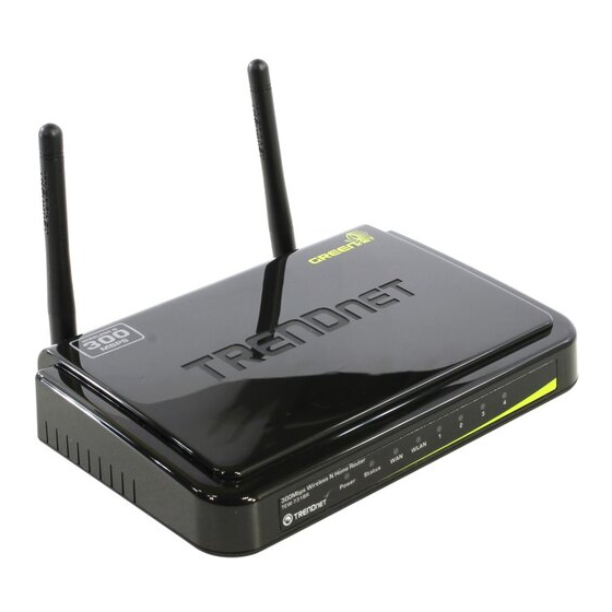
300mbps wireless n home router
Hide thumbs
Also See for TEW-731BR:
- User manual (61 pages) ,
- Quick installation manual (17 pages) ,
- Specifications (3 pages)
Table of Contents
Advertisement
Advertisement
Table of Contents

Related Manuals for TRENDnet TEW-731BR


Summary of Contents for TRENDnet TEW-731BR
- Page 2 Federal Communication Commission Interference Statement This equipment has been tested and found to comply with the limits for a Class B digital device, pursuant to Part 15 of the FCC Rules. These limits are designed to provide reasonable protection against harmful interference in a residential installation.
- Page 3 10 mW EIRP in the frequency range of 2454 – 2483.5 MHz. For detailed information the end-user should contact the national spectrum authority in France. Česky *Czech+ TRENDnet tímto prohlašuje, že tento TEW-731BR je ve shodě se základními požadavky a dalšími příslušnými ustanoveními směrnice 1999/5/ES.
- Page 4 TRENDnet declara que este TEW-731BR está conforme com os requisitos [Portuguese] essenciais e outras disposições da Directiva 1999/5/CE. Slovensko TRENDnet izjavlja, da je ta TEW-731BR v skladu z bistvenimi zahtevami in [Slovenian] ostalimi relevantnimi določili direktive 1999/5/ES. Slovensky TRENDnet týmto vyhlasuje, že TEW-731BR spĺňa základné požiadavky a všetky [Slovak] príslušné...
- Page 5 Industry Canada Statement: This device complies with RSS-210 of the Industry Canada Rules. Operation is subject to the following two conditions: (1) This device may not cause harmful interference, and (2) this device must accept any interference received, including interference that may cause undesired operation. IMPORTANT NOTE: Radiation Exposure Statement: This equipment complies with Canada radiation exposure limits set forth for an uncontrolled environment.
-
Page 6: Table Of Contents
TABLE OF CONTENTS ..................1 BOUT UIDE Purpose ........................... 1 Terms/Usage ........................... 1 Overview of this User’s Guide ....................1 ................... 2 NTRODUCTION Applications: ........................... 2 Supported Features: ........................ 3 Wireless Performance Considerations ..................4 ................5 NPACKING AND ETUP Unpacking .......................... - Page 7 Time ................................42 Dynamic DNS ..............................43 Wireless ..........................44 Basic................................44 Security ................................46 Advanced ............................... 50 Wi-Fi Protected Setup ............................ 51 Status ............................ 52 Device Information ............................52 Log ................................. 54 Log Setting ..............................55 Statistic................................57 Wireless ................................. 57 Routing ..........................
-
Page 8: About This Guide
This manual discusses how to install the TEW-731BR 300Mbps Wireless N Home Router. Terms/Usage In this guide, the term “the WLAN Router” refers to your TEW-731BR 300Mbps Wireless N Home Router. Overview of this User’s Guide Introduction. Describes the TEW-731BR 300Mbps Wireless N Home Router and its features. -
Page 9: Introduction
INTRODUCTION With the explosive growth of the Internet, accessing information and services at any time, day or night has become a standard requirement for most people. The era of the standalone PC is waning. Networking technology is moving out of the exclusive domain of corporations and into homes with at least two computers. -
Page 10: Supported Features
Supported Features: Wi-Fi compliant with IEEE 802.11n and IEEE 802.11b/g standards 4 x 10/100Mbps Auto-MDIX LAN port and 1 x 10/100Mbps WAN port (Internet) Supports Cable/DSL modems with Dynamic IP, Static IP, PPPoE, PPTP, L2TP connection types High-speed data rates up to 300Mbps using an IEEE 802.11n connection ... -
Page 11: Wireless Performance Considerations
Wireless Performance Considerations There are a number of factors that can impact the range of wireless devices. 1. Adjust your wireless devices so that the signal is traveling in a straight path, rather than at an angle. The more material the signal has to pass through the more signal you will lose. -
Page 12: Unpacking And Setup
This chapter provides unpacking and setup information for the TEW-731BR 300Mbps Wireless N Home Router. Unpacking Open the box of the TEW-731BR 300Mbps Wireless N Home Router and carefully unpack it. The box should contain the following items: TEW-731BR 300Mbps Wireless N Home Router ... -
Page 13: Hardware Installation
HARDWARE INSTALLATION Front Panel The figure below shows the front panel of the TEW-731BR 300Mbps Wireless N Home Router. Front Panel POWER This indicator lights green when the hub is receives power, otherwise it is off. Status This indicator blinking green means the WLAN Router is working successfully. -
Page 14: Rear Panel
Rear Panel The figure below shows the rear panel of the TEW-731BR 300Mbps Wireless N Home Router. Rear Panel Antennas There are two 2dBi gain antenna on the rear panel for wireless connection. LAN (1-4) Four RJ-45 10/100Mbps Auto-MDIX ports for connecting to either 10Mbps or 100Mbps Ethernet connections. -
Page 15: Side Panel
Side Panel The figure below shows the side panel of the TEW-731BR 300Mbps Wireless N Home Router. Side Panel Push and hold this button for 3 seconds and release it to initiate the Wi-Fi Protected Setup process. Hanging Way User can mount the device on a wall. -
Page 16: Hardware Connections
Hardware connections Connecting the WLAN Router 1. Plug in one end of the network cable to the WAN port of the WLAN Router. 2. Plug in the other end of the network cable to the Ethernet port of the xDSL or Cable modem. -
Page 17: Check The Installation
Check the installation The control LEDs of the WLAN Router are clearly visible and the status of the network link can be seen instantly: 1. With the power source on, once the device is connected to the broadband modem, the Power, Status, LAN, WLAN and WAN port LEDs of the WLAN Router will light up indicating a normal status. -
Page 18: Pc Network Tcp/Ip Settings
PC NETWORK TCP/IP SETTINGS The network TCP/IP settings differ based on the computer’s operating system (Win95/98/ME/NT/2000/XP/Vista) and are as follows. Windows 95/98/ME 1. Click on the “Network neighborhood” icon found on the desktop. 2. Click the right mouse button and a context menu will be show. 3. -
Page 19: Windows 2000
6. Select “None” for the “Gateway address” field. Windows 2000 Double click on the “My Computer” icon on the desktop. When “My Computer” window opens, select “Control Panel” and then open the “Network dialup connection” applet. Double click on the “Local area network connection” icon. Select “Properties”... -
Page 20: Windows Xp
Windows XP Point the cursor and click the right button on the “My Network Place” icon. Select “properties” to enter the TCP/IP setting window. 1. Click “Start” button, and click on “Control Panel”. 2. Click on “Network and Internet Connections” and click on “Network Connections”. - Page 21 4. Click on “Internet Protocol (TCP/IP)” and click on “Properties”. 5. Set “IP address” to “Obtain an IP address automatically.” 6. Set “DNS” to “Obtain DNS server address automatically.”...
-
Page 22: Windows Vista / 7
Windows Vista / 7 1. Click on the “Start/Windows” button. Right click on “Network” and select “Properties”. 2. Window Vista: Click on “Manage Network Connections. Windows 7: Click on “Change adapter settings”. 3. Right click “Local Area Connection” and select “Properties”. Click on “Internet Protocol Version 4 (TCP/IPv4)”... - Page 23 4. Set “IP address” to “Obtain an IP address automatically.” 5. Set “DNS” to “Obtain DNS server address automatically.”...
-
Page 24: Configuration
CONFIGURATION First make sure that the network connections are functioning normally. This WLAN Router can be configured using Internet Explorer 6.0 or newer web browser versions. Login to the WLAN Router through Wireless LAN Before configuring the WLAN Router through WLAN, make sure that the SSID, Channel and the WEP is set properly. -
Page 25: Using The Web Browser
Using the Web Browser 1. Open Internet Explorer 6.0 or above Internet browser. 2. Enter IP address http://192.168.10.1 (the factory-default IP address setting) to the URL web address location. 3. When the following dialog box appears, enter the user name and password to login to the main configuration window, the default username and password is “admin”. -
Page 26: Setup Wizard
Setup Wizard Setup wizard is provided as part of the web configuration utility. User can simply follow the step-by-step process to get the wireless Router configuration ready to run in 6 easy steps by clicking on` the “Wizard” button on the function menu. The following screen will appear. - Page 27 Step 3: Set LAN connection and DHCP server Set user’s IP address and mask. The default IP is 192.168.10.1. If the user chooses to enable DHCP, please click “Enable”. DHCP enabled is able to automatically assign IP addresses. Please assign the range of IP addresses in the fields of “Range start”...
- Page 28 Step 4: Set Internet connection The WLAN Router will attempt to auto detect your Internet Connection. Obtain IP automatically (DHCP client): If the user has enabled DHCP server, choose "Obtain IP automatically (DHCP client)" to have the WLAN Router assign IP addresses automatically.
- Page 29 Fixed IP Address: If the Internet Service Provider (ISP) assigns a fixed IP address, choose this option and enter the assigned WAN IP Address, WAN Subnet Mask, WAN Gateway Address and DNS Server Addresses for the WLAN Router.
- Page 30 PPPoE to obtain IP automatically: If connecting to the Internet using a PPPoE (Dial-up xDSL) connection, and the ISP provides a User Name and Password, then choose this option and enter the required information.
- Page 31 PPPoE with a fixed IP address: If connecting to the Internet using a PPPoE (Dial-up xDSL) connection and the ISP provides a User Name, Password and a Fixed IP Address, choose this option and enter the required information.
- Page 32 PPTP: If connecting to the Internet using a PPTP (Dial-up xDSL) connection, enter your IP, Subnet Mask, Gateway, Server IP, PPTP Account and PPTP Password.
- Page 33 L2TP: If connecting to the Internet using a L2TP (Dial-up xDSL) connection and the ISP provides a Server IP, Account and Password information, choose this option and enter the required information.
- Page 34 Russia PPPoE (Russia): If connecting to the Internet using a Russia PPPoE connection, the ISP will provide a User Name, Password, and a Fixed or Dynamic IP address. Choose this option and enter the required information.
- Page 35 Russia PPTP (Russia): If connecting to the Internet using a Russia PPTP connection, the ISP will provide either a Fixed or Dynamic IP, Subnet Mask, Gateway, Server IP, PPTP Account and PPTP Password. Choose this option and enter the required information.
- Page 36 Russia L2TP (Russia): If connecting to the Internet using a Russia L2TP connection, the ISP will provide either a Fixed or Dynamic IP, Subnet Mask, Gateway, Server IP, L2TP Account and L2TP Password. Choose this option and enter the required information.
- Page 37 Step 5: Set Wireless LAN connection Click “Enable” to enable Wireless LAN. If user enables the Wireless LAN, type the SSID in the text box and select a communications channel. The SSID and channel must be the same as wireless devices attempting to connect to the WLAN Router. Step 6: Setup completed The Setup wizard is now completed.
-
Page 38: Advanced Configuration
Advanced configuration Main The screen enables users to configure the LAN & DHCP Server, set WAN parameters, create Administrator and User passwords, and set the local time, time zone, and dynamic DNS. LAN & DHCP Server This page allows the user to configure LAN and DHCP properties, such as the host name, IP address, subnet mask, and domain name. - Page 39 Host Name: Type the host name in the text box. The host name is required by some ISPs. The default host name is "TEW-731BR". IP Address: This is the IP address of the WLAN Router. The default IP address is 192.168.10.1.
-
Page 40: Wan
This screen enables users to set up the WLAN Router WAN connection, specify the IP address for the WAN, add DNS numbers, and enter the MAC address. Connection Type: Select the connection type, either DHCP client, Fixed IP, PPPoE, PPTP, L2TP, or Russia PPPoE/PPTP/L2TP from the drop-down list. WAN IP: Select whether user wants to specify an IP address manually, or want DHCP to obtain an IP address automatically. - Page 41 DHCP Client or Fixed IP If user has enabled DHCP server, choose "Obtain IP automatically (DHCP client)" to have the router assign IP addresses automatically. WAN IP Address: Select whether user wants to specify an IP address manually, or want DHCP to obtain an IP address automatically. When Specify IP is selected, type the IP address, subnet mask, and default gateway in the text boxes.
- Page 42 PPPoE If connected to the Internet using a PPPoE (Dial-up xDSL) Modem, the ISP will provide a Password and User Name, and then the ISP uses PPPoE. Choose this option and enter the required information. WAN IP: Select the WAN IP address Obtain from ISP automatically or enter the specified IP address.
- Page 43 PPTP/L2TP with Dynamic IP If connected to the Internet using a PPTP/L2TP (Dial-up xDSL) with dynamic IP connection, enter the your Server IP, PPTP/L2TP Account and PPTP/L2TP Password, if your ISP has provided you with a DNS IP address, enter it in the DNS field, otherwise, leave it zero.
- Page 44 PPTP/L2TP with Static IP If connected to the Internet using a PPTP/L2TP (Dial-up xDSL) with static IP connection, enter the your IP Address, Subnet Mask, Gateway IP address, DNS IP address, Server IP address, PPTP Account and PPTP Password.
- Page 45 Russia PPPoE (Russia): If connecting to the Internet using a Russia PPPoE connection, the ISP will provide a User Name, Password, and a Fixed or Dynamic IP address and the WAN physical setting. Choose this option and enter the required information.
- Page 46 Russia PPTP (Russia): If connecting to the Internet using a Russia PPTP connection, the ISP will provide either a Fixed or Dynamic IP, Subnet Mask, Gateway, Server IP, PPTP Account and PPTP Password. Choose this option and enter the required information.
- Page 47 Russia L2TP (Russia): If connecting to the Internet using a Russia L2TP connection, the ISP will provide either a Fixed or Dynamic IP, Subnet Mask, Gateway, Server IP, L2TP Account and L2TP Password. Choose this option and enter the required information.
-
Page 48: Password
Password This screen enables users to set administrative and user passwords. These passwords are used to gain access to the WLAN Router interface. Administrator: Type the password the Administrator will use to log into the system. The password must be typed again for confirmation. The Administrator can also authorize users the ability to configure the WLAN Router. -
Page 49: Time
Time This screen enables users to set the time and date for the WLAN Router's real-time clock, select properly time zone, and enable or disable daylight saving. Local Time: Displays the local time and date. Time Zone: Select the time zone from the drop-down list. Synchronize the clock with: Select the clock adjustment method form the drop- down list. -
Page 50: Dynamic Dns
Dynamic DNS This synchronizes the DDNS server with your current Public IP address when you are online. First, you need to register your preferred DNS with the DDNS provider. Then, please select the DDNS address in the Server Address and fill the related information in the below fields: Host Name, User Name and Password. -
Page 51: Wireless
Wireless This section enables users to configuration the wireless communications parameters for the WLAN Router. Basic This page allow user to enable and disable the wireless LAN function, create a SSID, and select the channel for wireless communications. Enable/Disable: Enables or disables wireless LAN via the WLAN Router. SSID: Type an SSID in the text box. - Page 52 Channel Width: Select the Channel Width: 20MHz – This is the default setting. Select this option if you are not using any 802.11n wireless clients. Auto 20/40 MHz - Select this option if you are using both 802.11n and non- 802.11n wireless devices.
-
Page 53: Security
Security Authentication Type: The authentication type default is set to open system. There are four options: Disabled, WEP, WPA, WPA2 and WPA-Auto. WEP Encryption WEP: Open System and Shared Key requires the user to set a WEP key to exchange data with other wireless clients that have the same WEP key. Mode: Select the key type: ASCII or HEX WEP Key: Select the level of encryption from the drop-down list. - Page 54 Key Length ASCII Type characters 0-9, A-F, a-f alphanumeric format 64-bit 10 characters 5 characters 128-bit 26 characters 13 characters Key 1: Enables users to create WEP keys with WPS enabled. Manually enter a set of values for Key 1. Key 1 ~ Key 4: Enables users to create up to 4 different WEP keys with WPS disabled.
- Page 55 WPA/WPA2/WPA-Auto Security with EAP If WPA, WPA2 or WPA-Auto EAP is selected, the above screen is shown. Please set the length of the encryption key and the parameters for the RADIUS server. Cipher Type: Select the cipher type for TKIP or AES encryption, Selected Auto for auto detects the cipher type.
- Page 56 WPA/WPA2/WPA-Auto Security with PSK If WPA, WPA2 or WPA-Auto PSK is selected, the above screen is shown. Please set the length of the encryption key. Cipher Type: Select the cipher type for TKIP or AES encryption, Selected Auto for auto detects the cipher type. Passphrase: The length should be 8 characters at least.
-
Page 57: Advanced
Advanced This screen enables users to configure advanced wireless functions. Beacon Interval: Type the beacon interval in the text box. User can specify a value from 25 to 1000. The default beacon interval is 100. RTS Threshold: Type the RTS (Request-To-Send) threshold in the text box. This value stabilizes data flow. -
Page 58: Wi-Fi Protected Setup
Wi-Fi Protected Setup This screen enables users to configure the Wi-Fi Protected Setup function. WPS: Enable or Disable the WPS (Wi-Fi Protected Setup) function Status: Display the status (Un-configured State/Configured State) information of WPS. Self-PIN Number: Display the current PIN number of the WLAN Router. Client PIN Number: Type Client’s PIN number the client uses to negotiate with the WLAN Router via WPS connection. -
Page 59: Status
Status This selection enables users to view the status of the WLAN Router LAN, WAN and Wireless connections, and view logs and statistics pertaining to connections and packet transfers. Device Information This screen enables users to view the WLAN Router’s LAN, Wireless and WAN configurations. - Page 60 Firmware Version: Displays the latest build of the WLAN Router firmware interface. After updating the firmware in Tools - Firmware, check this to ensure that the firmware was successfully updated. WAN: This section displays the WAN interface configuration including the MAC address, Connection status, DHCP client status, IP address, Subnet mask, Default gateway, and DNS.
-
Page 61: Log
This screen enables users to view a running log of Router system statistics, events, and activities. The log displays up to 200 entries. Older entries are overwritten by new entries. The Log screen commands are as follows: Click “First Page” to view the first page of the log Click “Last Page”... -
Page 62: Log Setting
Log Setting This screen enables users to set Router Log parameters. SMTP Authentication: Selected the Enabled if the SMTP server need for authentication, fill in account name and password in SMTP Account field and SMTP Password field. SMTP Account: If the SMTP Authentication enabled, fill in the SMTP account name here. - Page 63 E-mail Logs: Email the logs to specified email receiver. When log is full - The time is not fixed. The log will be sent when the log is full, which will depend on the volume of traffic. Every day, Every Monday ... - The log is sent on the interval specified. ...
-
Page 64: Statistic
Statistic This screen displays a table that shows the rate of packet transmission via the WLAN Router’s LAN, Wireless and WAN ports (in bytes per second). Wireless This screen enables users to view information about wireless devices that are connected to the WLAN Router. Connected Time: Displays the time duration of wireless clients connection to the WLAN Router. -
Page 65: Routing
Routing This selection enables users to set how the WLAN Router forwards data: Static and Dynamic. Routing Table enables users to view the information created by the WLAN Router that displays the network interconnection topology. Static It enables users to create static routes to other IP networks through next hop routers. -
Page 66: Dynamic
Dynamic It enables users to enable RIPv1 or RIPv2 (Routing Information Protocol) on all of the router interfaces, to transmit and/or receive RIP information to and from other routers also using the RIP protocol. This allows the router to dynamically learn routes and exchange route information of other IP networks between other RIP routers. -
Page 67: Routing Table
Routing Table This screen enables users to view the routing table of the WLAN Router. The routing table is a database created by the WLAN Router that displays the network interconnection topology. Network Address: Displays the destination network IP address. Network Mask: Displays the destination network subnet mask. -
Page 68: Access
Access This page enables you to define access restrictions, set up protocol and IP filters, create virtual servers, define access for special applications such as games, and set firewall rules. Filters Using filters to deny or allow the users to access to the internet. Three types of filters can be select: MAC, Domain/URL blocking, and Protocol/IP filter. - Page 69 MAC Filters MAC Filter: Enables you to allow or deny computers or devices access to the router, access to your wired/wireless local network, and accessing the Internet. Disable: Disable the MAC filter function. Allow: Only allow computers with MAC address listed in the MAC Table. Deny: Computers in the MAC Table are denied access to the router, access to your wired/wireless local network (LAN/WLAN), and Internet access.
- Page 70 Name: Type the name of the user to be permitted/denied access. MAC Address: Type the MAC address of the user's network interface. Add: Click to add the user to the list at the bottom of the page. Update: Click to update information for the user, if you have changed any of the fields.
- Page 71 Domain/URL Blocking You could specify the domains that allow users to access or deny by clicking one of the two items. Also, add the specified domains in the text box. Disable: Disable the Domain/URL Blocking function. Allow: Allow users to access all domains except “Domains List”. ...
- Page 72 Protocol/IP Filters This screen enables you to define a minimum and maximum IP address range filter; all IP addresses falling within the range are not allowed accessing internet. The IP filter profiles are listed in the table at the bottom of the page. (Note: Click anywhere in the item.
- Page 73 Port: Type the port range of the protocol. IP Range: Type the IP range. IP addresses falling between this value and the Range End are not allowed to access the Internet. Add: Click to add the IP range to the table at the bottom of the screen. ...
-
Page 74: Virtual Server
Virtual Server This screen enables user to create a virtual server via the WLAN Router. If the WLAN Router is set as a virtual server, remote users requesting Web or FTP services through the WAN are directed to local servers in the LAN. The WLAN Router redirects the request via the protocol and port numbers to the correct LAN server. - Page 75 Enable: Click to enable or disable the virtual server. Name: Type a descriptive name for the virtual server. Protocol: Select a protocol (TCP or UDP) to use for the virtual server. Private Port: Type the port number of the computer on the LAN that is being used to act as a virtual server.
-
Page 76: Special Ap
Special AP This screen enables users to specify special applications, such as games which require multiple connections that are blocked by NAT. The special applications profiles are listed in the table at the bottom of the page. Note: When selecting items in the table at the bottom, click anywhere in the item. The line is selected, and the fields automatically load the item's parameters, which user can edit. -
Page 77: Dmz
Port Range: Type the port range that can be used to access the application in the text boxes. Incoming: Defines which incoming communications users are permitted to connect with. Protocol: Select the protocol (TCP, UDP, or * for TCP+UDP) that can be used by the incoming communication. -
Page 78: Firewall Settings
Firewall Settings This screen enables users to set up the firewall. The WLAN Router provides basic firewall functions, by filtering all the packets that enter the WLAN Router using a set of rules. The rules are listed in sequential order--the lower the rule number, the higher the priority the rule has. - Page 79 ● IP Range End: Type the end IP address that the rule is applied to. ● Protocol: Select the protocol (TCP, UDP, or ICMP) of the destination. ● Port Range: Select the port range. Add: Click to add the rule profile to the table at the bottom of the screen. Update: Click to update information for the rule if the user has selected a listed item and has made changes.
-
Page 80: Management
Management Management enables users to set up the SNMP and Remote Management features. SNMP (Simple Network Management Protocol) This screen allows you to enable and configure SNMP (Simple Network Management Protocol) on the router. Using SNMP, notification messages or SNMP Traps (router status/device information) can be sent from the router to external SNMP management stations/Trap Receivers for device monitoring purposes. -
Page 81: Remote Management
Remote Management This screen enables users to set up remote management. Using remote management, the WLAN Router can be configured through the WAN via a Web browser. A user name and password are required to perform remote management. HTTP: Enables users to set up HTTP access of the Port number, and Remote IP Range for remote management. -
Page 82: Capture Packets
Capture Packets This screen allows you to capture packets on the LAN and/or WAN interfaces of the WLAN router for further analysis and troubleshooting. Packet captures allow you to see the detailed data and information inside data packets. You will need a third party packet capture application in order to open and view the packet capture files download from the router. -
Page 83: Tools
Tools This page enables users to restart the system, save and load different settings as profiles, restore factory default settings, run a setup wizard to configure WLAN Router settings, upgrade the firmware, and ping remote IP addresses. Restart Click “Restart” to restart the system in the event the system is not performing correctly. -
Page 84: Firmware
Firmware This screen enables users to keep the WLAN Router firmware up to date. Please follow the below instructions: Download the latest firmware from the manufacturer's Web site, and save it to disk. Click “Browse” and go to the location of the downloaded firmware file. Select the file and click “Upgrade”... -
Page 85: Technical Specifications
TECHNICAL SPECIFICATIONS Hardware Standards IEEE 802.3 (10BASE-T), IEEE 802.3u (100BASE-TX), IEEE 802.11b/g/n, IEEE 802.3az 1 x 10/100Mbps Auto-MDIX port (Internet) 4 x 10/100Mbps Auto-MDIX ports WPS Button Enables Wi-Fi Protected Setup (WPS) function Connection Type Dynamic IP, Static (Fixed) IP, PPPoE, PPTP, L2TP UPnP UPnP IGD 1.0 compliant DMZ host &... -
Page 86: Limited Warranty
Upon proper submission of required documentation a Return Material Authorization (RMA) number will be issued. An RMA number is required in order to initiate warranty service support for all TRENDnet products. Products that are sent to TRENDnet for RMA service must have the RMA number marked on the outside of return packages and sent to TRENDnet prepaid, insured and packaged appropriately for safe shipment. - Page 87 Some TRENDnet products include software code written by third party developers. These codes are subject to the GNU General Public License ("GPL") or GNU Lesser General Public License ("LGPL"). Go to http://www.trendnet.com/gpl http://www.trendnet.com Download section and look for the desired TRENDnet product to access to the GPL Code or LGPL Code.
Need help?
Do you have a question about the TEW-731BR and is the answer not in the manual?
Questions and answers