
Subscribe to Our Youtube Channel
Related Manuals for Dell EMC XC940 XC Series


Summary of Contents for Dell EMC XC940 XC Series
- Page 1 Dell EMC XC940 XC Series Appliance and XC Core System Installation and Service Manual Regulatory Model: E41S Series Regulatory Type: E41S001...
- Page 2 A WARNING indicates a potential for property damage, personal injury, or death. © 2018 Dell Inc. or its subsidiaries. All rights reserved. Dell, EMC, and other trademarks are trademarks of Dell Inc. or its subsidiaries. Other trademarks may be trademarks of their respective owners.
-
Page 3: Table Of Contents
Contents 1 Dell EMC XC940 XC Series Appliance and XC Core System overview............7 Front view of the system..............................7 Left control panel view..............................9 Right control panel..............................12 Back view of the system..............................13 NIC indicator codes..............................14 Power supply unit indicator codes..........................15 Drive indicator codes................................ - Page 4 System Setup................................... 32 Viewing System Setup.............................. 32 System Setup details..............................33 System BIOS................................33 iDRAC Settings utility..............................52 Device Settings................................52 Dell Lifecycle Controller..............................52 Embedded systems management..........................52 Boot Manager...................................52 Viewing Boot Manager..............................53 Boot Manager main menu............................53 One-shot BIOS boot menu............................53 System Utilities................................53...
- Page 5 Entering the system Service Tag by using System Setup...................104 Trusted Platform Module...............................105 Upgrading the Trusted Platform Module.......................105 Initializing the TPM 1.2 for TXT users........................106 Initializing the TPM 2.0 for TXT users........................106 7 Using system diagnostics..........................107 Dell Embedded System Diagnostics..........................107 Contents...
- Page 6 Running the Embedded System Diagnostics from Boot Manager..............107 Running the Embedded System Diagnostics from the Dell Lifecycle Controller..........107 System diagnostic controls............................. 108 8 Jumpers and connectors ........................... 109 System board connectors.............................. 110 System board jumper settings............................113 Disabling forgotten password............................113 9 Getting help..............................
-
Page 7: Dell Emc Xc940 Xc Series Appliance And Xc Core System Overview
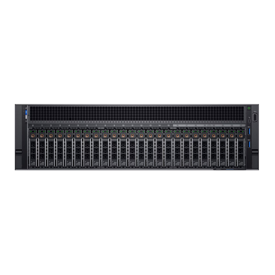
Sections or information that apply to only one of the offerings (XC Series or XC Core) will be called out explicitly. The Dell EMC XC940 XC Series Appliance and XC Core system is a 3U rack system, which is available in the following configuration: Table 1. - Page 8 Service Tag, NIC, MAC address, and so on. If you have opted for secure default access to iDRAC, the Information tag also contains the iDRAC secure default password. Dell EMC XC940 XC Series Appliance and XC Core System overview...
-
Page 9: Left Control Panel View
Check the System Event Log to determine if the drive there is a drive error. has an error. • Run the appropriate Online Diagnostics test. Restart the system and run embedded diagnostics (ePSA). Dell EMC XC940 XC Series Appliance and XC Core System overview... -
Page 10: System Health And System Id Indicator Codes
ID mode. Blinking blue Indicates that the system ID mode is active. Press the system health and system ID button to switch to system health mode. Dell EMC XC940 XC Series Appliance and XC Core System overview... -
Page 11: Idrac Quick Sync 2 Indicator Codes
Restart the system. If the problem persists, see mode. Getting help. Blinking amber Indicates that the iDRAC Quick Sync 2 Restart the system. If the problem persists, see feature is not responding properly. Getting help. Dell EMC XC940 XC Series Appliance and XC Core System overview... -
Page 12: Right Control Panel
You can configure iDRAC Direct by using a USB to micro USB (type AB) cable, which you can connect to your laptop or tablet. The following table describes iDRAC Direct activity when the iDRAC Direct port is active: Dell EMC XC940 XC Series Appliance and XC Core System overview... -
Page 13: Back View Of The System
The expansion card riser (left) supports up to three full-height PCI expansion card riser (left) Express expansion cards. For more information, see Expansion card installation guidelines. Power supply unit (2) For more information, see Technical specifications. Dell EMC XC940 XC Series Appliance and XC Core System overview... -
Page 14: Nic Indicator Codes
The NIC is connected to a valid network at less than its maximum port speed and data is not being sent or received. Link indicator is blinking green and activity is off NIC identify is enabled through the NIC configuration utility. Dell EMC XC940 XC Series Appliance and XC Core System overview... -
Page 15: Power Supply Unit Indicator Codes
If two PSUs are used, they must be of the same type and have the same maximum output power. CAUTION: Combining AC and DC PSUs is not supported and triggers a mismatch. Dell EMC XC940 XC Series Appliance and XC Core System overview... - Page 16 If two PSUs are used, they must be of the same type and have the same maximum output power. CAUTION: Combining AC and DC PSUs is not supported and triggers a mismatch. Dell EMC XC940 XC Series Appliance and XC Core System overview...
-
Page 17: Drive Indicator Codes
Drive failed. Flashes green slowly Drive rebuilding. Solid green Drive online. Flashes green for three seconds, amber for three seconds, and Rebuild stopped. then turns off after six seconds Dell EMC XC940 XC Series Appliance and XC Core System overview... -
Page 18: Locating The Service Tag Of Your System
Express Service Code and Service Tag. Alternatively, the information may be on a sticker on the chassis of the system. The mini Enterprise Service Tag (EST) is found on the back of the system. This information is used by Dell EMC to route support calls to the appropriate personnel. -
Page 19: Documentation Resources
Dell EMC documentation for Dell EMC iDRAC is available at Dell.com/idracmanuals. To access the Dell EMC documentation: On the Dell EMC Support page, in the Enter a Service Tag, Serial Number, Service Request, Model, or Keyword box, type the Service Tag of your Dell EMC appliance, and then click Submit. -
Page 20: Technical Specifications
Technical specifications The technical and environmental specifications of your system are outlined in this section. Topics: • System dimensions • System weight • Processor specifications • PSU specifications • System battery specifications • Expansion bus specifications • Memory specifications • Storage controller specifications •... -
Page 21: System Weight
Figure 12. System dimensions of XC940 Series system Table 15. System dimensions of XC940 Series system system Za (with Za (without bezel) bezel) XC940 Series system 482.0 mm 434.0 mm 130.3 mm 35.0 mm 22.0 mm 726.2 mm 777.046 mm (18.9 inches) (17.08 (5.13... -
Page 22: Psu Specifications
PSU specifications The XC940 Series system supports up to two AC or DC power supply units (PSUs). Table 17. PSU specifications Class Heat dissipation Frequency Voltage Power rating Current (maximum) 1100 W AC Platinum 4100 BTU/hr 50/60 Hz 100–120 V AC, autoranging derated to 1050 W 12 A–6.5 200–240 V AC, 1100 W... -
Page 23: Memory Specifications
Table 18. Expansion card slots supported on the system board PCIe slot on the system Processor PCIe slots on system PCIe slots on Link width Slot width board connection board (Height) system board (length) Slot 1 Processor 1 full height half length Slot 2 Processor 1... -
Page 24: Remote Management Port Specifications
Remote management port specifications The XC940 Series system supports one dedicated 1Gbe Ethernet port with optional card and up to two optional shared NIC ports. Drive specifications Hard drives The XC940 Series system supports up to twenty four 2.5-inch, internal, hot swappable SAS or SATA SSDs/hard drives. Ports and connectors specifications USB ports The XC940 Series system supports:... -
Page 25: Video Specifications
1680 x 1050 60 (RB) 1920 x 1080 1920 x 1200 Environmental specifications NOTE: For additional information about environmental measurements for specific system configurations, see Dell.com/ environmental_datasheets. Table 22. Temperature specifications Temperature Specifications Storage –40°C to 65°C (–40°F to 149°F) Continuous operation (for altitude less than 950 m or 3117 10°C to 35°C (50°F to 95°F) with no direct sunlight on the equipment. -
Page 26: Particulate And Gaseous Contamination Specifications
Table 25. Maximum shock specifications Maximum shock Specifications Operating Six consecutively executed shock pulses in the positive and negative x, y, and z axes of 6 G for up to 11 ms. Storage Six consecutively executed shock pulses in the positive and negative x, y, and z axes (one pulse on each side of the system) of 71 G for up to 2 ms. -
Page 27: Standard Operating Temperature
Particulate contamination Specifications Corrosive dust • Air must be free of corrosive dust. • Residual dust present in the air must have a deliquescent point less than 60% relative humidity. NOTE: This condition applies to data center and non-data center environments. -
Page 28: Expanded Operating Temperature Restrictions
150 W/8 core or higher wattage processor [Thermal Design Power (TDP)>165 W] is not supported. • Redundant power supply unit is required. • Non-Dell EMC qualified peripheral cards and/or peripheral cards greater than 25 W are not supported. • NVMe drives are not supported. Thermal restrictions The following table lists the configuration required for efficient cooling: Table 32. -
Page 29: Initial System Setup And Configuration
Complete the following steps to set up your system: Unpack the system. Install the system into the rack. For more information about installing the system into the rack, see Rail Installation Guide at Dell.com/ XCSeriesmanuals. Connect the peripherals to the system. -
Page 30: Log In To Idrac
Ensure that you change the default user name and password after setting up the iDRAC IP address. For more information about logging in to the iDRAC and iDRAC licenses, see the latest Integrated Dell Remote Access Controller User's Guide at Dell.com/idracmanuals. - Page 31 Download the drivers to a USB drive, CD, or DVD. Initial system setup and configuration...
-
Page 32: Pre-Operating System Management Applications
Pre-operating system management applications Dell EMC recommends that you do not change any of the factory settings. XC Series Appliance and XC Core System settings are configured at the factory. Topics: • Options to manage the pre-operating system applications •... -
Page 33: System Setup Details
The iDRAC settings utility is an interface to set up and configure the iDRAC parameters by using UEFI (Unified Extensible Firmware Interface). You can enable or disable various iDRAC parameters by using the iDRAC settings utility. For more information about this utility, see Integrated Dell Remote Access Controller User’s Guide at Dell.com/idracmanuals. -
Page 34: Viewing System Information
Option Description NVMe Settings Specifies options to change the NVMe settings. If the system contains the NVMe drives that you want to configure in a RAID array, you must set this field and the Embedded SATA field on the SATA Settings menu to RAID mode. -
Page 35: Memory Settings
Option Description System BIOS Specifies the BIOS version installed on the system. Version System Specifies the current version of the Management Engine firmware. Management Engine Version System Service Tag Specifies the system Service Tag. System Specifies the name of the system manufacturer. Manufacturer System Specifies the contact information of the system manufacturer. -
Page 36: Processor Settings
Specifies the memory operating mode. The options available are Optimizer Mode, Single Rank Spare Mode, Multi Mode Rank Spare Mode, Mirror Mode, and Dell Fault Resilient Mode. This option is set to Optimizer Mode by default. NOTE: The Memory Operating Mode option can have different default and available options based on the memory configuration of your system. - Page 37 Disabled by default. X2APIC Mode Enables or disables the X2APIC mode. This option is set to Disabled by default. Dell Controlled Controls the turbo engagement. Enable this option only when System Profile is set to Disabled. Turbo Number of Cores Controls the number of enabled cores in each processor.
- Page 38 Option Description Option Description Family-Model- Specifies the family, model, and stepping of the processor as defined by Intel. Stepping Brand Specifies the brand name. Level 2 Cache Specifies the total L2 cache. Level 3 Cache Specifies the total L3 cache. Number of Cores Specifies the number of cores per processor.
- Page 39 Option Description Option Description Drive Type Specifies the type of drive attached to the SATA port. Capacity Specifies the total capacity of the hard drive. This field is undefined for removable media devices such as optical drives. Port B Sets the drive type of the selected device. For the Embedded SATA settings in ATA mode, set this field to Auto to enable BIOS support.
-
Page 40: Boot Settings
Viewing NVMe Settings To view the NVMe Settings screen, perform the following steps: Turn on, or restart your system. Press F2 immediately after you see the following message: F2 = System Setup NOTE: If your operating system begins to load before you press F2, wait for the system to finish booting, and then restart your system and try again. -
Page 41: Integrated Devices
Boot Settings details NOTE: The NVDIMM-N, RAID or UEFI settings are not supported. The Boot Settings screen details are explained as follows: Option Description Boot Mode Enables you to set the boot mode of the system. CAUTION: Switching the boot mode may prevent the system from booting if the operating system is not installed in the same boot mode. - Page 42 Steps Turn on, or restart your system. Press F2 immediately after you see the following message: F2 = System Setup NOTE: If your operating system begins to load before you press F2, wait for the system to finish booting, and then restart your system and try again.
- Page 43 Option Description Internal SD Primary When Redundancy is set to Disabled, either one of the SD card can be selected to present itself as mass storage Card device by setting it to be primary card. By default primary SD card is selected to be SD Card 1. If microSD Card 1 is not present, then the controller selects the SD Card 2 as the primary card.
-
Page 44: Serial Communication
Serial Communication You can use the Serial Communication screen to view the properties of the serial communication port. Viewing Serial Communication To view the Serial Communication screen, perform the following steps: Turn on, or restart your system. Press F2 immediately after you see the following message: F2 = System Setup NOTE: If your operating system begins to load before you press F2, wait for the system to finish booting, and then restart... - Page 45 You can only change the rest of the options if the mode is set to Custom.This option is set to Performance Per Watt Optimized (DAPC) by default. DAPC is Dell Active Power Controller. Other options include Performance Per Watt (OS), Performance Per Watt (HWPM), Performance, and Workstation Performance.
-
Page 46: System Security
Option Description Dynamic mode enables the processor to optimize power resources across the cores and uncore during runtime. The optimization of the uncore frequency to either save power or optimize performance is influenced by the setting of the Energy Efficiency Policy option. Energy Efficient Enables you to select the Energy Efficient Policy option. - Page 47 Option Description In-Band When set to Disabled, this setting will hide the Management Engine's (ME), HECI devices, and the system's IPMI Manageability devices from the operating system. This prevents the operating system from changing the ME power capping Interface settings, and blocks access to all in-band management tools. All management should be managed through out-of- band.
- Page 48 Option Description Options Description User Mode In User Mode, PK must be installed, and BIOS performs signature verification on programmatic attempts to update policy objects. The BIOS allows unauthenticated programmatic transitions between modes. Audit Mode In Audit mode, PK is not present. The BIOS does not authenticate programmatic updates to the policy objects, and transitions between modes.
-
Page 49: Using Your System Password To Secure Your System
A message prompts you to reenter the setup password. Reenter the setup password, and click OK. Press Esc to return to the System BIOS screen. Press Esc again. A message prompts you to save the changes. NOTE: Password protection does not take effect until the system reboots. Using your system password to secure your system About this task If you have assigned a setup password, the system accepts your setup password as an alternate system password. - Page 50 If you do not type the correct password in three attempts, the system displays the following message: Invalid Password! Number of unsuccessful password attempts: <x> System Halted! Must power down. Password Invalid. Number of unsuccessful password attempts: <x> Maximum number of password attempts exceeded.System halted.
-
Page 51: Miscellaneous Settings
Option Description Redundant OS NOTE: This option is disabled if Redundant OS Location is set to None. State When set to Visible, the backup disk is visible to the boot list and OS. When set to Hidden, the backup disk is disabled and is not visible to the boot list and OS. -
Page 52: Idrac Settings Utility
Dell Lifecycle Controller Dell Lifecycle Controller (LC) provides advanced embedded systems management capabilities including system deployment, configuration, update, maintenance, and diagnosis. LC is delivered as part of the iDRAC out-of-band solution and Dell system embedded Unified Extensible Firmware Interface (UEFI) applications. -
Page 53: Viewing Boot Manager
Launch System Enables you to access System Setup. Setup Launch Lifecycle Exits the Boot Manager and invokes the Dell Lifecycle Controller program. Controller System Utilities Enables you to launch System Utilities menu such as System Diagnostics and UEFI shell. One-shot BIOS boot menu One-shot BIOS boot menu enables you to select a boot device to boot from. - Page 54 To access the PXE boot option, boot the system and then press F12 during POST instead of using standard Boot Sequence from BIOS Setup. It does not pull any menu or allow managing of network devices. Pre-operating system management applications...
-
Page 55: Installing And Removing System Components
Damage due to servicing that is not authorized by Dell is not covered by your warranty. Read and follow the safety instructions that are shipped with your product. -
Page 56: Before Working Inside Your System
Before working inside your system Prerequisite Follow the safety guidelines listed in Safety instructions. Steps Turn off the system, including all attached peripherals. Disconnect the system from the electrical outlet and disconnect the peripherals. Remove the system cover. After working inside your system Prerequisite Follow the safety guidelines listed in Safety... -
Page 57: Installing The Optional Front Bezel
Figure 13. Removing the optional front bezel with the LCD panel Installing the optional front bezel Prerequisite Follow the safety guidelines listed in Safety instructions. Steps Locate and remove the bezel key. NOTE: The bezel key is part of the LCD bezel package. Align and insert the right end of the bezel onto the system. -
Page 58: System Cover
Figure 14. Installing the optional front bezel with the LCD panel System cover System cover provides security for the entire system and also helps in maintaining proper air flow inside the system. Removing the system cover Prerequisites Follow the safety guidelines listed in Safety instructions. -
Page 59: Installing The System Cover
Figure 15. Removing the system cover Installing the system cover Prerequisites Follow the safety guidelines listed in Safety instructions. Ensure that all internal cables are routed correctly and connected, and no tools or extra parts are left inside the system. Steps Align the tabs on the system cover with the guide slots on the system. -
Page 60: Inside The System
Damage due to servicing that is not authorized by Dell is not covered by your warranty. Read and follow the safety instructions that are shipped with your product. -
Page 61: Air Shroud
Figure 17. Inside the system — Four processor system with processor expansion module (PEM) hard drive/SSD backplane with expander board cooling fan (8) air shroud heat sink (CPU3) left expansion card riser storage controller card network daughter card riser system board processor expansion module (PEM) right expansion card riser heat sink (CPU4) -
Page 62: Installing The Air Shroud
Step To remove the air shroud from a four processor configuration system: Remove the expansion card risers. See Removing the expansion card riser. b Hook the expansion card riser on the side of the system by using the I/O riser handle on the expansion card riser. CAUTION: To avoid damage to the PCIe cables connected to the NVMe cards installed in the expansion card riser, ensure that you hook the riser to the system using the I/O riser handle. -
Page 63: Cooling Fans
Figure 19. Installing the air shroud — Four processor system Next step Follow the procedure listed in After working inside your system. Cooling fans The cooling fans are integrated into the system to dissipate the heat generated by the functioning of the system. These fans provide cooling for the processors, expansion cards, and memory modules. -
Page 64: Installing The Cooling Fan
Figure 20. Removing the cooling fan Next step If applicable, install the cooling fan. Installing the cooling fan Prerequisite Follow the safety guidelines listed in Safety instructions. WARNING: Do not drop the fan into the fan cage while removing or installing the fan as this may cause damage to the connectors on the fan tray. -
Page 65: Fan Cage
Figure 21. Installing the cooling fan Next step Install the system cover. Fan cage The sections below contains information about the removal and installation of the fan cage and the fan tray. Removing the fan cage Prerequisites Follow the safety guidelines listed in Safety instructions. -
Page 66: Installing The Fan Cage
Figure 22. Removing the fan cage Next step If applicable, install the fan cage. Installing the fan cage Prerequisite Follow the safety guidelines listed in Safety instructions. Steps Holding the cage handles, lower the cage into the fan tray. Lower the cage handles until the handles lock into place. Installing and removing system components... -
Page 67: Removing The Fan Tray
Figure 23. Installing the fan cage Next step Follow the procedure listed in After working inside your system. Removing the fan tray Prerequisites Follow the safety guidelines listed in Safety instructions. Follow the procedure listed in Before working inside your system. -
Page 68: Installing The Fan Tray
Figure 24. Removing the fan tray Next step If applicable, install the tray. Installing the fan tray Prerequisite Follow the safety guidelines listed in Safety instructions. Steps Holding the fan tray, align the slots on the fan tray with the standoffs on the system. Lower the fan tray into the system until the slots on the fan tray engage with the standoffs on the system. -
Page 69: Intrusion Switch
Figure 25. Installing the fan tray Next steps Route the fan power cables and the backplane cables through the cable clips on the fan tray and connect the cables to the connectors on the system board. If applicable, lower the PEM by using PEM handle until the PEM clicks in place. If removed, install the expansion card risers. -
Page 70: Installing An Intrusion Switch
Press the blue release tabs on the fan tray and lower the sides of the tray. Disconnect the cable connected to the intrusion switch connector (INTRUSION) on the system board. Steps Press the cable management bracket down until the tabs on the bracket disengage from the slots on the side of the system. Lift the cable management bracket out of the system. -
Page 71: Drives
Press the bracket and insert the tabs on the bracket into the slots on the right side of the system. Connect the cable to the connector (INTRUSION) on the system board. Figure 27. Installing an intrusion switch Next steps Lift the sides of the fan tray until the blue release tabs click in place. If applicable, install the expansion card risers. -
Page 72: Removing A Drive Blank
Removing a drive blank Prerequisites Follow the safety guidelines listed in Safety instructions. If installed, remove the front bezel. CAUTION: To maintain proper system cooling, drive blanks must be installed in all empty drive slots. CAUTION: Mixing drive blanks from previous generations of XC Series Appliance and XC Core System is not supported. Step Press the release button, and slide the drive blank out of the drive slot. -
Page 73: Removing A Drive Carrier
Figure 29. Installing a drive blank Next step If removed, install the front bezel. Removing a drive carrier Prerequisites Follow the safety guidelines listed in Safety instructions. If applicable, remove the front bezel. Using the management software, prepare the drive for removal. If the drive is online, the green activity or fault indicator flashes while the drive is turning off. -
Page 74: Installing A Drive Carrier
Figure 30. Removing a drive carrier Next steps Follow the procedure listed in After working inside your system. Install a drive carrier. If you are not replacing the drive immediately, insert a drive blank in the empty drive slot to maintain proper system cooling. Installing a drive carrier Prerequisites CAUTION:... -
Page 75: Removing The Drive From The Drive Carrier
Figure 31. Installing a drive carrier Next step If applicable, install the front bezel. Removing the drive from the drive carrier Prerequisite CAUTION: Mixing drives from previous generations of XC Series Appliance and XC Core System is not supported. Steps Using Phillips #1 screwdriver, remove the screws from the slide rails on the drive carrier. -
Page 76: Installing A Drive Into The Drive Carrier
Figure 32. Removing the drive from the drive carrier Next step If applicable, install the drive into the drive carrier. Installing a drive into the drive carrier Prerequisites CAUTION: Mixing drive carriers from other generations of XC Series Appliance and XC Core System is not supported. NOTE: When installing a drive into the drive carrier, ensure that the screws are torqued to 4 in-lbs. -
Page 77: Hard Drive Backplane
Figure 33. Installing a drive into the drive carrier Hard drive backplane NOTE: NVMe drive slots are 20, 21, 22, and 23. Drive slot numbering is 0 relative for chassis. All NVMe drives are installed in the last slots. Maximum of four NVMe drives are supported. Your system supports 2.5 inch (x24) SAS/SATA backplane. -
Page 78: System Memory
Name State Slot Number Size Security Status Bus Protocol Media Type PCle SSD in Slot Ready 1490.42 GB Not Applicable PCle 22 in Bay 1 PCle SSD in Slot Ready 1490.42 GB Not Applicable PCle 23 in Bay 1 System memory System memory guidelines The system support DDR4 Registered DIMMs (RDIMMs), Load Reduced DIMMs (LRDIMMs), and Non-Volatile DIMMs (NVDIMM-Ns). - Page 79 Figure 35. Memory socket locations Memory channels are organized as follows: Table 38. Memory channels Processor Channel 0 Channel 1 Channel 2 Channel 3 Channel 4 Channel 5 Processor 1 Slots A1 and A7 Slots A2 and A8 Slots A3 and A9 Slots A4 and A10 Slots A5 and A11 Slots A6 and A12...
-
Page 80: General Memory Module Installation Guidelines
General memory module installation guidelines To ensure optimal performance of your system, observe the following general guidelines when configuring your system memory. If your system's memory configurations fail to observe these guidelines, your system might not boot, stop responding during memory configuration, or operate with reduced memory. -
Page 81: Mode-Specific Guidelines
Dell Fault Resilient Mode The Dell Fault Resilient Mode if enabled, the BIOS creates an area of memory that is fault resilient. This mode can be used by an OS that supports the feature to load critical applications or enables the OS kernel to maximize system availability. - Page 82 Optimizer Mode This mode supports Single Device Data Correction (SDDC) only for memory modules that use x4 device width. It does not impose any specific slot population requirements. • Dual processor: Populate the slots in round robin sequence starting with processor 1. NOTE: Processor 1 and processor 2 population should match.
- Page 83 Processor Configuration Memory population Memory population information Optimizer population order is not traditional for 8 and 16 DIMMs installations for dual processor. • For 8 DIMMs: A1, A2, A4, A5, B1, B2, B4, B5 • For 16 DIMMs: A1, A2, A4, A5, A7, A8, A10, A11 B1, B2, B4, B5, B7, B8, B10, B11 Mirroring population order Mirroring is supported with 6 or 12 DIMMs per...
-
Page 84: Removing A Memory Module
Processor Configuration Memory population Memory population information Mirroring population order Mirroring is supported with 6 or 12 DIMM slots per A{1, 2, 3, 4, 5, 6}, processor. B{1, 2, 3, 4, 5, 6}, C{1, 2, 3, 4, 5, 6}, D{1, 2, 3, 4, 5, 6} A{7, 8, 9, 10, 11, 12}, B{7, 8, 9, 10, 11, 12}, C{7, 8, 9, 10, 11, 12},... -
Page 85: Installing A Memory Module
Figure 36. Removing a memory module Next steps Install the memory module. If you are removing the memory module permanently, install a memory module blank. The procedure to install a memory module blank is similar to that of the memory module. Installing a memory module Prerequisite Follow the safety guidelines listed in... -
Page 86: Expansion Cards And Expansion Card Risers
Figure 37. Installing a memory module Next steps Install the air shroud. Follow the procedure listed in After working inside your system. To verify if the memory module has been installed properly, press F2 and navigate to System Setup Main Menu > System BIOS > Memory Settings. -
Page 87: Removing The Expansion Card Riser
Riser PCIe slot on the Processor PCIe slots on riser PCIe slots Link width Slot width expansion card riser connection (Height) on riser (length) Slot 12 Processor 4 full height half length Slot 13 Processor 4 full height half length NOTE: The expansion card slots are not hot-swappable. - Page 88 Figure 38. Removing expansion card riser (right) Figure 39. Removing expansion card riser (left) Installing and removing system components...
-
Page 89: Installing The Expansion Card Riser
Next step Install the expansion card riser. Installing the expansion card riser Prerequisite Follow the safety guidelines listed in Safety instructions. Steps Align the guide rail on the side of the riser with the slot on the side of the chassis and lower the riser into the system. Lower the release lever until the connector on the riser connects with the connector on the processor expansion module (PEM). -
Page 90: Removing The Expansion Card From Expansion Card Riser
Figure 41. Installing expansion card riser (left) Next steps Connect the cables to the expansion card. Follow the procedure listed in After working inside your system. Removing the expansion card from expansion card riser Prerequisites Follow the safety guidelines listed in Safety instructions. -
Page 91: Installing Expansion Card Into Expansion Card Riser
Figure 42. Removing the expansion card from expansion card riser Next steps Install the expansion card into expansion card riser. If you are removing the card permanently, install a metal filler bracket over the empty expansion slot opening and lower the PCIe card latch to lock the bracket in place. -
Page 92: Network Daughter Card
Slide the PCIe retention bracket down to hold the card in place. NOTE: This step is applicable only if you are installing the expansion cards in the slots 12 and 13 of Riser 3 (IO_RISER3) and slots 9 and 10 of Riser 2(IO_RISER2). Close the PCIe card latch. -
Page 93: Installing The Ndc Riser
Steps Slide the riser retention bracket to unlock the NDC riser. Hold the NDC riser by its edges, and pull the NDC riser until the card edge connector disengages from the connector on the system board. Lift the NDC riser from the system. Figure 44. -
Page 94: Storage Controller Card
Figure 45. Install the NDC riser Next steps Connect the cables to the NDC riser. Follow the procedure listed in After working inside your system. Storage controller card The storage controller card is installed on the expansion card slot on the system board, which provides the integrated storage subsystem for your system’s internal hard drives. -
Page 95: Installing The Storage Controller Card
Figure 46. Removing the storage controller card Next step Install the storage controller card. Installing the storage controller card Prerequisite Follow the safety guidelines listed in Safety instructions. Steps Connect the SAS cables to the card. NOTE: Ensure that you use the labels on the cable to connect the cables to the correct connectors. The cable does not function properly if reversed. -
Page 96: Idsdm
Figure 47. Installing the storage controller card Next steps Install the NDC riser. Follow the procedure listed in After working inside your system. IDSDM The following section describes the process of removing and installing the micro SD card and IDSDM card: Removing the microSD card Prerequisites Follow the safety guidelines listed in... -
Page 97: Installing The Microsd Card
Next steps Follow the procedure listed in After working inside your system. Install a microSD card. Installing the microSD card Prerequisites Follow the safety guidelines listed in Safety instructions. NOTE: To use a microSD card with your system, ensure that the Internal SD Card Port is enabled in System Setup. NOTE: If reinstalling, ensure that you install the microSD cards into the same slots based on the labels you had marked on the cards during removal. -
Page 98: Installing The Optional Idsdm
Figure 48. Removing the optional IDSDM card NOTE: There are two dip switches on the IDSDM card for write-protection. Next step Install the optional IDSDM card. Installing the optional IDSDM Prerequisite Follow the safety guidelines listed in Safety instructions. Steps Locate the IDSDM connector on the system board. -
Page 99: Power Supply Unit
Figure 49. Installing optional IDSDM card Next steps Install the microSD cards. NOTE: Reinstall the microSD cards into the same slots based on the labels you had marked on the cards during removal. Follow the procedure listed in After working inside your system. -
Page 100: Hot Spare Feature
PSU handle. Unlatch and lift the optional cable management arm if it interferes with the PSU removal. For information about the cable management arm, see the system’s rack documentation at Dell.com/XCSeriesmanuals. Step Press the orange release latch and slide the PSU out of the system by using the PSU handle. -
Page 101: Installing A Power Supply Unit
Figure 50. Removing a power supply unit Next step Install the PSU. Installing a power supply unit The procedure for installing AC and DC PSUs is identical. Prerequisites Follow the safety guidelines listed in Safety instructions. For systems that support redundant PSU, ensure that both the PSUs are of the same type and have the same maximum output power. -
Page 102: Wiring Instructions For A Dc Power Supply Unit
DC power and to safety grounds. Do not attempt connecting to DC power or installing grounds yourself. All electrical wiring must comply with applicable local or national codes and practices. Damage due to servicing that is not authorized by Dell is not covered by your warranty. -
Page 103: Input Requirements
• Current consumption: 32 A (maximum) Kit contents • Dell part number 6RYJ9 terminal block or equivalent (1) • #6-32 nut equipped with lock washer (1) Required tools Wire-stripper pliers capable of removing insulation from size 10 AWG solid or stranded, insulated copper wire. -
Page 104: Entering The System Service Tag By Using System Setup
Tag. After the Service Tag is entered, it cannot be updated or changed. Click Ok. Import your new or existing iDRAC Enterprise license. For more information, see the Integrated Dell Remote Access Controller User's Guide at Dell.com/idracmanuals. Installing and removing system components... -
Page 105: Trusted Platform Module
Trusted Platform Module Trusted Platform Module (TPM) is a dedicated microprocessor designed to secure hardware by integrating cryptographic keys into devices. Software can use a TPM to authenticate hardware devices. Because each TPM chip has a unique and secret RSA key which is embedded during the manufacture of the TPM, it is capable of performing platform authentication operation. -
Page 106: Initializing The Tpm 1.2 For Txt Users
Figure 54. Installing the TPM Next steps Install the system board. Follow the procedure listed in After working inside your system. Initializing the TPM 1.2 for TXT users While booting your system, press F2 to enter System Setup. On the System Setup Main Menu screen, click System BIOS > System Security Settings. From the TPM Security option, select On with Pre-boot Measurements. -
Page 107: Using System Diagnostics
Using system diagnostics If you experience a problem with your system, run the system diagnostics before contacting Dell for technical assistance. The purpose of running system diagnostics is to test your system hardware without using additional equipment or risking data loss. If you are unable to fix the problem yourself, service and support personnel can use the diagnostics results to help you solve the problem. -
Page 108: System Diagnostic Controls
System diagnostic controls Menu Description Configuration Displays the configuration and status information of all detected devices. Results Displays the results of all tests that are run. System health Provides the current overview of the system performance. Event log Displays a time-stamped log of the results of all tests run on the system. This is displayed if at least one event description is recorded. -
Page 109: Jumpers And Connectors
Jumpers and connectors This topic provides specific information about the jumpers. It also provides some basic information about jumpers and switches and describes the connectors on the various boards in the system. Jumpers on the system board help to disable the system and setup passwords. -
Page 110: System Board Connectors
System board connectors Figure 55. System board jumpers and connectors Table 43. System board jumpers and connectors Item Connector Description J_PEM_PWR_R Right PEM power board connector B7, B1, B8, B2, B9, B3 Memory module sockets FAN_MOD2 Fan module cable connector B6, B12, B5, B11, B4, B10 Memory module sockets A7, A1, A8, A2, A9, A3... - Page 111 Item Connector Description J_PEM_PWR_L Left PEM power board connector A6, A12, A5, A11, A4, A10 Memory module sockets CPU1 CPU1 processor heat sink module socket J_PEM_CLK PEM clock connector RM_UPI_C UPI cable connector "C" LFT_CTRL_PNL Left control panel connector RM_UPI_A UPI cable connector "A"...
- Page 112 Figure 56. Processor expansion module (PEM) connectors Table 44. Processor expansion module (PEM) connectors Item Connector Description D7, D1, D8, D2, D9, D3 Memory module sockets D6, D12, D5, D11, D4, D10 Memory module sockets C7, C1, C8, C2, C9, C3 Memory module sockets C6, C12, C5, C11, C4, C10 Memory module sockets...
-
Page 113: System Board Jumper Settings
Damage due to servicing that is not authorized by Dell is not covered by your warranty. Read and follow the safety instructions that are shipped with your product. - Page 114 Move the jumper on the system board jumper from pins 4 and 6 to pins 2 and 4. Install the system cover. Reconnect the system to its electrical outlet and turn on the system, including any attached peripherals. Assign a new system and/or setup password. Jumpers and connectors...
-
Page 115: Getting Help
The Contact Technical Support page is displayed with details to call, chat, or e-mail the Dell EMC Global Technical Support team. Documentation feedback You can rate the documentation or write your feedback on any of our Dell documentation pages and click Send Feedback to send your feedback. Accessing system information by using QRL You can use the Quick Resource Locator (QRL) to get immediate access to the information about your system. -
Page 116: Quick Resource Locator For Xc940 Series System
Dell. This information is used by Dell Technical Support to troubleshoot the issue. • Proactive contact — A Dell Technical Support agent contacts you about the support case and helps you resolve the issue. The available benefits vary depending on the Dell Service entitlement purchased for your device. For more information about SupportAssist, go to Dell.com/SupportAssist. -
Page 117: A Boss Card
NOTE: For the latest list of supported operating systems and driver installation instructions, see the system documentation at Dell.com/operatingsystemmanuals. For specific operating system service pack requirements, see the Drivers and Downloads section at Dell.com/support/manuals. Supported XC Series Appliance and XC Core System... -
Page 118: Boss Card Features
• XC640 • XC6420 • XC740xd • XC940 BOSS card features BOSS card supports the following features: • Foreign Import • SMART Info • Auto-Rebuild Foreign Import A virtual disk is considered foreign if it is not native to the adapter. •... -
Page 119: Removing The Boss Card
Damage due to servicing that is not authorized by Dell is not covered by your warranty. Read and follow the safety instructions that are shipped with your product. -
Page 120: Installing The M.2 Ssd Module
Damage due to servicing that is not authorized by Dell is not covered by your warranty. Read and follow the safety instructions that are shipped with your product. -
Page 121: Installing The Boss Card
Damage due to servicing that is not authorized by Dell is not covered by your warranty. Read and follow the safety instructions that are shipped with your product. -
Page 122: Driver Installation
For more information about supported drivers, see the Support Matrix available at Dell.com/XCSeriesmanuals. BOSS troubleshooting To get help with your Dell EMC BOSS card, you can contact your Dell EMC Technical Service representative or see Dell.com/support. Physical disks not visible to operating system Issue: One or both physical disks are not appearing for use by an operating system. -
Page 123: Virtual Disk Not Visible To Operating System
Virtual disk not visible to operating system Issue: In RAID mode a virtual disk is not appearing for use by an operating system. Probable cause: Virtual disks will not be presented to the system if they are not native to the controller. Corrective action: Import the virtual disk using Hardware-Independent Imaging (HII). -
Page 124: Cli Reports Unsupported Features
Probable cause: Working as designed, BIOS only allows booting from the first listed boot device (in this case, slot 0) per peripheral controller. This only occurs in legacy BIOS boot mode. Corrective action: Swap the drive in slot 1 to slot 0. CLI reports unsupported features Issue: Several commands, options, or other features listed by the Marvell CLI state that they are unsupported when run.
Need help?
Do you have a question about the EMC XC940 XC Series and is the answer not in the manual?
Questions and answers