Advertisement
Advertisement
Table of Contents

Related Manuals for EKF PP Series


Summary of Contents for EKF PP Series
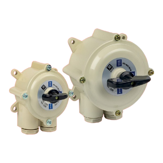
- Page 1 TECHNICAL MANUAL Rotary switches PV and PP EKF...
- Page 2 PV Х – ХХХ ХХ Х Rotary switch Number of poles Rated operating current, A Climatic version Housing material and IP rating: v1 - no housing, front bracket mounting, IP00. v3 - no housing, rear bracket mounting, IP00. E.g.: PV 1-16 М3 v.3 EKF...
-
Page 3: Technical Data
Housing material and IP rating: v1 - no housing, front bracket mounting, IP00. v3 - no housing, rear bracket mounting, IP00. E.g.: PP 2-40/N2 М3 v1 EKF 2 TECHNICAL DATA 2.1 For PV technical specifications, refer to figures and tables below. - Page 4 Table 1 Overall and installation Rated operating Wiring dimensions, mm Name current In (A) and diagram voltage Ue (V) PV 1-16 М3 v3 Fig. 10 16А 220V (DC) PV 2-16 М3 v3 Fig. 11 16А 230V (AC) PV 3-16 М3 v3 Fig.
- Page 5 - No housing; - Degree of protection: IP00; - Mounting with front bracket. Table 2 Rated operating Overall and installation current In (A) Wiring dimensions, mm Name and voltage diagram h1 h2 Ue (V) PV 1-16 М3 v1 Fig. 10 77 90 70 10 40 16А...
- Page 6 Rotary switches PV - carbolite housing Fig. 3 - Carbolite protective housing; - Degree of protection: IP30; - Mounting with housing base. Table 3 Overall and Rated operating installation Wiring Name current In (A) and dimensions, mm diagram voltage Ue (V) C1 С2 16А...
- Page 7 - High-impact flame retardant plastic housing; - Degree of protection: IP56; - Mounting with housing base. Glands’ connection: Table 4 Rated operating Overall and installation Glands’ current In (A) Wiring dimensions, mm Name connec- and voltage diagram tion C1 C2 Ue (V) PV 1-16 М1 Fig.
- Page 8 Rotary switches PV - silumin housing - Silumin protective housing; - Degree of protection: IP56; - Mounting with housing base. Glands’ connection: Fig. 5 Table 5 Rated Overall and installation operating dimensions, mm Glands’ Wiring Name current In (A) con- diagram and voltage nection...
- Page 9 2.2 For PP technical specifications, refer to figures and tables below. Rotary switches PP - version 3 - No housing; - Degree of protection: IP00; - Mounting with rear bracket. Fig. 6 Table 6 Overall and installation Rated operating Wiring dimensions, mm Name current In (A) and...
- Page 10 Rotary switches PP - version 1 Fig. 7 - No housing; - Degree of protection: IP00; - Mounting with front bracket. Table 7 Overall and installation Rated operating Wiring dimensions, mm Name current In (A) and diagram voltage Ue (V) h1 h2 PP 1-16/N2 М3 v1 Fig.
- Page 11 Rotary switches PP - plastic housing - High-impact flame-retardant plastic housing; - Degree of protection: IP56; - Mounting with housing base. Fig. 8 Glands’ connection: Table 8 Overall and installation Rated dimensions, mm operating Wiring Glands’ Name current In (A) dia- con- and voltage...
- Page 12 Rotary switches PP - silumin housing - Silumin protective housing; - Degree of protection: IP56; - Mounting with housing base. Fig. 9 Glands’ connection: Table 9 Rated Overall and installation operating dimensions, mm Wiring Glands' Name current In (A) diagram connection and voltage C1 C2...
- Page 13 For wiring diagrams, refer to figures 10-18. Rotary switches PV Fig. 10 - 1-pole rotary switch Fig. 11 - 2-pole rotary switch Fig. 12 - 3-pole rotary switch Fig. 13 - 4-pole rotary switch...
- Page 14 Fig. 14 - 1-pole 2-position rotary switch Fig. 15 - 2-pole 2-position rotary switch Fig. 16 - 3-pole 2-position rotary switch Fig. 17 - 4-pole 2-position rotary switch Fig. 18 - 3-pole reverse rotary switch...
- Page 15 Table 10 - Utilization categories Rated switching mode Rated Rated Utilization Electrical current, A voltage, V category Close, A Open, A endurance, O-C cycles 15 000 5000 5000 5000 AC-3 15 000 5000 5000 5000 5000 1000 AC-4 5000 1000 15 000 15 000 10 000...
- Page 16 Table 10 continued Rated switching mode Rated Rated Utilization Electrical current, A voltage, V category Close, A Open, A endurance, O-C cycles 10 000 10 000 15 000 AC-22 15 000 10 000 10 000 15 000 5000 5000 5000 AC-23 15 000 5000...
- Page 17 3 INSTALLATION AND OPERATION 1. Version with no housing Rotary switches shall be installed in dust-free rooms with no risk of accidental contact with the fixed contacts. Before installation, wipe the switches with a clean dry cloth to remove protective grease from metal surfaces and dust from insulating parts. Wire ends connected to 16-40A devices without end terminals shall be soldered.
-
Page 18: Delivery Scope
4 DELIVERY SCOPE 1. Rotary switch PV/PP - 1 pc. 2. Technical manual – 1 pc. 5 SAFETY REQUIREMENTS WARNING! Hazardous voltage. By protection method against electric shock, 16A rotary switches belong to protection class 1, while 40-100A rotary switches - to class 2 in compliance with to IEC 61140. -
Page 19: Manufacturer's Warranty
TOO «Energoresheniya Kazakhstan», Kazakhstan, Almaty, Bostandyk district, Turgut Ozal st., 247, apt 4. 8 CERTIFICATE OF ACCEPTANCE The rotary switches PV and PP EKF have been manufactured in compliance with laws and regulations in force and have been approved for operation. Date of manufacture: for information, refer to the product package.
Need help?
Do you have a question about the PP Series and is the answer not in the manual?
Questions and answers