Table of Contents
Advertisement
Quick Links
Advertisement
Table of Contents

Related Manuals for Renault SYMBIOZ 2024


Summary of Contents for Renault SYMBIOZ 2024
- Page 1 vehicle user manual...
- Page 3 Welcome aboard your vehicle This user manual contains the information required: – for you to familiarise yourself with your vehicle, to use it to its best advantage and to fully benefit from the all the functions and the technical developments it incorporates. –...
-
Page 4: Table Of Contents
CONTENTS Welcome aboard your vehicle ..........4 Driving ................. 139 Exterior ................4 Running in..............139 Passenger compartment ..........6 Starting, stopping the engine........140 Driver's position ............... 8 Gear control ..............143 Driving aids ..............10 Special features of petrol versions ......148 Safety on board ............. - Page 5 CONTENTS Breakdown recovery ............ 332 Headlights, lights: replacing bulbs ....... 338 Wiper blades: replacement.......... 342 Fuses ................344 Installation and use of accessories......349 Operating faults ............351 Technical specifications ............ 355 Information about the vehicle ........355 Replacement parts and repairs ........361 Service sheets .............
-
Page 6: 4 - We L C O M E A B O A R D Y O U R V E H I C L E
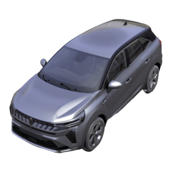
EXTERIOR 1 4 - We l c o m e a b o a r d y o u r v e h i c l e... - Page 7 EXTERIOR 1. Electric windows �� 295 1 Screen wiper, washer �� 131 Demisting �� 285 2. �� 30 card Locking, unlocking the doors �� 39 3. Rear view mirrors �� 122 4. Bodywork maintenance �� 317 5. Tyres �� 321 6. Lights: operation �� 124 Lights: replacement �� 338 Filling with fuel �� 137 We l c o m e a b o a r d y o u r v e h i c l e - 5...
-
Page 8: Passenger Compartment
PASSENGER COMPARTMENT 1 6 - We l c o m e a b o a r d y o u r v e h i c l e... - Page 9 PASSENGER COMPARTMENT 1. Adjusting your driving position �� 49 1 2. Passenger compartment storage/fit tings �� 301 3. Rear headrests �� 52 Rear bench seat �� 53 4. Transporting objects �� 305 5. Child safety �� 68 6. Front headrests �� 49 Front seats �� 49 We l c o m e a b o a r d y o u r v e h i c l e - 7...
-
Page 10: Driver's Position
DRIVER'S POSITION 1 8 - We l c o m e a b o a r d y o u r v e h i c l e... - Page 11 DRIVER'S POSITION 1. Instrument panel �� 115 1 2. Trip computer controls �� 100 3. Window wiper(s)/washer(s) control �� 131 4. Multimedia screen �� 293 5. Heated seat(s) �� 49 Heating system/air conditioning �� 285 6. Gear lever �� 143 7. Electronic parking brake �� 150 8. Engine start/stop button �� 140 9.
-
Page 12: Driving Aids
DRIVING AIDS 1 1 0 - We l c o m e a b o a r d y o u r v e h i c l e... - Page 13 DRIVING AIDS 1 – Driver correction devices and aids �� 167 – Lane departure prevention �� 172 – Emergency lane departure preven tion �� 179 – Active emergency braking �� 195 – Blind spot warning �� 186 – Parking exit warning �� 272 – Tyre pressure loss warning �� 163 –...
-
Page 14: Safety On Board
SAFETY ON BOARD 1 1 2 - We l c o m e a b o a r d y o u r v e h i c l e... - Page 15 SAFETY ON BOARD 1. Front airbags �� 60 1 2. Deactivating the passenger's front airbag �� 92 3. Curtain air bags �� 65 4. Seat belts �� 55 5. Side air bags �� 65 We l c o m e a b o a r d y o u r v e h i c l e - 1 3...
-
Page 16: Identifying A Vehicle - Labels
IDENTIFYING A VEHICLE - LABELS 1 1 4 - We l c o m e a b o a r d y o u r v e h i c l e... - Page 17 IDENTIFYING A VEHICLE - LABELS 1 1. Vehicle identification number re minder �� 355 2. Tyre pressure labels �� 163 �� 323 3. Engine identification �� 356 4. Technical information for the emer gency services �� 355 5. Vehicle identification plate �� 355 We l c o m e a b o a r d y o u r v e h i c l e - 1 5...
-
Page 18: The Engine Compartment (Routine Maintenance)
THE ENGINE COMPARTMENT (ROUTINE MAINTENANCE) 1 1 6 - We l c o m e a b o a r d y o u r v e h i c l e... - Page 19 THE ENGINE COMPARTMENT (ROUTINE MAINTENANCE) 1. Opening the bonnet �� 308 1 2. Electric traction system coolant �� 313 3. Battery �� 316 4. Brake fluid �� 314 5. Engine oil filler cap Engine oil dipstick �� 309 6. Screen washer fluid �� 315 7. Combustion engine coolant �� 312 We l c o m e a b o a r d y o u r v e h i c l e - 1 7...
-
Page 20: Breakdown Recovery
BREAKDOWN RECOVERY 1 1 8 - We l c o m e a b o a r d y o u r v e h i c l e... - Page 21 BREAKDOWN RECOVERY 1 1. Replacing windscreen wiper blade(s) �� 342 2. Puncture �� 328 Tools �� 327 Emergency spare wheel �� 328 Changing a wheel �� 330 3. Fuses �� 344 4. Rear towing point �� 332 5. Replacement of the direction indica tor lights �� 338 6 Replacing the rear screen wiper blade �� 342 7.
-
Page 22: E-Tech Full Hybrid Vehicle
E-TECH FULL HYBRID VEHICLE 1 2 0 - We l c o m e a b o a r d y o u r v e h i c l e... - Page 23 E-TECH FULL HYBRID VEHICLE 1. Coolant �� 313 1 2. Warning lights �� 115 Displays and indicators �� 107 "E-save" mode �� 28 3. Multimedia screen 4. Regenerative braking change pad 5. Battery �� 316 6 Towing breakdown recovery �� 332 We l c o m e a b o a r d y o u r v e h i c l e - 2 1...
-
Page 24: Getting To Know Your Vehicle
E-TECH FULL HYBRID Introduction 2 2 2 - G e t t i n g t o k n o w y o u r v e h i c l e... - Page 25 E-TECH FULL HYBRID As with any battery, it discharges when the warning light is displayed in blue 1 Secondary "12 V" battery it is used. The traction battery is (�� 107). 2 "230 volt" traction battery charged: Failure to do so may result in damage 2 ...
- Page 26 E-TECH FULL HYBRID "230 V" electrical circuit The electrical system of the hybrid vehicle uses 2 direct voltage of approxi mately 230 V. This system can get hot during and after switching off the ignition. Observe the warning messages on the labels in the vehicle. All operations on or modifications to the "230 V"...
-
Page 27: Operation
E-TECH FULL HYBRID Instrument panel B Operation Your hybrid vehicle is The hybrid system selects the com very quiet. When getting bustion engine and/or the electric en 2 out of the vehicle, al gine according to the driving style ways check that the gear (smooth, sporty, etc.), the traffic condi tions and driving mode selected �� selector is in P position, apply the 283. - Page 28 E-TECH FULL HYBRID Depending on the driving mode select convert(s) the energy produced by the ed, the various energy flows D are vehicle deceleration into electric ener shown on the instrument panel. 2 These are energy flows between: This is used to brake the vehicle and recharge the traction battery. –...
- Page 29 E-TECH FULL HYBRID Special case When the traction battery 2 reaches a maximum charge level, the engine brake is tem porarily reduced. Please adapt your driving style appropriately. The engine brake should under no circumstances be used as a substitute for the brake pedal. Flow G "Energy recovery" The colour of flows varies: –...
- Page 30 E-TECH FULL HYBRID Activation, deactivation of the "E- The warning light 10 displayed save" function on the instrument panel informs you that the hybrid system is using only the 2 electrical assembly to power the vehi cle movement. Note: when the traction battery level is low, the vehicle automatically switches to hybrid mode and the combustion engine starts: the 10...
-
Page 31: Important Recommendations
E-TECH FULL HYBRID Important recommendations 2 Please read these instructions carefully. Failure to follow these instructions may lead to a risk of fire, serious in jury or electric shocks which could result in death. In the event of an accident or impact In the event of an accident or an impact to the underside of the vehicle (e.g. -
Page 32: Card
CARD "Remote lighting" function General information If the battery is flat, you can still lock/unlock and start 2 your vehicle �� 39, �� 140. Range Make sure that the correct battery type is being used, and that the battery is in good condition and inserted correctly. Its service life is approximately two years: it should be replaced when the "Keycard Battery Low" message ap... - Page 33 CARD Fitting a strap 7 Recommendations Driver's responsibility Avoid leaving the card in when parking or stop 2 hot, cold or humid areas. ping the vehicle Do not keep the card in a place Never leave an animal, where it could be bent or dam child or adult who is not selfsuffi aged accidentally, such as in your cient alone in your vehicle, even back pocket.
- Page 34 CARD Insert the hand strap into the compo nent 8 and pass the end of the strap Do not store the card any Driver's responsibility through the buckle. where it may come into when parking or stop 2 Position the strap at the opening 6 and contact with other electron ping the vehicle close the casing. ic equipment (computer, phone Never leave an animal, Note: check that the diameter of the...
- Page 35 CARD "Handsfree" unlocking when ap "Hands-free" locking when moving proaching the vehicle away from the vehicle 2 If the card 4 has been within the de tection zone 3 for approximately 15 minutes, remote locking is deactivated. With the card in the access zone 2 , With the card on you and the doors To lock the vehicle, press the button 5 the vehicle will be unlocked.
- Page 36 CARD Using the card as a remote control utes after the vehicle has been The hazard warning lights flash twice locked; to indicate that the vehicle is locked – after several passes in the vicinity of and, depending on the vehicle, the 2 zone 2 without the doors having door mirrors fold in automatically.
- Page 37 CARD After a door is opened and closed Deadlocking Locking is confirmed by two slow while the engine is running, if the flashes and three quick flashes of card is no longer in zone 3 , the "Card the hazard warning lights and side re not detected" message warns you that peaters.
- Page 38 CARD Operating faults Note: when replacing the battery, do not touch the electronic circuit or con If the battery is too weak to ensure cor tacts on the card. rect operation, you will still be able to 2 start and lock/unlock the vehicle �� 39. The batteries are available from approved Dealers, and their service life ap proximately two years. Check that there is no dye on the battery: risk of an incorrect electrical contact.
- Page 39 CARD Precautions relating to batteries: 2 – keep batteries (new or used) out of reach of children; – do not swallow batteries; Risk of chemical burns which may lead to death. – if ingested or inserted into any part of the body, consult a doctor as soon as possible.
-
Page 40: Doors And Opening Elements
DOORS AND OPENING ELEMENTS Rear doors Opening from the inside Opening and closing the doors 2 Opening from the outside Front doors Pull the handle 3 . With the doors unlocked or the card on you, hold the handle 2 and pull it to Depending on the vehicle, it may be wards you. - Page 41 DOORS AND OPENING ELEMENTS ing buzzer will sound when a door is around 40 seconds until the door or opened. luggage compartment is closed. Driver's responsibility when parking or stop Door or luggage compartment lid Child safety 2 ping the vehicle open buzzer Never leave an animal, child or adult who is not selfsuffi...
- Page 42 DOORS AND OPENING ELEMENTS Using the key integrated in the – the vehicle is located in a high elec card tromagnetic radiation zone. It is then possible: 2 – to use the hands-free card's built-in emergency key to unlock the driver’s door; – to use the interior door locking/un locking control; The card's built-in key Access with key 2 The built-in key 2 can be used to lock or unlock the driver's door when the card is not working.
- Page 43 DOORS AND OPENING ELEMENTS Locking the doors manually Interior locking/unlocking door con Door and tailgate status indicator trol With the ignition on, the switch 7 warning light indicates the locking sta 2 tus of the opening elements: – when the warning light is on, the doors and luggage compartment door are locked;...
-
Page 44: Automatic Locking When Driving
DOORS AND OPENING ELEMENTS open, press and hold the switch 7 for After the vehicle is started, the system ments are properly closed. If they are more than five seconds. automatically locks the doors when properly closed, contact an approved you reach approximately 6 mph (10 dealer. -
Page 45: Luggage Compartment
DOORS AND OPENING ELEMENTS To close Luggage compartment – access the luggage compartment by folding down the rear bench seatback(s); To open – insert a pencil or similar object into 2 the recess 3 and slide the unit as shown in the illustration; –... - Page 46 DOORS AND OPENING ELEMENTS Opening/Closing Using the tailgate exterior opening control As a safety precaution, The opening or closing of the mo the doors should only be torised tailgate is indicated by three 2 opened/closed when the sound signals. vehicle is stationary. Risk of injury. Ensure that nobody is close to the moving parts using the remote control card when opening/closing...
- Page 47 DOORS AND OPENING ELEMENTS Using the tailgate interior closing Using the dashboard control Using the "hands-free" function control (depending on the vehicle) 2 To open the tailgate, press and hold Press the control 3 . the switch 4 until you hear the beep, The "handsfree" function enables al...
- Page 48 DOORS AND OPENING ELEMENTS Obstacle detection Note: with the tailgate open, after de tecting a closure control, it waits Deactivate the "hands- If the tailgate detects an obstacle dur around three seconds before triggering free" function before ing its manoeuvre then it will stop. It 2 the closure (a beep is emitted every you: will then be released from the obstacle second).
- Page 49 DOORS AND OPENING ELEMENTS – manually adjust the tailgate to the case, operate the automatic tailgate The obstacle detection is chosen position; with the engine started. – press the motorised tailgate control an aid to opening and Note: in very cold weather conditions, 3 for more than three seconds to save 2 ...
- Page 50 DOORS AND OPENING ELEMENTS The attaching of any car rying device (bike rack, 2 luggage box, etc.) rest ing on the luggage com partment lid is prohibited. To in stall a carrying device on your ve hicle, contact an approved dealer. 4 8 - G e t t i n g t o k n o w y o u r v e h i c l e...
-
Page 51: Front Seats
FRONT SEATS Press the button 2 and lift the head Front headrests rest to release it. The headrest is an im portant safety compo To refit the headrest 2 To raise the headrest nent: ensure that it is in place and in the correct Check that the headrest rods are clean position. - Page 52 FRONT SEATS To move the seat forwards or back Central armrest Move the switch 2 forwards or back wards or, depending on the vehicle, lift Move the switch 1 forwards or back the handle 5 and tilt the seatback to wards or, depending on the vehicle, lift 2 the desired position. Release the han...
- Page 53 FRONT SEATS To adjust the seat’s lumbar position Heated seats Consult an approved dealer. 2 Lower the handle 7 to increase the Ignition on: support and lift it to decrease it. – pressing the switch 8 on the re quired seat for the first time activates the heating system on high. Both of the built-in warning lights on the switch light up;...
-
Page 54: Rear Seats
REAR SEATS To refit the headrest Rear headrests Enter the rods in their housing and push down the headrest until it locks to 2 Position for use use it in the high position. The side headrests are not adjustable. Check that it is correctly locked. Raise the central headrest fully until it Central headrest storage position 2 locks. -
Page 55: Rear Bench Seat: Functions
REAR SEATS To move a seat forwards or back Rear bench seat: functions To replace the seatback, proceed in wards the reverse order to removal. Raise the seatback again until it reach 2 es the locking joint of the seatback. Be careful not to jam the safety strap between the backrest and the parcel shelf. - Page 56 REAR SEATS When moving the rear seats, ensure that noth 2 ing obstructs the anchor age points (passenger's arm or leg, a pet, gravel, cloth, toys, etc.). 5 4 - G e t t i n g t o k n o w y o u r v e h i c l e...
-
Page 57: Seat Belts
SEAT BELTS Adjusting the seat belts Seat belts Make sure that the rear bench seat �� 52 is locked Always wear your seat belt when trav 2 in position correctly so that elling in your vehicle. You must also the rear seat belts will operate comply with the legislation of the par correctly. ticular country you are in. - Page 58 SEAT BELTS The seat belt must be worn as close to With the doors closed, the graphic 6 is the body as possible. e.g. avoid wear displayed on the instrument panel for ing heavy clothing, keeping bulky ob approximately 60 seconds when the 2 jects under the belts, etc. vehicle ignition is switched on. This in forms the driver of the fastening status Locking of each of the front seat belts every time:...
- Page 59 SEAT BELTS When the vehicle speed exceeds ap – the doors are opened during driving proximately 12 mph (20 km/h), if one (vehicle speed above zero); – a beep sounds for around 30 or 120 – a front seat belt is fastened/unfas of the front seat belts is or becomes seconds;...
-
Page 60: Rear Seat Belts
SEAT BELTS Adjusting the height of the front Rear centre seat belt Rear seat belts seat belts Rear side seat belts 2 Slowly unwind the belt 9 . Press the button 7 to adjust the seat Click the buckle 10 into the black belt height, so that the shoulder strap The locking, unlocking and adjustment catch 11 . - Page 61 SEAT BELTS Warnings The following information applies to the vehicle’s front and rear seat belts. 2 – No modification must be made to the originally-fitted restraint system components (seat belts, seats and their mountings). For special operations (e.g. fitting child seats) please contact an approved dealer. –...
-
Page 62: Additional Safety Devices
ADDITIONAL SAFETY DEVICES Pretensioners Methods of restraint in addition – Have the entire re to the front seat belts straint system checked 2 following an accident. Depending on the vehicle, they may comprise: – No operation whatsoever is per mitted on any part of the system – seat belt inertia reel pretension (pretensioners, Airbags, comput... - Page 63 ADDITIONAL SAFETY DEVICES Driver and passenger front airbags Operation The airbag system uses Fitted to the driver and passenger This system is only operational when pyrotechnic principles. sides. the ignition is switched on. 2 This explains why, when A symbol on the lower section of the In a severe frontal impact, the airbags the airbag inflates, it will windscreen indicates if this equipment...
- Page 64 ADDITIONAL SAFETY DEVICES 2 The following cases trigger the pre In a side impact with another vehi In the event of a frontal impact with tensioners or airbags. another vehicle of an equivalent or cle of an equivalent or higher cate higher category, with an impact area gory, at an impact speed equal to or In a frontal impact against a rigid...
- Page 65 ADDITIONAL SAFETY DEVICES 2 In the following examples, the pre – side impact at the front or rear of the The pretensioners or airbags may be triggered in the following cases: tensioners or airbags might not be vehicle; triggered: – frontal impact, underneath the tail of –...
- Page 66 ADDITIONAL SAFETY DEVICES Warnings All of the warnings below are given so that the airbagis not obstructed in any way when it is inflated and also to pre 2 vent the risk of serious injuries caused by items which may be dislodged when it inflates. Warnings in relation to the driver's airbag –...
-
Page 67: Methods Of Restraint In Addition To The Rear Seat Belts
ADDITIONAL SAFETY DEVICES Side seat belt pretensioners Methods of restraint in addition – Have the entire re to the rear seat belts straint system checked 2 following an accident. Depending on the vehicle, they may comprise: – No operation whatsoever is per mitted on any part of the system –... - Page 68 ADDITIONAL SAFETY DEVICES of the seats (door side) to protect the – The airbag is deployed through occupants in the event of a severe Warning related to the slits in the front seatbacks (door side impact. side airbag side): never insert any objects in 2 to these slits.
-
Page 69: Additional Methods Of Restraint
ADDITIONAL SAFETY DEVICES Additional methods of restraint All of the following warnings are intended to ensure that the airbag is not obstructed in any way when it is inflated and 2 also to prevent the risk of serious injuries caused by items which may be projected when it inflates. The airbag is designed to complement the action of the seat belt. -
Page 70: Child Safety
CHILD SAFETY General information A collision at 31 mph (50 Driver's responsibility km/ h ) is the same as when parking or stop 2 Carrying children falling a distance of 10 ping the vehicle metres. Never leave an animal, Please ensure that you comply with Transporting a child without a re... - Page 71 CHILD SAFETY proved Dealer to find out which seats are recommended for your vehicle. Set a good example by al Never leave a child unat ways fastening your seat tended in the vehicle. The regulations on transporting chil 2 dren are specific to each country. The belt and teaching your Check that your child is use of a child seat during transport de...
- Page 72 CHILD SAFETY Forward-facing child seats Booster cushions Choosing a child seat Rear-facing child seats 2 Up to 18 kg or 4 years, the child may From 15 kg or 4 years, the child can travel on a forward-facing seat. travel using a booster seat, which will Choose a seat according the child's enable the seat belt to be adapted to A baby’s head is, proportionally, heav...
-
Page 73: Choosing A Child Seat Mounting
CHILD SAFETY Ensure that the strap paths indicated List of manufacturer's rec by the child seat manufacturer are ob The seat belt must never served. ommended methods of re be twisted or the tension 2 straint for children: Always check that the seat belt is cor relieved. Never pass the rectly fastened by pulling it up, then shoulder strap under the pulling it out fully whilst pressing on the arm or behind the back. - Page 74 CHILD SAFETY prevent the child seat from moving in the event of a collision. The ISOFIX anchoring points have been exclu In the latter three cases check that 2 your child seat can be installed by con sively designed for child sulting the list of compatible vehicles. seats equipped with the ISOFIX system. Never fit a differ...
- Page 75 CHILD SAFETY The ISOFIX anchoring points have been exclu 2 sively designed for child seats equipped with the ISOFIX system. Never fit a differ ent type of child seat, seat belt or other objects to these fittings. Check that nothing is obstructing the anchorage points. If your vehicle has been involved in a road accident, have the ISOFIX anchorage points checked and replace your child...
-
Page 76: Child Seats
CHILD SEATS ent child seat, check with the manufac Fitting a child seat, general in turer that it can be fitted. RISK OF DEATH OR formation SERIOUS INJURY: be 2 In the front seat fore fitting a rear facing Some seats are not suitable for fitting child seat on the front The laws concerning children travelling child seats. - Page 77 CHILD SEATS Ensure that the child Installing a booster Fit the child seat in a seat or the child's feet do seat (group 2 or 3) rear seat wherever pos 2 not prevent the locking in Check that the seat belt sible. �� 55 operates (winds) place of the seat in front To install an ISOFIX �� 52 or �� 49.
- Page 78 CHILD SEATS Attachment by seat belt 2 Fitting diagram 7 6 - G e t t i n g t o k n o w y o u r v e h i c l e...
- Page 79 CHILD SEATS Check the status of the airbag before fitting a child seat or allowing a passenger to use the seat. 2 Seat not suitable for fitting child seats. Child seat attached using the belt Seat equipped for attaching a "universal" approved seat using a seatbelt. Seat enabling a child seat with "B2"...
- Page 80 CHILD SEATS Installation table The table below summarises the information shown on the installation diagram in order to ensure the regulations in 2 force are respected. Front passenger seat Weight of the Rear centre Type of child seat Rear side seats With airbag de...
- Page 81 CHILD SEATS (1) RISK OF DEATH OR SERIOUS INJURY: before fitting a rear-facing child seat in this seat, make sure that the front passenger airbag has been deactivated�� 92. 2 X = Seat not suitable for fitting child seats of this type. U = Seat enabling a child seat with "Universal"...
- Page 82 CHILD SEATS Attachment using the ISOFIX system 2 Fitting diagram Version with front passenger seat equipped with ISOFIX 8 0 - G e t t i n g t o k n o w y o u r v e h i c l e...
- Page 83 CHILD SEATS For the front passenger seat, the use of a child seat with a floor support is recommended to avoid triggering the seat 2 belt warning signal. Using a child safety system which is not approved for this vehicle will not properly protect the baby or child. They risk serious or even fatal injury.
- Page 84 CHILD SEATS Fitting a seat ISOFIX in the rear-left seat means the middle seat cannot be used. The central seat belt will no longer be either accessible or useable. 2 8 2 - G e t t i n g t o k n o w y o u r v e h i c l e...
- Page 85 2 G e t t i n g t o k n o w y o u r v e h i c l e - 8 3...
- Page 86 CHILD SEATS Installation table Version with front passenger seat equipped with ISOFIX 2 The table below summarises the information shown on the installation diagram in order to ensure the regulations in force are respected. Front passenger seat Without Weight of the Size of seat Rear side Rear centre...
- Page 87 CHILD SEATS Front passenger seat Without Weight of the Size of seat Rear side Rear centre Type of child seat 2 airbag or with With airbag child [fixture] seats seat airbag deacti activated vated 48.5 to 79.4 lbs) Rear-facing seat i - U (1) (5) i - U (2) Seati-Size...
- Page 88 CHILD SEATS – F3,F2,F2X [A, B, B1]: for forward-facing seats in group 1 (9 to 18 kg); – B2, B3: boosters in groups 2 and 3 (15 to 25 kg and 22 to 36 kg); – R3, R2 [C, D]: rear-facing seats or shell seats in group 0+ (less than 13 kg) or group 1 (9 to 18 kg); 2 –...
- Page 89 2 G e t t i n g t o k n o w y o u r v e h i c l e - 8 7...
- Page 90 CHILD SEATS Fitting diagram Version with front passenger seat not equipped with the ISOFIX 2 8 8 - G e t t i n g t o k n o w y o u r v e h i c l e...
- Page 91 CHILD SEATS For the front passenger seat, the use of a child seat with a floor support is recommended to avoid triggering the seat 2 belt warning signal. Using a child safety system which is not approved for this vehicle will not properly protect the baby or child. They risk serious or even fatal injury.
-
Page 92: Installation Table
CHILD SEATS Installation table Version with front passenger seat not equipped with the ISOFIX 2 The table below summarises the information shown on the installation diagram in order to ensure the regulations in force are respected. Weight of the Size of seat [fix Front passen... - Page 93 CHILD SEATS IUF = Seat allowing a child seat with "Universal or vehicle-specific" approval to be attached using the ISOFIX system on equipped vehicles; check that it can be fitted. IL = Seat allowing a child seat with "Semi-universal or vehicle-specific" approval to be attached using the ISOFIX system on 2 ...
-
Page 94: Child Safety: Deactivating, Activating The Front Passenger Airbag
CHILD SAFETY: DEACTIVATING, ACTIVATING THE FRONT PASSENGER AIRBAG – you must deactivate the airbag Warning when using a rear-facing child seat. DANGER As the operation of the 2 front passenger airbag is The passenger airbag not compatible with the may only be activated or positioning of rear-facing child deactivated while the ve... - Page 95 CHILD SAFETY: DEACTIVATING, ACTIVATING THE FRONT PASSENGER AIRBAG Activation of the front passen ger airbag 2 To reactivate the airbag: with the ve The markings on the dashboard and the labels A on each side of the pas hicle stationary and the ignition senger sun visor 3 (see example of la switched off, press and turn the lock You must reactivate the airbag as soon 1 to the ON position.
- Page 96 CHILD SAFETY: DEACTIVATING, ACTIVATING THE FRONT PASSENGER AIRBAG tion system, the warning lights are displayed on the in 2 strument panel. Switch off the ignition and check the position of the lock 1 . Switch the ignition back on: the warn ing lights go out. If the problem persists, it signals a sys tem failure. In this case, it is prohibited for a rear-facing child seat to be fitted to the front passenger seat or for any other passenger to occupy the seat.
- Page 97 2 G e t t i n g t o k n o w y o u r v e h i c l e - 9 5...
-
Page 98: Driving Position
DRIVING POSITION Driving position: left-hand drive 2 9 6 - G e t t i n g t o k n o w y o u r v e h i c l e... - Page 99 DRIVING POSITION – activating/deactivating the electronic – "E-Save" charging level preservation The fittings described below DE parking brake; – lighting dimmer for control instru PEND ON THE VEHICLE VERSION – activating/deactivating the autohold ments; AND COUNTRY. function. – electric headlight beam adjustment; 2 1. Side air vents. –...
-
Page 100: Driver's Position, Righthand Dri Ve
DRIVING POSITION Driver’s position, righthand dri 2 9 8 - G e t t i n g t o k n o w y o u r v e h i c l e... - Page 101 DRIVING POSITION – trip computer information read-out – door central locking; The fittings described below DE and vehicle settings customisation – ... PEND ON THE VEHICLE VERSION menu; AND COUNTRY. – remote radio and navigation system. 2 1. Side air vents. 25.
-
Page 102: Trip Computer
TRIP COMPUTER Vehicle fitted with instrument panel General information 2 Trip computer A or B Depending on the vehicle, this in cludes the following functions: – mileage; The functions are displayed in zone 5 – trip settings; Select the functions by repeatedly – information messages; pressing switch 2 or 3 . - Page 103 TRIP COMPUTER Vehicle fitted with instrument panel – mileage; range increases as you travel. This – average speed; range takes into account the average fuel consumption since the last time c) trip mileage recorder and average the reset button was pressed. There 2 speed; fore, the average fuel consumption d) reset the tyre pressures;...
- Page 104 TRIP COMPUTER Journey settings The display of information shown below DEPENDS ON THE VEHICLE EQUIPMENT AND COUNTRY. 2 Examples of selections Interpreting the display selected a) Trip log. Successive display: No stored message – information messages (passenger airbag OFF etc.); – operating fault messages (check the injection system, etc.). b) Current fuel consumption.
- Page 105 TRIP COMPUTER Examples of selections Interpreting the display selected Onboard computer with mileagebe 2 fore-service message d) Mileage before service and oil change. Service in 18,641 miles (30,000 km)/12 Service distance months With the ignition on and the engine not running, access the "Mileage before service"...
-
Page 106: Information Messages
TRIP COMPUTER Information messages These can help in the vehicle starting phase, or give information about a selection or a driving status. 2 Examples of information messages are given in the following pages. Examples of messages Interpreting the display selected "Parking brake applied"... - Page 107 TRIP COMPUTER Operating fault messages 2 These appear with the warning light to inform you that you should drive very carefully to an approved dealer as soon as possible. If you fail to follow this recommendation, you risk damaging your vehicle. They disappear when the display selection key is pressed or after several seconds and are stored in the computer log.
-
Page 108: Warning Messages
TRIP COMPUTER Warning messages 2 These appear with the warning light and require you to stop immediately, for your own safety, as soon as traf fic conditions allow. Stop your engine and do not restart it. Call an approved Dealer. Some examples of warning messages are given below. -
Page 109: Displays And Indicators
TRIP COMPUTER Speedometer 1 Displays and indicators Multimedia information 2 2 Instrument panel A Depending on the vehicle, you can dis play information from the multimedia screen (compass, telephone, naviga tion, etc.) or information from the trip computer. Please refer to the multimedia instruc tions for more information. Estimated range with remaining fu el 3 The value is displayed after driving 400 metres �� 100. - Page 110 TRIP COMPUTER Coolant temperature indicator 8 Trip computer/Multimedia informa Depending on the vehicle, you can tion 10 customise your instrument panel with In normal use, the indicator 8 should the content and colours of your choice. be located before zone 7 . Depending on the vehicle, you can dis...
- Page 111 TRIP COMPUTER Direction indicators 16 and 20 Special features of ETech Full Hy Fill up as soon as possible. brid versions Warning light 17 2 �� 115 Tyre under-inflation warning light �� 163 Airbag warning light 19 �� 60 Electronic parking brake warning light 21 �� 150 "Hands off steering wheel" detec It lights up when the ignition is tion warning light 22 switched on.
- Page 112 TRIP COMPUTER Speedometer 25 Energy flow indicator 29 If the charge level continues to drop, the electric range value will no longer �� 22 Depending on the style selected, the be displayed. display varies. 2 If possible, stop the vehicle when traf Charge meter 30 fic conditions allow it. "230 V" traction battery level re...
- Page 113 TRIP COMPUTER Fuel gauge 34 Combustion engine temperature Engine oil level low warning display 36 If the level is at the minimum, warning 2 light integrated in the indicator comes on orange, accompanied by a beep. Whatever the remaining battery level, fill the tank as soon as possible.
-
Page 114: Vehicle Settings Personalisation Menu
TRIP COMPUTER Instrument panel in miles From the multimedia screen 1 Please refer to the multimedia instruc tions for more information. 2 To use certain driving aid functions, it is necessary to change the unit of mea surement on the instrument panel in order to obtain the appropriate information when driving in a country where the speed units dif... - Page 115 TRIP COMPUTER On the instrument panel – Remote locking/approach unlocking; – Language; – Remote locking sound; – Unit; – Silent mode; – Style; – Automatic locking; – Colour. 2 c) "Wiping and lighting": "VEHICLE": – Wiping in reverse; – Rear windscreen wiping in reverse –...
- Page 116 TRIP COMPUTER "ACCESS": The vehicle settings per Exterior temperature – Lock doors during driving; sonalisation menu cannot indicator – Hands-free opening/closing; 2 – Unlocking the driver’s door only; be used when driving. As ice formation is relat – Automatic re-locking; At a speed exceeding 12 mph (20 ed to climatic exposure, –...
-
Page 117: Warning Lights
WARNING LIGHTS Instrument panel A or B : it illumi The display of information shown nates when the ignition is switched on. If no lights or sounds are below DEPENDS ON THE VEHICLE apparent, this indicates a EQUIPMENT AND COUNTRY. To adjust the brightness, see the multi 2 media user manual. - Page 118 WARNING LIGHTS fluid level in the circuit is low or that gine is switched on and goes off after a Tell-tale light forairbag there is a braking system fault. few seconds. It lights up when the ignition or the en Stop as soon as traffic conditions allow If it comes on while driving, alongside gine is switched on and goes off after a 2 and consult an approved Dealer.
- Page 119 WARNING LIGHTS approved dealer as soon as possible. Particle filter system warning Mode warning light ECO Meanwhile, drive with care. light �� 148 This lights up when ECO mode is acti If you fail to follow this recommenda vated �� 157. tion, you risk damaging your vehicle. 2 Tyre under-inflation warning Coolant temperature warning Electronic parking brake ap light plied warning light �� 150 This lights up when the ignition is...
- Page 120 WARNING LIGHTS Hands-free parking warning warning light, a beep and If the vehicle is parked light �� 261 the "EVACUATE IN SAFETY" mes on the hard shoulder, sage, switch off the ignition and do not 2 you must warn other restart the engine. Leave the vehicle Lane departure preven...
- Page 121 WARNING LIGHTS the reserve level �� 107. Electric operating mode warn 2 ing light It is displayed when only the electric motor and traction battery are power ing the movement of the vehicle �� 22. Electrotechnical motor fault warning light When it comes on, this indicates an electrotechnical fault related to the electrical assembly (traction battery and electric motor). Contact your ap...
-
Page 122: Steering
STEERING Steering wheel heating The function switches off automatically Adjusting the steering wheel after the regulation phase of approxi mately 30 minutes. The indicator light height and depth 2 built into the switch 3 stays on. Note: if the function has switched off automatically, press the switch 3 twice to reactivate it. - Page 123 STEERING Special case With the engine switched Depending on the vehicle, in the event off, or if there is a system of a battery fault (disconnected, dis 2 fault, it is still possible to charged battery, etc.), the steering turn the steering wheel. The force wheel angle must be reset.
-
Page 124: Rear View Mirrors
REAR VIEW MIRRORS Electrical folding mirrors Exterior rear view mirrors Objects observed in the The door mirrors will foldout automati rear view mirror glass cally when the vehicle is unlocked. The 2 are actually closer than door mirrors fold in when the vehicle is they appear. For your locked. - Page 125 REAR VIEW MIRRORS cle behind, shift the small lever 4 lo cated behind the rear view mirror. Rear view mirror without lever 4 2 The rear view mirror automatically darkens when you are being followed by a vehicle which illuminates you or in very bright lighting.
-
Page 126: Lighting And Signals
LIGHTING AND SIGNALS strument panel to inform you that it is Exterior lighting and signals not possible to activate the side lights. Before driving at night, check that the electrical 2 Daytime running lights function equipment is operating correctly and adjust the The daytime running lights are activat... - Page 127 LIGHTING AND SIGNALS During deactivation of the main beam The main beam headlights come on push the stalk 1 . Warning light headlights, the dipped beam head automatically if: comes on the instrument panel. lights return to their original position. – the exterior light level is low; 2 ...
- Page 128 LIGHTING AND SIGNALS Switching off the lights Lights-on reminder audible alarm Using a portable naviga If the lights are on after the engine is tion system at night in switched off, a warning beep sounds 2 the windscreen area be when the driver’s door is opened to low the camera may dis warn you that the lights are still on. turb the operation of the "auto...
- Page 129 LIGHTING AND SIGNALS Activating/deactivating the function Switching off the lights sition or, depending on the vehicle, to the 0 position. For activation or deactivation of the ex Rotate the centre ring 4 again to align ternal welcome, refer to the multimedia the mark 3 with the symbol for the fog Rear fog lights 2 ...
-
Page 130: Headlight Beam Adjustment
LIGHTING AND SIGNALS Headlight beam adjustment 2 Switch A is used to adjust the height of the headlight beams according to the load. With the dipped beam headlights on, press or raise switch A as many times as required to select the required posi tion on the instrument panel. Note: depending on the vehicle, when the engine is started, the position se... - Page 131 LIGHTING AND SIGNALS Table of adjustment position examples Examples of positions for adjusting 2 the control A according to the load Driver alone or with front passenger 0 or 1 All seats occupied 1 or 2 Driver with passengers and luggage (or load) reaching the maximum permis 2 or 3 sible all-up weight Driver without passengers and luggage (or load) reaching the maximum per...
-
Page 132: Audible And Visual Signals
AUDIBLE AND VISUAL SIGNALS will return to its original position and Horn the direction indicator light concerned will flash three times. 2 Hazard warning lights Press the steering wheel boss A to sound the horn. Headlight flasher Press switch 2 to activate all To flash the headlights, pull the stalk 1 four direction indicator lights and side towards you, then release. -
Page 133: Wiper
WIPER For example, fast wiping speed will Windscreen washer, wiper slow to normal wiping speed. As soon as the vehicle moves off, wip 2 Vehicle fitted with intermittent ing will return to the speed originally windscreen wipers selected. Any action on the stalk 1 overrides and cancels the automatic function. Vehicle fitted with front windscreen wiper rain sensor A. - Page 134 WIPER The higher the sensitivity, the quicker The rain sensor operation may be in the wipers will react and the faster the terrupted in the event of: wipe. – damaged windscreen wipers: a film 2 When activating automatic wiping or of water or traces left by a blade in the when increasing sensitivity, one sweep sensor's detection zone may increase of the blades is performed.
- Page 135 WIPER nism. If you activate the wipers while the blades are stuck down with ice, In the event of obstacles on you may risk damaging both the blade the windscreen (dirt, snow, and the wiper motor. 2 ice etc.), clean the wind – Do not activate the wipers on a dry screen (including the central area screen.
- Page 136 WIPER With the ignition on, pull the stalk 1 Rear windscreen wash, wiper then release. Efficiency of a wiper Rear windscreen wiper blade A longer pull will trigger, in addition to 2 the windscreen washer, two sweeps of Check the condition of the the wipers followed, a few seconds lat...
- Page 137 WIPER When washing using a roller type car menu, you can opt to activate or deac tivate this function �� 112. wash, return the ring 3 on the stalk 1 Efficiency of a wiper to the stop position to deactivate auto blade For vehicles not fitted with a settings matic wiping. 2 Check the condition of the customisation menu, you can have this Follow usage recommendations.
- Page 138 WIPER few seconds later, by a third (drip wip ing function). When the stalk is released, it returns to 2 the rear wipe position. 1 3 6 - G e t t i n g t o k n o w y o u r v e h i c l e...
-
Page 139: Fuel Tank
FUEL TANK Fuel filler cap: this is a specific type. 2 If you have to replace it, make sure it is identical to the original cap. Contact an ap proved Dealer. Never place the cap near a source of heat or flame. Do not wash the filler area with a high pressure washer. -
Page 140: Filling With Fuel
FUEL TANK To do this, with the ignition off, fill up After filling, check that the with fuel or top up with at least approx Persistent smell of fuel imately 2.20 gallons (10 litres) then cap and cover are closed. If you notice a persistent 2 start the engine to operate the pump fuel odour you should: and renew the fuel in the circuit. -
Page 141: Driving
RUNNING IN For the first 620 miles (1,000 km) do not exceed 80 mph (130 km/h) in the highest gear, or 3,000 to 3,500 rpm. You can only expect top performance from your vehicle after approximately 1,860 miles (3,000 km). 3 ... -
Page 142: Starting, Stopping The Engine
STARTING, STOPPING THE ENGINE "Set gearbox to P" message appears Ignitionstarter switch on a vehi on the instrument panel; – in some cases it is necessary to cle with card move the steering wheel while press ing the start button 2 to help unlock the steering column – in this case 3 the Turn steering wheel + START" message will inform you. Driver's responsibility when parking or stop... - Page 143 STARTING, STOPPING THE ENGINE Once you have gained access to your Never switch off the ig vehicle, you may use some of its func tions (radio, navigation, wipers, etc.). nition before the vehi cle has come to a com To use the other functions, with the card in the passenger compartment, plete stop. Once the en...
- Page 144 STARTING, STOPPING THE ENGINE area 3 . Press the button 2 to start the and you attempt to switch of the en vehicle. The message goes out. gine, the "Card missing press and hold Driver's responsibility START" message appears on the in when parking or stop Conditions for stopping the engine strument panel: press and hold the ping the vehicle button 2 for more than three seconds.
-
Page 145: Gear Control
GEAR CONTROL Automatic gearbox, electronic lever Electronic selector lever 3 4. : position of the engaged gear; The triangle 7 is displayed when man ual mode is activated. 5. : position accessible from the cur rent position by moving the selector lever 1 one notch forwards or back Check that the P indica wards; tor light on the instru 6. : position accessible from the cur 1 electronic selector lever ment panel and the indi... - Page 146 GEAR CONTROL One-touch selector To engage position P and the warning light are dis played on the instrument panel. Note: – if the driver opens their door to leave the vehicle and P position has not 3 been engaged, a beep sounds and the "P not engaged"...
- Page 147 GEAR CONTROL In the majority of driving conditions, leasing the accelerator pedal, the vehi useful during parking manoeuvres re you will no longer have to use your cle uses regenerative braking to slow quiring a number of alternate forward gear lever: the gears change "automat down. and reverse movements. ically", at the right time, to a suitable Thus the electric motor generates a Gear change paddles 8 and 9 engine speed because the automated...
- Page 148 GEAR CONTROL Special cases ing wheel. Depending on the vehicle, two manual driving modes are avail In certain driving conditions (resulting able: in, for example, engine protection, op – the "temporary" manual mode eration of the Electronic Stability Con can be used to force gear shifting by trol programme: ESC, etc.) "the auto briefly pressing one of the two pad mated system" may change the gear 3 dles.
- Page 149 GEAR CONTROL Parking the vehicle Operating faults The P position must only be On vehicles equipped with lever 1 , – when driving, if the "Check gear engaged when the vehicle position P is automatically engaged as box" message appears on the instru is stationary. well as the electronic parking brake ment panel this indicates a fault.
-
Page 150: Special Features Of Petrol Versions
SPECIAL FEATURES OF PETROL VERSIONS ing or towing the vehicle) without After between approximately 5 and 20 The following operating conditions: having identified and corrected the minutes, the warning light should go – driving for long periods when the low starting fault. - Page 151 SPECIAL FEATURES OF PETROL VERSIONS For your own safety, the warning light requires you to stop im mediately, as soon as traffic con 3 ditions allow. Switch off the en gine and do not restart it. Call an approved dealer. D r i v i n g - 1 4 9...
-
Page 152: Parking Brake
PARKING BRAKE Electronic parking brake The electronic parking – when you set gear lever 2 toP posi brake can be used to im tion. Assisted operation mobilise the vehicle. Be fore leaving the vehicle, Applying the electronic parking check that the electronic parking 3 brake brake is fully applied. Warning light 3 on switch 4 and on the instru... - Page 153 PARKING BRAKE Manually applying the electronic After the engine is switched off, the in dicator light 3 goes out a few minutes parking brake The electronic parking after the electronic parking brake has brake can be used to im Pull the switch 4 . Warning light 3 and mobilise the vehicle. Be been applied and the warning warning light on the instrument...
- Page 154 PARKING BRAKE few seconds to enable maximum brak ing. Never leave your vehicle If no lights or sounds are without re-engaging P apparent, this indicates a To park, with the electronic parking brake released (if there is a risk of position and switching fault in the instrument freezing, for example): off the engine.
-
Page 155: "Autohold" Function
PARKING BRAKE Deactivation "Autohold" function – the driver's seat belt is fastened; Vehicle stopped (e.g. at a red light, an – the electronic parking brake is re intersection, a traffic jam, etc.), the function ensures braking force even leased; when the driver releases the brake pedal. -
Page 156: Environment
ENVIRONMENT Please make your own contri Your vehicle has been designed with bution towards protecting the respect for the environment in mind environment too. for its entire service life: during its pro duction, usage and at the end of its – Parts and vehicles at the end of their service life. life must not be thrown away. - Page 157 ENVIRONMENT – allow these components to be easily removed and reprocessed by special ist companies; – promote a circular economy (re-use, recycling, recovery, etc.) This is particularly true for electrified 3 vehicle batteries. In order to preserve raw material re sources, your vehicle also includes many parts made from recycled plas tics or renewable materials. D r i v i n g - 1 5 5...
-
Page 158: Maintenance And Antipollution Advice
MAINTENANCE AND ANTIPOLLUTION ADVICE longer complies with antipollution regu mosphere or mechanical damage may Your vehicle complies with criteria for lations. occur. recycling and recovering vehicles at the end of their service life, which en Have your vehicle adjusted and This indicator light on the instru tered into force in 2015. checked by an approved dealer, in ac ment panel indicates possible faults in cordance with the instructions given in Some of the parts on your vehicle the system:... -
Page 159: Driving Advice, Eco-Driving
DRIVING ADVICE, ECO-DRIVING customisation style selected from the Eco-driving multimedia screen. Fuel consumption, and energy con Driving style indicator 1 sumption on ETech Full Hybrid ver sions, is approved according to a stan dard and regulatory procedure. 3 Identical for all manufacturers, this en ables vehicles to be compared with one another. Consumption in real time depends on vehicle usage conditions, the equip ment fitted and the user's driving style. To optimise fuel consumption, please refer to the following advice. - Page 160 DRIVING ADVICE, ECO-DRIVING Acceleration indicator Eco 2 This informs you in real time whether the multimedia screen 3 , enabling you you are accelerating moderately or to view information on your last jour strongly. ney. You will be notified by indicator 2 : This indicates: – green: acceleration is moderate and –...
- Page 161 DRIVING ADVICE, ECO-DRIVING Activating the function Charge meter – by pressing switch 4 ; – by pressing the switch 5 �� 283; – from the multimedia screen (refer to the multimedia instructions). The warning light comes on on 3 the instrument panel to confirm activa tion. While driving, it is possible to leave the ECO mode temporarily in order to im...
- Page 162 DRIVING ADVICE, ECO-DRIVING Heating levels – in green: allelectric mode, the trac – Do not over rev the engine in the in tion battery provides the energy re termediate gears. You should always It is normal to notice an increase in the quired for the electric motor to power use the highest gear possible. vehicle's fuel consumption when using movement of the vehicle;...
- Page 163 DRIVING ADVICE, ECO-DRIVING Tyres Advice on use Advice for reducing consumption and helping to preserve the environ ment: If the vehicle has been parked in the sun, open the doors for a few mo ments to let the hot air escape before 3 starting the engine. – Do not leave an empty roof rack fit ted to the vehicle.
- Page 164 DRIVING ADVICE, ECO-DRIVING Operating principle This enables a reduction in fuel con main displayed on the instrument pan sumption and wear of the brake pads el until the situation occurs. and tyres. Driving situations Activation/deactivation The following driving situations are de From the "Vehicle" world, select the tected: 3 "Driving aids" menu, then "ECO pre dictive driving assistant". road bend;...
-
Page 165: Tyre Pressure Loss Warning
TYRE PRESSURE LOSS WARNING The system can be identified by the 1 label in the vehicle. Operating principle 3 This system detects a loss of pressure in one of the tyres by measuring the wheel speed while driving. 2 comes on Warning light steady to alert the driver in the event of insufficient pressure (deflated wheel,... -
Page 166: Operating Conditions
TYRE PRESSURE LOSS WARNING – significant change in load or distribu – after changing wheels around. This function is an addi tion of load on one side of the vehicle; Tyre pressures must correspond to the – sporty driving with strong accelera tional driving aid. current usage of the vehicle (empty, tion; The function does not carrying a load, motorway driving, –... -
Page 167: Emergency Spare Wheel
TYRE PRESSURE LOSS WARNING Emergency spare wheel The table lists the warning messages For your safety, the which appear on the instrument panel If fitted on the vehicle, readjust the tyre 4 when the system detects a tyre pressure and launch the resetting of warning light pressure fault. - Page 168 TYRE PRESSURE LOSS WARNING Fault message table Indicator lights Messages Readings This indicates that tyre underinflation or punc ture has been detected. Check and adjust the 3 Inflate tyres and init. pressure of the four tyres when cold and reset comes on the system. This indicates that the reset has been unsuc Check tyre press and init. cessful. Check and readjust the tyre pressure be...
-
Page 169: Driver Correction Devices And Aids
DRIVER CORRECTION DEVICES AND AIDS Anti-lock braking system (ABS) Depending on the vehicle, they may in – illuminated on clude: Under heavy braking, the ABS pre the instrument panel accompanied, de – an anti-lock braking system vents the wheels from locking, allowing pending on the vehicle, by the "Check (ABS); the stopping distance to be managed ABS", "Check braking system"... -
Page 170: Emergency Brake Assist
DRIVER CORRECTION DEVICES AND AIDS This system helps you to keep control down their over-rotation. If a wheel is ops maximum power and may trigger of the vehicle in critical driving condi starting to slip, the system brakes au ABS control. tomatically until the drive supplied be tions (avoiding an obstacle, loss of grip ABS braking is maintained as long as on a bend, etc.). -
Page 171: Regenerative Braking System
DRIVER CORRECTION DEVICES AND AIDS Multi-collision braking Call an approved dealer. sion" and the warning light Multi-collision braking reduces the risk appears on the instrument panel. of an additional collision after an acci For your own safety, the In this case, the function is deactivat dent by temporarily bringing your vehi ed. Consult an approved dealer. cle to a standstill. warning light 3 ... - Page 172 DRIVER CORRECTION DEVICES AND AIDS The hill start assistance system cannot complete ly prevent the vehicle from rolling backwards in all situations (extremely steep 3 gradients etc.). In all cases, the driver may de press the brake pedal to prevent the vehicle from rolling back wards. The Hill Start Assist function should not be used for prolonged stops: use the brake pedal.
-
Page 173: Additional Driving Aid Functions
ADDITIONAL DRIVING AID FUNCTIONS – overspeed sound alert �� 204; – lane departure prevention �� 172; My Safety Depending on the length of – driver vigilance warning �� 202; time following the last time The "My Safety" function can be used – emergency lane departure preven the engine was stopped, to deactivate or activate a set of driver tion �� 179. - Page 174 ADDITIONAL DRIVING AID FUNCTIONS Activation/deactivation Refer to the multimedia instructions for information on accessing the settings. – performs corrective action on the From the multimedia screen 2 steering system. Lane departure prevention You can retake control of 3 the vehicle at any time by operating the steering wheel.
- Page 175 ADDITIONAL DRIVING AID FUNCTIONS From the "My Safety" switch 3 Operation – crosses a continuous line without ac tivating the indicator lights; – crosses a broken line without acti vating the direction indicators, if the "operation on broken line" setting is se lected. 3 In these cases: – the function triggers an action on the vehicle's steering system to correct the vehicle trajectory;...
- Page 176 ADDITIONAL DRIVING AID FUNCTIONS formed as a priority of the status of the You can interrupt the trajec function "Channel centriing"; – the "Lane Centring" function is put tory correction at any time – the warning light and on standby while the "Lane Departure the indicator 4 on the side of the by moving the steering Prevention" function is ready or in op...
- Page 177 ADDITIONAL DRIVING AID FUNCTIONS (160 km/h or 180 km/h), depending on steering system to correct the vehi – the warning light is displayed. the vehicle; cle trajectory; – the lane width changes; – setting not selected: the function When the function is deactivated, the – operation of the electronic stability can warn the driver by means of a control (ESC);...
- Page 178 ADDITIONAL DRIVING AID FUNCTIONS – « Check Driving assist ». Consult an approved dealer. 3 1 7 6 - D r i v i n g...
- Page 179 ADDITIONAL DRIVING AID FUNCTIONS Warnings This function is an additional driving aid. This function is not under any circumstances intended to replace the due care and attention of the driver, who should at all times be in control of the vehicle. 3 ...
- Page 180 ADDITIONAL DRIVING AID FUNCTIONS – the windscreen is cracked or distorted (do not carry out windscreen repairs in this area; have it changed by an approved dealer); – the vehicle is towing a trailer or a caravan; – the vehicle is entering an area with several surface markings (an area with road works etc.). 3 1 7 8 - D r i v i n g...
- Page 181 ADDITIONAL DRIVING AID FUNCTIONS Using information from the radar 2 and Emergency lane departure pre the camera 1 , the function triggers This system provides an corrective action on the vehicle steer vention additional driving aid. ing system in the event of a risk of col This system is not, under lision with a vehicle coming from the any circumstances, in...
- Page 182 ADDITIONAL DRIVING AID FUNCTIONS Activating/deactivating the function Detection of an oncoming vehicle From the A "My Safety" switch 3 Please refer to the multimedia instruc tions for more information. Press switch A twice if the function has been disabled from the "Custom" mode of the "My Safety" function �� 171.
- Page 183 ADDITIONAL DRIVING AID FUNCTIONS mph (110 km/h), if there is a risk of col lision with a vehicle coming from the You can interrupt the trajec opposite direction in an adjacent lane tory correction at any time and within the detection zone C , with by moving the steering out the direction indicator having been wheel.
- Page 184 ADDITIONAL DRIVING AID FUNCTIONS risk of collision with a vehicle located – activating the hazard warning lights; in the blind spot D and it is moving in – strong acceleration; – the vehicle speed is greater than ap the same direction as your vehicle or with a vehicle that is rapidly approach proximately 99 mph or 112 mph ...
- Page 185 ADDITIONAL DRIVING AID FUNCTIONS Operating faults When the front radar is obscured, the "Front radar no visibility" message is When the function detects an operat displayed on the instrument panel. ing fault, the following messages may When the front camera is obscured, be displayed on the instrument panel: the "Front camera no visibility" mes...
- Page 186 ADDITIONAL DRIVING AID FUNCTIONS Warnings This function is an additional driving aid. This function is not under any circumstances intended to replace the due care and attention of the driver, who should at all times be in control of the vehicle. 3 System servicing/repairs –...
- Page 187 ADDITIONAL DRIVING AID FUNCTIONS – the windscreen is cracked or distorted (do not carry out windscreen repairs in this area; have it changed by an approved dealer); – the vehicle is towing a trailer or a caravan; – the vehicle is being towed (breakdowns); –...
-
Page 188: Blind Spot Warning
ADDITIONAL DRIVING AID FUNCTIONS Blind spot warning The function does not notify the driver if the other vehi cles are not moving. 3 This function is an addi tional driving aid. This function is not under any circumstances intended to replace the due care and atten tion of the driver, who should at all times be in control of the vehicle. Using information from the sensors in... - Page 189 ADDITIONAL DRIVING AID FUNCTIONS Ensure that zone C around the radars – if you overtake another vehicle, the warning area and/or a vehicle is rapid warning light 2 will only come on, if on each side of the rear bumper are ly approaching from the rear on the not obstructed (by dirt, mud, snow, that vehicle remains for a long enough side towards which you will turn the...
- Page 190 ADDITIONAL DRIVING AID FUNCTIONS Due to the presence of sen sors behind the bumper, it is advisable to entrust any operation on the bumper (repair, replacement, paintwork, etc.) to a 3 qualified professional. 1 8 8 - D r i v i n g...
- Page 191 ADDITIONAL DRIVING AID FUNCTIONS Warnings – The system’s detection range operates according to a standard lane width. If driving on a narrow lane, the sys tem may warn you when a vehicle is detected further away than the nearest lane. 3 – The system’s detection range operates according to a standard lane width. If you are driving in wide traffic lanes, the system might not be able to detect a vehicle in the blind spot. –...
- Page 192 ADDITIONAL DRIVING AID FUNCTIONS This function is an additional driving aid. This function is not under any circumstances intended to replace the due care and attention of the driver, who should at all times be in control of the vehicle. The driver should always adapt their speed to the traffic conditions, regardless of the system indications.
- Page 193 ADDITIONAL DRIVING AID FUNCTIONS Limitation of the system operation – The radar area should be kept clean and free of any modifications in order to ensure the proper operation of the system. – Small objects moving close to the vehicle (motorcycles, bicycles, pedestrians, etc.) may not be recognised by the sys 3 tem. – When turning into a bend, the radars may temporarily cease to detect vehicles in adjacent lanes. –...
-
Page 194: Safe Distance Alert
ADDITIONAL DRIVING AID FUNCTIONS Activating/deactivating the function Safe distance alert This function is an addi tional driving aid. This function is not under any circumstances intended to replace the due care and atten 3 tion of the driver, who should at all times be in control of the vehicle. Location of camera 1 Make sure the windscreen is not ob... - Page 195 ADDITIONAL DRIVING AID FUNCTIONS Operation (very insufficient distance between the two vehicles). The measurement is dis played for information: If the interval between the two vehicles is less than approximately 0.5 sec the system does not car onds, the indicator light 4 and display ry out any action on the D will flash in red on the instrument vehicle.
- Page 196 ADDITIONAL DRIVING AID FUNCTIONS Warnings This function is an additional driving aid. This function is not under any circumstances intended to replace the due care and attention of the driver, who should at all times be in control of the vehicle. 3 System servicing/repairs –...
-
Page 197: Active Emergency Braking
ADDITIONAL DRIVING AID FUNCTIONS – and stationary vehicles; Active emergency braking This system can apply maximum braking to the – surrounding pedestrians and cy vehicle until it is completely clists. stationary if necessary. The system informs the driver if there For safety reasons, always wear 3 ... - Page 198 ADDITIONAL DRIVING AID FUNCTIONS Operation message appear on the instrument panel accompanied by a beep. Special features of warn ings Note: Depending on the speed, – if the driver uses the vehicle controls the warning and braking may be (steering wheel, pedals, etc.) the sys tem may delay its reaction or not acti...
- Page 199 ADDITIONAL DRIVING AID FUNCTIONS Activation/deactivation Stationary vehicles are detected by the system when: – your vehicle is travelling at a speed Depending on the vehicle, between approximately 5 mph (8 km/h) according to the length of and 50 mph (80 km/h). time following the last time 3 ...
- Page 200 ADDITIONAL DRIVING AID FUNCTIONS warning light appears on the instru ment panel. The possible causes are: – the system is temporarily blinded (glare from the sun, dipped beam headlights, bad weather conditions 3 etc.). The system will be operational again when visibility conditions are better; –...
- Page 201 ADDITIONAL DRIVING AID FUNCTIONS Warnings This function is an additional driving aid. This function is not under any circumstances intended to replace the due care and attention of the driver, who should at all times be in control of the vehicle. The triggering of this function 3 ...
- Page 202 ADDITIONAL DRIVING AID FUNCTIONS System disturbance Some conditions can disturb or damage the system's operation, such as: – a complex environment (metal bridge, tunnel, etc.); – poor weather conditions (snow, hail, black ice, etc.); 3 – poor visibility (night, fog, etc.); –...
- Page 203 ADDITIONAL DRIVING AID FUNCTIONS Deactivating the function You must deactivate the function if: – the camera area has been damaged (e.g. on the inside or outside of the windscreen); – the front of the vehicle was damaged (impact, scratch on the radar, etc.); –...
- Page 204 ADDITIONAL DRIVING AID FUNCTIONS Operation – a few minutes have elapsed since Driver vigilance warning the vehicle last stopped; – the vehicle speed is greater than ap The driver vigilance warning is a func proximately 43 mph (70 km/h). tion that analyses the behaviour of the If there is a risk of fatigue or impaired driver (driving style, vehicle steering, attention, the "Vigilance alert Have a etc.) and alerts them if there is a risk of...
- Page 205 ADDITIONAL DRIVING AID FUNCTIONS – To reactivate the alerts, press the button 3 once. The indicator light on Depending on the vehicle, Depending on the vehicle, it the button 3 lights up. depending on the length of may not be possible to de time following the last time activate alerts.
- Page 206 ADDITIONAL DRIVING AID FUNCTIONS – driving on a road in poor condition; The system displays speed limits on – if the vehicle is being driven in a – strong side wind; the instrument panel according to road country where the speed units differ –...
- Page 207 ADDITIONAL DRIVING AID FUNCTIONS Operation It remains illuminated on the instru Depending on the vehicle, warnings ment panel as long as the vehicle is can be deactivated or activated from Warning lights exceeding the detected speed limit. the "Custom" mode of the "My Safety" function �� 171. Special features 3 ...
- Page 208 ADDITIONAL DRIVING AID FUNCTIONS Variation of the limited speed or cruising speed 3 The sound alert can be deactivated or To activate or deactivate the sound activated using "Custom" mode in the alert, please refer to the multimedia in "My Safety" function �� 171. structions. To adapt the speed limiter, cruise con If the sound alert has previously been Select "ON"...
- Page 209 ADDITIONAL DRIVING AID FUNCTIONS – the camera is blinded by the sun; – there is insufficient visibility (fog, etc.); – the signs are not legible (snow, etc.) or are hidden (by another vehicle or by trees); 3 – the information taken from the map is not up to date.
- Page 210 ADDITIONAL DRIVING AID FUNCTIONS Warnings This function is an additional driving aid. This function is not under any circumstances intended to replace the due care and attention of the driver, who should at all times be in control of the vehicle. 3 The driver must always adapt their speed to the highway code and traffic conditions, regardless of system indica...
- Page 211 ADDITIONAL DRIVING AID FUNCTIONS The cruising speed can adjust auto – the adaptive cruise control can brake Active driver assist matically to a speed limit change (de the vehicle up to a third of the braking pending on the country and subscrip capacity. Depending on the situation, The "Active driver assist" system is a tion). the driver may need to brake harder. driving aid for use outside urban areas, If the vehicle in front stops, the Stop on wide roads with visible lines.
- Page 212 ADDITIONAL DRIVING AID FUNCTIONS It is represented by the warning light. Note: in the event of a sharp bend, the function's lateral retention capacities are limited and require the driver to 3 take immediate action on the steering wheel. Additional information Depending on the vehicle, the "Active driver assist"...
- Page 213 3 D r i v i n g - 2 11...
-
Page 214: Location Of Components
ADDITIONAL DRIVING AID FUNCTIONS Location of components 3 2 1 2 - D r i v i n g... - Page 215 ADDITIONAL DRIVING AID FUNCTIONS Keeps the vehicle stationary under 1 Camera certain conditions. The radar and camera Detects markings on the ground and zones must be kept 4 Power-assisted steering the position of vehicles on the various clean and free of any traffic lanes.
- Page 216 ADDITIONAL DRIVING AID FUNCTIONS Controls 3 2 1 4 - D r i v i n g...
- Page 217 ADDITIONAL DRIVING AID FUNCTIONS 14. Switch to activate or increase the 8 Steering wheel cruising speed or recall the stored The driver must always keep their cruising speed (SET/+). hands on the steering wheel. If too 15. Pop-up button (depending on the much force is applied when turning the vehicle): adapts the speed setpoint to steering wheel, the "Lane Centring"...
- Page 218 ADDITIONAL DRIVING AID FUNCTIONS is in operation and directing your vehi Activation/deactivation controls for cle towards the centre of the lane. the "Active driver assist" function You can interrupt the "Lane Centring" function at any time by forcefully turn Activating the function ing the steering wheel. As soon as you stop turning the steering wheel, the 3 "Lane Centring"...
- Page 219 ADDITIONAL DRIVING AID FUNCTIONS "Lane Centring" function on stand To activate the position in the lane, the To exit the driving assis "Lane Centring" function must be in tance, press switch 9 as The "Lane Centring" function is put on adjustment mode, the green 21 many times as necessary standby automatically in the following warning light must be displayed on the until you reach OFF.
- Page 220 ADDITIONAL DRIVING AID FUNCTIONS "Keep hands on steering wheel" – after approximately 35 seconds, if warning light 21 and the left- warning the driver does not put their hands on hand and right-hand line indicators 20 the steering wheel after the warning is on the instrument panel.
- Page 221 ADDITIONAL DRIVING AID FUNCTIONS In the case of a sharp bend concerned appear in red on the instru In the first two alert levels, ment panel. when the system again de If the vehicle crosses a line com tects the presence of the pletely and moves out of lane, the "Lane Centring"...
- Page 222 ADDITIONAL DRIVING AID FUNCTIONS Warning The "Active driver assist" is an additional driving aid. it can under no circumstances replace the driver's responsi bility to respect speed limits and safe distances and to be vigilant. 3 The driver must always be in control of the vehicle. The driver must always adapt their trajectory and speed according to the surroundings and driving conditions, re gardless of system indications. Except for lines delimiting lanes and the speed limit signs within the limits of the system's detection capacity, the road sign information (other traffic signs, traffic lights, pedestrian crossings, etc.) are not recognised by the system. These do not trig...
- Page 223 ADDITIONAL DRIVING AID FUNCTIONS Deactivating the system You must deactivate the system if: – the vehicle is travelling on a winding road; – the vehicle is being towed (breakdowns); – the vehicle is towing a trailer or a caravan; 3 –...
- Page 224 ADDITIONAL DRIVING AID FUNCTIONS Some conditions can disrupt or damage the system operation, for example: – obstruction of the windscreen or the radar area (by dirt, ice, snow, condensation etc.) Frequently check the cleanliness and condition of the windscreen, front wiper blades and front bumper; –...
- Page 225 ADDITIONAL DRIVING AID FUNCTIONS Operation When in reverse gear and moving at Active emergency braking in re between approximately 2 mph and 6 mph (3 km/h and 10 km/h), if there is a verse gear risk of collision with a fixed obstacle, the system automatically brakes the 3 ...
- Page 226 ADDITIONAL DRIVING AID FUNCTIONS ing aids". Select "Active emergency Clean the ultrasonic sensors. If there is An impact to the under braking in reverse gear". still a problem, contact an approved dealer. side of the vehicle while If the function is deactivated, the warn manoeuvring (e.g. strik If the vehicle is fitted with a towbar ing light 3 is displayed on the recognised by the system and a trailer...
- Page 227 ADDITIONAL DRIVING AID FUNCTIONS Warnings Active emergency braking in reverse gear This function is an additional driving aid. This function cannot, under any circumstances, replace the vigilance and 3 responsibility of the driver. Some climatic and environmental conditions can disrupt or damage the system. As a consequence, the driver should always be ready for sudden incidents while driving: always ensure that there are no small, narrow moving obstacles (such as a child, animal, pushchair, bicycle, stone, post, etc.) in the blind spot when manoeuvring.
-
Page 228: Speed Limiter
SPEED LIMITER – Adaptive Cruise Control; grammed speed except in an emer The speed limiter function controls the – cruise control; gency (refer to information on "Ex engine and braking system to help you – speed limiter; ceeding the limit speed"). not to exceed a driving speed that you – OFF. have chosen, known as the limit Switching on speed. -
Page 229: Exceeding The Limit Speed
SPEED LIMITER and, depending on the vehicle, the 7 tivated. To manage your subscription, warning light appears in white. see the multimedia instructions.) The minimum stored speed is 19 mph Using the camera, the "Road sign de tection" function �� 204 and the map (30 km/h). associated with the subscription, the Varying the limit speed system automatically limits the vehicle 3 ... - Page 230 SPEED LIMITER Putting the function on standby You must keep your When the speed limiter is feet near the pedals to set to standby, pressing be ready to react in an switch 4 or 5 reactivates emergency. the function without taking into ac count the stored speed: it is the 3 speed at which the vehicle is moving that is taken into account.
- Page 231 SPEED LIMITER The 7 warning light disappears from the instrument panel to confirm that the function has stopped. To exit the driving assis 3 tance, press switch 1 as many times as necessary until OFF. The message "Driving Assistance deactivated" appears on the instrument panel. In this case, the next time the en...
-
Page 232: Cruise Control
CRUISE CONTROL 1. Switch for selecting/deselecting the The cruise control function controls the driving aids, depending on the vehicle: This function is an addi engine and braking system to help you tional driving aid. to maintain a driving speed that you – Active driver assist; have chosen, known as the cruising –... - Page 233 CRUISE CONTROL Switching on Press switch 1 as many times as nec essary to select the cruise control 7 . Please note that you must keep your feet The 8 warning light appears in grey. close to the pedals in or The "Cruise control ready: SET to acti der to react in an emer vate" message appears on the instru ment panel accompanied by dashes to gency.
- Page 234 CRUISE CONTROL In the case of a steep descent, the – the brake pedal; the vehicle will accelerate more rapidly system may not maintain the cruising – move to the neutral position. to reach this threshold. speed: the stored speed flashes in red The cruising speed is stored and dis...
- Page 235 CRUISE CONTROL 3 The 8 warning light disappears from the instrument panel to confirm that the function has stopped. Putting the cruise control on standby or switching it off does not cause a rapid reduction in speed: you must brake by pressing the brake pedal.
-
Page 236: Adaptive Cruise Control
ADAPTIVE CRUISE CONTROL according to the road conditions era and the map to adjust the vehicle Based on information from a radar or (ground relief, weather conditions, etc.) speed in advance according to the camera, the adaptive cruise control context and road incidents (round function (or the Stop and Go adaptive The "Adaptive cruise control"... - Page 237 ADAPTIVE CRUISE CONTROL Location of the camera and The Stop and Go adaptive The radar and camera radar cruise control does not trig zones must be kept ger an emergency stop and clean and free of any its braking capability is limited. tampering in order to en sure the proper operation of the 3 ...
-
Page 238: Activating Cruise Control
ADAPTIVE CRUISE CONTROL 4. Safe distance settings Displays Switching on 5. Recall the stored cruising speed Press switch 3 as many times as nec (RES). essary to select adaptive cruise con trol. 6. Activates, stores or reduces the cruising speed or stores the current speed (SET/-). 3 warning light appears in grey and the "Adaptive cruise control 7. - Page 239 ADAPTIVE CRUISE CONTROL Activating cruise control with If your vehicle speed is lower than ap (depending on the vehicle) speed limit sign recognition (dis proximately 19 mph (30 km/h), the If the vehicle is equipped with the play A ) "Road Sign Detection" �� 204function, function uses a default cruising speed of 19 mph (30 km/h). The vehicle will press the contextual button 9 to adapt accelerate until it reaches the stored the vehicle's speed to the 14 speed...
- Page 240 ADAPTIVE CRUISE CONTROL – you can also activate/deactivate the function by pressing and holding the pop-up button 9 ; – in some cases (if there is a signifi cant difference between the vehicle speed and limited speed), the system 3 may request that you validate the speed manually be pressing the pop- up button 9 : the white square 17 is displayed around the indicated speed to inform you.
- Page 241 ADAPTIVE CRUISE CONTROL Activating cruise control with ad – the speed 15 detected by the sys system and remains responsible for vance recognition of the road lay tem on the next road section or speed the vehicle speed. out (display C ) limit zone. Activation/deactivation The detected speed 15 is taken into From the multimedia screen, in the account by the system.
- Page 242 ADAPTIVE CRUISE CONTROL Safe distance control activation Setting the cruising speed Cruise control with advance As soon as cruise control is activated, recognition of the road lay the default safe distance 12 is dis out is associated with a played in green on the instrument pan subscription. el. The default following distance cor If there is no subscription, this responds to approximately 2 seconds.
- Page 243 ADAPTIVE CRUISE CONTROL Adjusting the following distance – distance gauge G : short distance The cruising speed may be exceeded (corresponding to approximately 1.2 at any time by applying the accelerator seconds). pedal. The selected distance gauge appears During overtaking, the cruising speed 13 is displayed in yellow: the "Dis...
- Page 244 ADAPTIVE CRUISE CONTROL Note: the driver should always be – you set the automatic gearbox to P ready for sudden incidents while dri or N; Putting the adaptive ving and remains responsible for con – you engage the reverse gear; cruise control on standby trolling the vehicle: if the system de – you unbuckle the driver's seat belt; or switching it off does tects a pedestrian in the area around –...
- Page 245 ADAPTIVE CRUISE CONTROL hicle is moving that is taken into ac – the red alert J accompanied by count. the "Brake" message if the situation re To exit the driving assis quires immediate action by the driver. tance, press switch 3 as "Take control of the vehicle" In all situations, react accordingly many times as necessary warnings and perform the appropriate ma...
- Page 246 ADAPTIVE CRUISE CONTROL Ensure that the radar area remains adaptive cruise control" message ap Limitations of system operation clean and is not obstructed by snow, pears on the instrument panel and the adaptive cruise control function is sus mud, a badly fitted number plate or by Vehicle detection any accessory fitted on the front of the pended.
- Page 247 ADAPTIVE CRUISE CONTROL Detection during cornering Detection of vehicles in adjacent lanes 3 The system cannot detect: – vehicles arriving at intersections: slip When entering a corner or bend, the road (example L ); radar and/or camera may be temporar The system may detect vehicles dri – vehicles driving on the wrong side of ily unable to detect the vehicle in front ving on an adjacent lane when: the road or reversing towards you.
- Page 248 ADAPTIVE CRUISE CONTROL Vehicles hidden due to variations Stationary and slow moving vehi in ground relief cles The system will not detect vehicles hidden due to variations in ground re lief or those located outside of the camera and radar detection areas 3 when driving uphill or downhill. Vehicles outside the camera and radar detection areas.
- Page 249 ADAPTIVE CRUISE CONTROL Non-detection of fixed obstacles and objects of a small size Always be ready to take control of your vehicle when you come upon sta tionary or very slowmoving ve hicles (example R ). 3 The adaptive cruise control does not trigger an emergency stop and its braking capability is limit...
- Page 250 ADAPTIVE CRUISE CONTROL 3 Detection of vehicles moving into lane at high speed When your vehicle is overtaken by an other vehicle driving at high speed 20 (motorcycle, car, etc.) (example V ) and that vehicle temporarily moves in between you and the vehicle in front 21 , the system may trigger undue acceleration, slowing or braking.
- Page 251 ADAPTIVE CRUISE CONTROL Warning This function is an additional driving aid. It can under no circumstances replace the driver's responsibility to re spect speed limits and safe distances or to be vigilant. 3 The driver must always be in control of the vehicle. The driver must always adapt their speed to the surroundings and driving conditions, regardless of system indica tions. Except for lines delimiting lanes, traffic indicators (traffic lights, signs, pedestrian crossings etc.) are not recognised by the system.
- Page 252 ADAPTIVE CRUISE CONTROL Deactivating the function You must deactivate the function if: – the vehicle is travelling on a winding road; – the vehicle is being towed (breakdowns); 3 – the vehicle is towing a trailer or a caravan; – the vehicle is being driven in a tunnel or close to a metallic structure; –...
- Page 253 ADAPTIVE CRUISE CONTROL In the event of system disturbance Some conditions can disturb or damage the system's operation, such as: – the windscreen or the radar area is obscured (by dirt, ice, snow, condensation, number plate, etc.); – a complex environment (tunnel, etc.); –...
-
Page 254: Parking Aids
PARKING AIDS The function does not take into ac Parking distance control count towing or carrying systems that An impact to the under are not recognised by the system. side of the vehicle while Operating principle manoeuvring (e.g. strik ing a post, raised kerb or This function is an addi other street furniture) may result 3 tional driving aid. - Page 255 PARKING AIDS Operation Obstacle detection pending on the proximity of the detect ed obstacle. Special case of obstacles on the side 3 The display 2 shows the vehicle sur The system is able to detect most ob roundings and emits beeps. stacles located near the rear and, de pending on the equipment, near the Depending on the equipment, it may front and sides of the vehicle. be necessary to travel a few metres Depending on the direction of the before the side detection is activated.
- Page 256 PARKING AIDS Adjustment – if there is no risk of collision, no From the "Vehicle" world on your multi media screen 4 , press the "Parking beep will sound when approaching the obstacle. Depending on the vehicle, assistance" menu. For safety reasons, carry the area where the obstacle 3 has Activate or deactivate areas covered been detected is shown interspersed.
- Page 257 PARKING AIDS Park Assist sound volume system does not produce a sound or display when the reverse gear is en Adjust the Park Assist volume using gaged. the volume bar Check that the ultrasonic sensors are clean. If it the fault persists, consult an approved Dealer. Each time the vehicle is 3 ...
- Page 258 PARKING AIDS Advice When the vehicle is travelling at a speed below approximately 6 mph (10 km/h), some noises (motorcycle, lorry, pneumatic drill, etc.) may trigger the Park Assist system audible warnings. 3 System servicing/repairs – In the event of an impact, the alignment of the ultrasonic sensors may be altered and its operation may conse quently be affected. Deactivate the function and consult an authorised dealer. –...
- Page 259 PARKING AIDS Limitation of the system operation – The ultrasonic detection zones should be kept clean and free of any modifications in order to ensure the proper op eration of the system. – Small objects moving close to the vehicle (motorcycles, bicycles, pedestrians, etc.) may not be recognised by the sys 3 tem. – The system may not detect obstacles that are too close to the vehicle. – The system may not provide a warning when the other vehicles or obstacles are travelling at a significantly different speed.
-
Page 260: Reversing Camera
PARKING AIDS Reversing camera Operation 3 Fixed guide lines 3 Trailer guide lines 5 The fixed gauge includes coloured This is shown in blue on the multime markers A , B and C indicating the dia screen 2 . This indicates the trajec distance behind the vehicle: tory of the trailer towbar according to the steering wheel position. - Page 261 PARKING AIDS Settings Operating faults To activate/deactivate the "Zoom auto" function, refer to the multimedia in When reverse gear is engaged, if the structions. system detects an operating fault, a black screen is displayed temporarily on the multimedia screen 2 . Make sure that the camera This may be caused by a fault affecting 3 ...
- Page 262 PARKING AIDS Difference between the estimated Driving or reversing towards a Driving or reversing towards a pro distance and actual distance steep downhill slope truding object Driving or reversing towards a steep uphill slope 3 The fixed guidelines 6 show the dis Position H seems further than position tances as further than they actually J on the screen.
- Page 263 PARKING AIDS Location of the ultrasonic sensors Hands-free parking This function is an addi Introduction tional driving aid. Ensure that the area around the ultra Under no circumstances sonic sensors indicated by the arrows should it replace the 1 is not obscured (by dirt, mud, snow, a badly fitted/attached number plate, driver's care or responsibility 3 ...
- Page 264 PARKING AIDS Choice of manoeuvre Operation The system can perform three types of manoeuvre: This function is an addi – parking the vehicle in a parallel or tional driving aid. perpendicular parking space; Therefore, it can under 3 – moving out of a parallel parking no circumstances re...
- Page 265 PARKING AIDS the vehicle, you must select the de – activate the direction indicator lights – the vehicle is stationary for too long; sired space by activating the direction on the side on which you wish to exit – an obstacle in the direction of move ment prevents the manoeuvre from be indicator. If the spaces are on the the vehicle;...
- Page 266 PARKING AIDS To resume the manoeuvre, press the reason for cancelling the manoeuvre "Parking aids" menu. Warning light will be displayed on the multimedia screen 4 . comes on the instrument panel. Function unavailable Follow the instructions shown on the multifunction screen 4 .
- Page 267 PARKING AIDS Warnings This function is an additional driving aid. This function is not under any circumstances intended to replace the due care and attention of the driver, who should at all times be in control of the vehicle. Make sure that the manoeuvre 3 ...
- Page 268 PARKING AIDS Using information from cameras 1 , 2 – front view (using camera 1 ) + bird's- 360° camera and 3 located in the front bumper, eye view (using cameras 1 , 2 and 3 ): door mirrors and on the tailgate, as standard front view and panoramic well as ultrasonic detectors 4 located front view + standard bird's-eye view;...
- Page 269 PARKING AIDS Rear camera 3 This function is an addi In front view or rear tional aid. It cannot, view: when manoeuvring therefore, under any cir on a slope, objects cumstances replace the shown on the multimedia vigilance or the responsibility of screen may be closer or further 3 ...
- Page 270 PARKING AIDS Front side view 2 This system is initially used with the aid of several gauges (mobile and trail The front, rear and side er for trajectory and fixed for distance). view guidelines are a repre Fixed guide lines 6 sentation projected onto flat ground; this information must not The fixed gauge includes coloured markers A , B and C indicating the be taken into account when su...
- Page 271 PARKING AIDS Bird's eye view Activation/deactivation In "bird's eye view" mode, the objects displayed on the multimedia screen are actually further away than they seem. 3 Take this into account in order to correctly assess the dis tance before any manoeuvre. Obstacle detection While the system is activated, if the "Park Assist"...
- Page 272 PARKING AIDS Difference between the estimated Driving or reversing towards a position (automatic gearbox) for ap distance and actual distance steep downhill slope proximately three seconds; – when the vehicle speed moving for ward exceeds 6 mph (10 km/h). Driving or reversing towards a steep uphill slope Manual mode 3 To activate manual mode, with the ve...
- Page 273 PARKING AIDS Driving or reversing towards a pro Limitation of the system operation Adjusting the display truding object 3 The system is unable to display ob From the multimedia screen, when the Position H seems further than position jects located in certain areas. "360° camera" system is displayed, J on the screen. However, position H you can change the views (e.g. re...
- Page 274 PARKING AIDS – screen split between the rear view/ Parking exit warning bird's eye view; – screen split between the rear view/ front side view (depending on the vehi cle). 3 When shifting from reverse gear to P position (on an automatic gearbox) or to neutral position (on a manual gear box), the following views are available: –...
- Page 275 PARKING AIDS Activation/deactivation from multi Operation media screen 1 The system's detection ca pability depends on the vehicle's surroundings (sta tic objects etc.) and the condition of the bumper etc. 3 This function is an addi tional driving aid. This function is not under any circumstances intended to replace the due care and atten tion of the driver, who should at all times be in control of the vehicle.
- Page 276 PARKING AIDS Operating faults When the system detects a fault, the "Check side radars" message is dis played on the instrument panel. Con sult an approved dealer. 3 Due to the presence of sen sors behind the bumper, it is advisable to entrust any operation on the bumper (repair, replacement, paintwork, etc.) to a qualified professional. The warning lights 4 on the multimedia screen indicate the side on which the approaching vehicle has been detect...
- Page 277 PARKING AIDS Limitations to system operation Limitation of the system operation – The radar area should be kept clean and free of any modifications in order to ensure the proper operation of the 3 system. – Small objects (motorcycles, bicycles, pedestrians etc.) moving towards to the vehicle may not be recognised by the sys tem. Deactivating the function You must deactivate the function if: –...
- Page 278 PARKING AIDS Warnings This function is an additional driving aid. This function is not under any circumstances intended to replace the due care and attention of the driver, who should at all times be in control of the vehicle. 3 The system should under no circumstances be taken to be an obstacle detector or an anti-collision system.
- Page 279 PARKING AIDS Special feature Safe passenger exit Description 3 Using information from the sensors in stalled on each side of the rear Ensure that zone C around the radars bumper (area C ), the function warns on each side of the rear bumper are the driver: not obstructed (by dirt, mud, snow, –...
- Page 280 PARKING AIDS Operation Activating/deactivating the function from the multimedia screen 4 3 When the detected object is very close, a beep sounds and is accompa When a door is opened, when a mov nied by the 3 "Side obstacle detected" ing object is detected, the warning light To activate or deactivate the function, warning message on the instrument 1 is displayed on the door mirror 2 refer to the multimedia instructions.
- Page 281 PARKING AIDS – there are moving objects (motor bikes, bicycles, pedestrians, vehicles, This function is an addi etc.) moving towards or near your ve tional driving aid and hicle at a low speed that is not consid may not detect certain ered a risk by the system; vehicles or objects in – the range of the sensors located in movement in the vicinity of your 3 side the rear bumper is hidden by ob vehicle. This function is not in any jects, such as other particularly wide way a substitute for the vigilance parked vehicles those parked very...
-
Page 282: Emergency Call
EMERGENCY CALL If the vehicle is equipped, the emer gency call function can be used to call the emergency services (without charge) automatically or manually in the event of an accident or illness, re ducing the time it takes for the emer 3 gency services to arrive. Note: the emergency call function is operational: – in countries covered by the associat ed telephone emergency services and infrastructure compatible with the sys... - Page 283 EMERGENCY CALL If the button was pressed by mistake, it To guarantee your safety In the event of an acci is possible to cancel the call by press ing and holding the button 3 for and the proper operation dent, if the location and around two seconds, before the call is of the system, any oper traffic conditions permit, connected to the call centre.
- Page 284 EMERGENCY CALL Without the emergency call feature, the system is not trackable and will not be under constant surveillance. Data is automatically and constantly 3 erased, and the system stores on ly the last three positions of the vehicle. According to local legislation, data is only sent in the event of an emergency call.
-
Page 285: Your Comfort
MULTI-SENSE Accessing the menu You can access MULTISENSE, de Depending on the vehicle, the MULTI- pending on the vehicle: SENSE system enables you to choose from several driving modes that affect – from the multimedia screen 1 ; the driving, ambient lighting, comfort – using switch 2 . and driving position: Please refer to the multimedia instruc... -
Page 286: Sport Mode
MULTI-SENSE the reduction of fuel consumption �� 157. In "All-Terrain" and "SNOW" mode, certain driving assis "Sport" mode tance functions (adaptive cruise control, Stop and Go, Ac This mode enables an increased re tive driver assist, etc.) are not sponsiveness from the engine and the gearbox. The steering is firmer. available or are automatically de... -
Page 287: Air Vents, Heating And Air Conditioning
AIR VENTS, HEATING AND AIR CONDITIONING Air vents, air outlets 4 Yo u r c o m f o r t - 2 8 5... - Page 288 AIR VENTS, HEATING AND AIR CONDITIONING Rear seats 1. Side air vents 2. Side window demister outlet 3. Windscreen demister outlet 4. Centre air vents 5. Footwell heater outlets for front pas sengers 6. Control panel 4 7. Footwell heater outlets for rear pas sengers 8. Rear passenger central air vents. Central 4, side 1 and rear 8 air vents Air flow...
-
Page 289: Automatic Climate Control
AIR VENTS, HEATING AND AIR CONDITIONING Stopping the system Automatic climate control 9. System OFF stop indicator light. Press control 17 "OFF". 10. System OFF stop control. The controls 11. Passenger compartment air distri Switching the air conditioning on or bution adjustment. 12. Activation control for the "A/C In automatic mode, the system man... - Page 290 AIR VENTS, HEATING AND AIR CONDITIONING "Clear View" function FAST: increases the air flow in the The air flow is distributed be passenger compartment. This mode is Press the button 16 and the built-in tween the front side window demisting recommended in particular to optimise warning light comes on.
- Page 291 AIR VENTS, HEATING AND AIR CONDITIONING – temperature programmed to fully lation is no longer needed, by pressing button 13 . cold; – distribution of air to the occupants; – air flow at its maximum power; ECO mode – activation of the air conditioning; –...
-
Page 292: Air Conditioning: Information And Advice On Use
AIR VENTS, HEATING AND AIR CONDITIONING "Favourites" function Air conditioning: information Advice for reducing consumption and helping to preserve the environ and advice on use ment Information and advice on use Drive with the air vents open and the windows closed. If the vehicle has Advice on use been parked in the sun, open the doors for a few moments to let the hot... - Page 293 AIR VENTS, HEATING AND AIR CONDITIONING Check that the controls are set correct Refrigerant fluid Inflammable product ly and that the fuses are sound. Other wise, switch off the system. Consult the vehicle user man Special cases of hybrid versions The vehicle's air conditioning system is used to cool the traction battery. Maintenance A prolonged drop in air conditioning ef...
- Page 294 AIR VENTS, HEATING AND AIR CONDITIONING Do not open the refrig erant circuit. The fluid may damage eyes or skin. Before carrying out any 4 action in the engine compartment, you must switch off the ignition �� 140. 2 9 2 - Yo u r c o m f o r t...
-
Page 295: Multimedia Equipment
MULTIMEDIA EQUIPMENT The location and operation of equip Steering wheel controls 4 Multimedia settings ment may vary according to the vehi cle. 1. Multimedia screen; 2. Multimedia sockets; 3. Steering column controls; 4. Steering column controls; 4 5. USB-C multimedia ports for the rear passengers. Please refer to the multime dia instructions for further information. On those vehicles equipped, you can "USB-C"... -
Page 296: Wireless Charger
MULTIMEDIA EQUIPMENT Microphone 8 4 Using the telephone Wireless charger 9 We remind you of the need to conform to the (depending on the vehicle) �� 301 legislation in force con cerning the use of such equip ment. 2 9 4 - Yo u r c o m f o r t... -
Page 297: Passenger Compartment Equipment
PASSENGER COMPARTMENT EQUIPMENT One-touch electric windows Electric windows These systems operate with the igni tion on or off, until one of the front doors is opened (limited to about 3 minutes). Driver's responsibility 4 Never leave your vehicle with the card inside, with a child, a dependent adult or a pet, even for a short while. - Page 298 PASSENGER COMPARTMENT EQUIPMENT mode, on the card, all of the windows Opaque panoramic roof Passenger safety equipped with a onetouch electric win The panoramic roof made of opaque dow close automatically. The driver can prevent glass is divided into two sections (front the front and rear pas It is recommended that the user only and rear).
-
Page 299: Interior Lighting
PASSENGER COMPARTMENT EQUIPMENT mode, press briefly on switch 1 as Interior lighting many as times as required. Courtesy and reading lights Note: before pressing switch 1 again, you must wait for the previously select Reading lights A , B or C ed action to be completed. Depending on the vehicle, it is also possible to operate the vehicle by voice command. - Page 300 PASSENGER COMPARTMENT EQUIPMENT Luggage compartment light – switch 3 , 4 or, depending on the ve delay, once the relevant doors have hicle, switch 5 for the rear passengers. been closed correctly; – lighting switches off immediately. To activate permanent lighting, press switch 2 for the driver or switch 3 for Glove box light the front passenger.
-
Page 301: Sun Visor, Mirror
PASSENGER COMPARTMENT EQUIPMENT Sun visor, mirror Accessories socket Front sun visor 4 Lift the cover 2 . The lighting 3 is auto matic. Lower the sun visor 1 . When driving, ensure the courtesy mirror cover is Courtesy mirrors closed. (depending on the vehicle) Risk of injury. - Page 302 PASSENGER COMPARTMENT EQUIPMENT Connect accessories with a maximum power of 120 watts (12 V) only. When several accessory sockets are used at the same time, the total power of the con nected accessories must not ex 4 ceed 180 watts. Fire hazard. 3 0 0 - Yo u r c o m f o r t...
-
Page 303: Passenger Compartment Storage, Fittings
PASSENGER COMPARTMENT STORAGE, FITTINGS Centre console storage com Sun blind storage compartment Storage compartments of the partment 3 /induction charging front doors 1 zone 4 4 This can be used for storing motorway They can hold a 1.5-litre bottle. tickets, cards, etc. For more information on the induction charging zone, please refer to the mul... - Page 304 PASSENGER COMPARTMENT STORAGE, FITTINGS Centre console storage com Centre armrest storage com Ensure that no hard, partments 5 and 6 partment 10 heavy or pointed objects are placed in the "open" storage compartments in such a way that they may be pro jected onto passengers during sudden turning, braking or in the 4 event of an accident.
-
Page 305: Cup Holders
PASSENGER COMPARTMENT STORAGE, FITTINGS Rear seat storage pockets 13 Lift the cover 8 of the sliding armrest by pressing button 9 . When turning corners, accelerating or braking, Cup holders 11 ensure that the recepta cle being held by the cup holder is not dislodged. There is a risk of injury if hot liquid escapes. -
Page 306: Transporting Objects
TRANSPORTING OBJECTS Mobile floor Luggage compartment storage Flat position Rear parcel shelf Removal 4 – Unhook the two cords 1 from the luggage compartment; – lift the shelf 2 to unclip it (movement A ); Enables you to flatten the floor by fold – pull the shelf towards you. ing down the back of the rear bench To refit, proceed in the reverse order to seat and to compartmentalise the boot... - Page 307 TRANSPORTING OBJECTS Intermediate position – place the mobile floor 1 in the lug gage compartment, underneath the runner 2 . Transporting objects in the luggage compartment Always position the objects transport ed so that the largest surface is against: 4 – the front seatbacks with the rear seatbacks folded down, as is the case In the blocked position, it allows you to for maximum loads (example B ).
- Page 308 TRANSPORTING OBJECTS Towbar Permissible nose weight, maximum permissible towing weight while braked and unbraked: �� 360. Choice and fitting of towing 4 equipment Towbar (cross member and hitch) not originally fitted to the vehicle: the entire towbar and mountings must not exceed 28 kg. Any towing device must not ob...
- Page 309 TRANSPORTING OBJECTS Roof bars and must not prevent the luggage For information on the compartment door from operating cor rectly. Accessing the mounting points range of equipment adapt ed to your vehicle, we ad Spoiler A vise you to consult an approved dealer. Refer to the fitting instructions for information on how to fit roof bars 4 ...
-
Page 310: Maintenance
ACCESSING THE ENGINE, LEVELS Unlocking the bonnet catch Bonnet Avoid placing any pres sure on the engine bon net: risk of the bonnet closing by accident. Any intervention or modi fication on the vehicle's "230 V" electrical system 5 (components, cables, connectors, traction battery) is strictly prohibited. The risk of serious burns or electric shocks can lead to death. -
Page 311: Engine Oil
ACCESSING THE ENGINE, LEVELS Opening the bonnet Closing the bonnet In the event of even a Before closing the bonnet, make sure slight impact involving that nothing has been left in the engine the radiator grille or bon compartment. net, have the bonnet To close the bonnet, refit the stay 5 in lock checked by an approved to its holder 6 . - Page 312 ACCESSING THE ENGINE, LEVELS that the maximum level has not Once the operation has been complet been exceeded (risk of engine dam ed, ensure that the dipstick is pushed Before carrying out any age). in as far as it will go or that the "cap- action in the engine type dipstick"...
- Page 313 ACCESSING THE ENGINE, LEVELS Before carrying out any Adding engine oil Exceeding the maximum action in the engine Use a funnel or protect engine oil level compartment, you must the filling neck area to Under no circumstances switch off the ignition avoid engine oil escap...
-
Page 314: Coolant Level
ACCESSING THE ENGINE, LEVELS Coolant level When working in the en Please note when work Combustion engine coolant gine compartment, en ing close to the engine sure that the windscreen that it may be hot. The wiper stalk is in the park engine cooling fan may position. also start at any moment. The Risk of injury. - Page 315 ACCESSING THE ENGINE, LEVELS If the level needs to be topped up, only This system is different to that of the use products approved by our Techni When working in the en combustion engine. It is used for cool cal Department which ensure: ing the electric motor. gine compartment, en – antifreeze protection; sure that the windscreen Reading the level –...
- Page 316 ACCESSING THE ENGINE, LEVELS Levels, filters Topping up If there is an abnormal or After any operation on the hydraulic Brake fluid level repeated drop in the fluid circuit, a specialist must replace the level, consult an approved fluid. dealer. Only use fluids approved by our Tech...
- Page 317 ACCESSING THE ENGINE, LEVELS Windscreen washer reservoir Jets Please note when work To adjust the height of the windscreen ing close to the engine washer jets, please consult an autho rised dealer. that it may be hot. The engine cooling fan may also start at any moment. The Before carrying out any action in the engine label in the engine com...
-
Page 318: Battery
BATTERY – after a prolonged period of parking. Secondary 12 V battery For your safety and to In the luggage compartment ensure the proper opera tion of the vehicle's elec trical equipment (lights, windscreen wipers, braking assis tance, etc.), any work on the sec ondary "12 V" battery (removal, disconnection, etc.) ) must be 5 carried out by a specialist profes sional. -
Page 319: Cleaning
CLEANING Rinse thoroughly beforehand using a Observe local regulations about wash Bodywork maintenance jet washer: ing vehicles (e.g. do not wash your ve hicle on a public highway). – spots of tree resin and industrial pol A well-maintained vehicle will last lution; When washing the vehicle with a high- longer. – mud in the wheel arches and under pressure cleaning device, please take It is therefore recommended to main... - Page 320 CLEANING Do not do the following Doing this could give rise to corrosion blades are secured with adhesive or operational faults. tape. Wash the vehicle in bright sunlight or Remove the radio aerial mast if your freezing temperatures. Vehicles with a matte paint finish vehicle is fitted with this equipment.
-
Page 321: Interior Trim Maintenance
CLEANING Do not do the following Glass instrument panel Carefully remove the excess solid or pasty material immediately using a Use alcohol-based cleaning products. (e.g. instrument panel, clock, exterior spatula (working from the edges to the temperature display) Use utensils (e.g. a scraper). centre to avoid spreading the stain). - Page 322 CLEANING With the vehicle stationary, always en sure that nothing will impede driving (anything obstructing the pedals, heel wedged by the mat etc.). Do not do the following Position objects such as deodorants, scents etc. near air vents as this could damage your dashboard trim. 5 Use high-pressure cleaning equipment or sprays inside the passenger com...
-
Page 323: Practical Advice
TYRES Tyres Incidents which occur Incorrect tyre pres when driving, such as sures lead to abnormal Tyre and wheel safety striking the kerb, may tyre wear and unusually The tyres are the only contact between damage the tyres and hot running. These are the vehicle and the road, so it is es... - Page 324 TYRES Fitting new tyres One-way tyres Please be aware that a An one-way tyre must only be fitted in poorly tightened or miss one direction. You must observe this For your safety and to ing valve cap can make direction. comply with the law. the tyres less airtight and If an one-way tyre must be fitted in the When they need to be...
-
Page 325: Tyre Pressure
TYRES These tyres must, at a minimum, be fit Tyre pressure Depending on the vehicle, after each ted to the two front wheels. reinflation or readjustment of the tyre Label A pressure, you should reset the tyre pressure reference value �� 163. 18” wheels cannot be Vehicle fitted with a tyre pressure fitted with chains. -
Page 326: Tyre Inflation Kit
TYRES F. : tyre pressure for the emergency Tyre inflation kit spare wheel. For your safety and to comply with the law. When they need to be Vehicles used fully replaced, only tyres of laden (Maximum Per the same make, size, type and missible All-up Weight) profile should be used on a single and towing a trailer axle. - Page 327 TYRES Do not attempt to use The kit is only approved the inflation kit if the tyre for inflating the tyres of has been damaged as a the vehicle originally result of driving with a equipped with the kit. puncture. It must never be used to inflate You should therefore carefully the tyres of another vehicle, or...
- Page 328 TYRES hicle luggage compartment and follow – Affix the driving recommendation la the instructions for use; If the vehicle is parked bel (located under the container) to the – inflate the tyre to the recommended dashboard where the driver can see it. on the hard shoulder, pressure �� 323;...
- Page 329 TYRES The tools included in the tool kit A Nothing should be Following repair with the may vary depending on the vehicle. placed around the kit, do not travel further After use, ensure the tools are correct driver’s feet as during than 124 miles (200 km). ly stored. sudden braking such ob In addition, reduce your jects may slide under the pedals speed and under no circum...
-
Page 330: Puncture, Emergency Spare Wheel
TYRES Wheel bolt guide 4 Puncture, emergency spare For safety reasons, the wheel To finish loosening or starting to tight use of a jack not recom en the wheel bolts. In case of puncture mended by the manufac Towing eye 5 turer is strictly forbidden. The jack is specific to the vehicle �� 332 and used to change the wheels. Under no circumstances should it Wheelbrace 6 be used:... - Page 331 TYRES Vehicle fitted with a tyre pressure loss warning system If the spare wheel has If the vehicle is parked been stored for several on the hard shoulder, In the event of underinflation (punc years, have it checked you must warn other tures, under-inflation etc.), the by your Dealer to ensure road users of your that it is safe to use.
-
Page 332: Changing A Wheel
TYRES – loosen the central mounting 1 locat ed at the centre of the emergency Switch on the hazard If the vehicle is parked spare wheel; warning lights. on the hard shoulder, – take out the emergency spare wheel Keep the vehicle away you must warn other from traffic and on a lev... - Page 333 TYRES With the wheel on the ground, tighten the bolts fully and have the tightness of Do not leave the tools For safety reasons, the the bolts checked and the emergency unsecured inside the ve use of a jack not recom spare wheel pressure checked as hicle as they may be mended by the manufac...
-
Page 334: Breakdown Recovery
BREAKDOWN RECOVERY The speed specified by current legisla Towing: breakdown tion for towing must always be ob When the engine is served. If you are driving the towing stopped, steering and Before towing, set the gearbox to N vehicle, do not exceed the maximum braking assistance are position then wait for around a minute. towing weight for your vehicle �� 360. - Page 335 BREAKDOWN RECOVERY Front towing point Rear towing point Ensure that the towing ring is bolted correctly. Risk of losing the towed object. – Use a rigid tow bar. If a rope or cable is used (where the law allows this), the vehicle being towed must be able to brake.
-
Page 336: Battery: Breakdown Recovery
BREAKDOWN RECOVERY Battery: breakdown recovery Before carrying out any Handle the battery with To avoid all risk of sparks: action in the engine care as it contains sul compartment, you must phuric acid which must – Ensure that the "energy switch off the ignition not come into contact consumers"... - Page 337 BREAKDOWN RECOVERY Remote terminals As the battery cannot be directly ac cessed, it is necessary to use the re Please note when work mote terminals located in the engine ing close to the engine compartment. that it may be hot. The Obtain suitable leads (large crosssec engine cooling fan may tion) from an approved dealer. If you also start at any moment. The already have jump leads, ensure that they are in good condition.
- Page 338 BREAKDOWN RECOVERY It is forbidden to discon Ensure that there is no nect the positive cable in contact between cables the engine compartment. A and B and that posi Risk of the engine tive cable A is not in starting inadvertently. contact with any metallic compo Risk of burns by projection of nent in the vehicle supplying the sparks.
- Page 339 BREAKDOWN RECOVERY Special features of ETech Full Hy brid vehicles Do not use your hybrid ve hicle to restart a "12 V" bat If the secondary "12 V" battery charge tery in another vehicle. The level is too low, it is possible to use the electrical power in the secondary battery of another vehicle to re-activate and operate the hybrid system �� 140.
-
Page 340: Headlights, Lights: Replacing Bulbs
HEADLIGHTS, LIGHTS: REPLACING BULBS Rear and indicator lights LED reversing lights and fog lights Exterior lighting: replacing bulbs To replace LED bulbs, consult an approved dealer. Front headlights Changing bulbs 6 LED side lights, direction indicator Consult an approved dealer. lights, brake lights 3 Consult an approved dealer. - Page 341 HEADLIGHTS, LIGHTS: REPLACING BULBS LED high-level brake light 5 Number plate lights 6 LED side repeaters 7 6 Consult an approved dealer. Consult an approved dealer. Consult an approved dealer. P r a c t i c a l a d v i c e - 3 3 9...
-
Page 342: Interior Lighting: Changing Bulbs
HEADLIGHTS, LIGHTS: REPLACING BULBS Luggage compartment light Interior lighting: changing bulbs Courtesy light/Reading spot lights bulbs A , B and C 6 – Unclip the light 1 by pressing the tab to its left (using a flatbladed screw driver or similar); – remove the bulb concerned. Bulb type: W5W . - Page 343 HEADLIGHTS, LIGHTS: REPLACING BULBS Glove box light LED courtesy mirror lights 3 6 – Unclip the light 2 by pressing the tab Consult an approved dealer. to its left (using a flatbladed screw driver or similar); Ambient lighting – remove the bulb concerned. Consult an approved dealer. Bulb type: W5W .
-
Page 344: Wiper Blades: Replacement
WIPER BLADES: REPLACEMENT Refitting Replacing the windscreen wiper blades 2 6 To refit the wiper blade 2 , insert it into Check the condition of the its housing in the arm 3 , then clip it un wiper blades. You are re til you hear a click. Make sure that the To replace the wipers, first put them in sponsible for their service blade is correctly locked in position. - Page 345 WIPER BLADES: REPLACEMENT Rear screen wiper blade 5 Check the condition of the Before changing the rear wiper blades. wiper blade, make sure the stalk is in the stop – clean the blades, windscreen position (deactivated). and rear screen regularly with Risk of injury.
-
Page 346: Fuses
FUSES Fuses located in the passenger Tweezers 3 Fuse box compartment behind a flap in the glovebox B If any electrical component does not work, check the condition of the fuses. Fuses in the passenger compart ment A 6 Remove the fuse using the tweezers 3 located on the back of the flap. - Page 347 FUSES Check the fuse in ques tion and, if necessary, replace it (replacement fuse must have the same rating as the original. If a fuse is fitted with too high a rating, it may cause the electrical circuit to overheat (risk of fire) in the event of an item of equipment using an excessive amount of current.
- Page 348 FUSES 6 3 4 6 - P r a c t i c a l a d v i c e...
- Page 349 FUSES Num Num Allocation Allocation Heated rear view mirrors Brake lights with MCB Driver's and passenger's One-touch windows for the heated seat front passenger seat Trailer traction Rear USB Rear wiper and rear fog Rear view mirror control lights One-touch windows for the Hazard warning lights with...
- Page 350 FUSES Please note when work ing close to the engine that it may be hot. The engine cooling fan may also start at any moment. The label in the engine com partment reminds you of this. Risk of injury. Before carrying out any 6 action in the engine compartment, you must switch off the ignition �� 140.
-
Page 351: Installation And Use Of Accessories
INSTALLATION AND USE OF ACCESSORIES Electrical and electronic accessories Before installing this type of accessory (particularly for transmitters/receivers: frequency bandwidth, power level, position of the aerial, etc.), make sure it is compatible with your vehicle. Contact an approved dealer. Before connecting an accessory to a socket, ensure that it does not exceed the maximum power authorised for the socket �� 293, �� 299. - Page 352 INSTALLATION AND USE OF ACCESSORIES On the driver's side, only use mats suitable for the vehicle, attached with the pre-fitted components, and check the fitting regularly. Do not lay one mat on top of another. There is a risk of wedging the pedals. 6 3 5 0 - P r a c t i c a l a d v i c e...
-
Page 353: Operating Faults
OPERATING FAULTS The following advice will enable you to carry out quick, temporary repairs. For safety reasons you should always con tact an approved dealer as soon as possible. Using the card POSSIBLE CAUSES ACTION REQUIRED The card does not Card battery is flat. - Page 354 OPERATING FAULTS The starter is activated POSSIBLE CAUSES ACTION REQUIRED �� 140 . The engine will not start. Starting conditions are not fulfilled. The "hands-free" card does not work. Place the card in the recess provided for this purpose on the centre console �� 140. With the vehicle stationary, engine Petrol version, this is not necessarily a The engine's idle speed should decrease after...
- Page 355 OPERATING FAULTS On the road POSSIBLE CAUSES ACTION REQUIRED The oil pressure warning light comes on: Add engine oil �� 309 . while cornering The level is too low. or braking. is slow to go out Loss of oil pressure. Stop the vehicle and contact an approved dealer.
- Page 356 OPERATING FAULTS Radiator: in the event of a significant lack of coolant, remember that you must never top up using cold coolant while the engine is very hot. After any procedure on the vehicle which has involved even partial draining of the cooling system, it must be refilled with a new mixture prepared in the correct proportions.
-
Page 357: Technical Specifications
INFORMATION ABOUT THE VEHICLE 5. MTR (Gross Train Weight: vehicle Vehicle identification plates fully loaded, with trailer). 6. MMTA (Maximum Permissible Weight) on front axle. 7. MMTA on rear axle. 8. Reserved for related or additional entries. 9. Not used. 10. - Page 358 INFORMATION ABOUT THE VEHICLE nical information useful for working on Engine identification, engine the vehicle in the event of an accident. specifications Ensure that the label A is always visi Engine identification ble and present on the windscreen as well as the rear screen. Any modification or damage would prevent access to the information.
- Page 359 INFORMATION ABOUT THE VEHICLE Engine specifications Versions E-Tech Full Hybrid Engine type (see engine plate) 1598 Cubic capacity (cc) Petrol Type of fuel It is essential to use unleaded petrol with an octane rating matching that Octane rating indicated on the label affixed on the fuel filler flap �� 137. Fuel types that meet Unleaded petrol compliant with standard EN 228 European standards...
-
Page 360: Dimensions (In Metres)
INFORMATION ABOUT THE VEHICLE Dimensions (in metres) 7 3 5 8 - Te c h n i c a l s p e c i f i c a t i o n s... - Page 361 INFORMATION ABOUT THE VEHICLE Length 0,882 2,639 0,891 4,412 1,560 1,575 unladen 1,555 1,797 2.023 with door mirrors folded out 7 1.816 with door mirrors folded in Te c h n i c a l s p e c i f i c a t i o n s - 3 5 9...
-
Page 362: Weights (In Kg)
INFORMATION ABOUT THE VEHICLE Weights (in kg) The weights indicated are for a basic vehicle without optional fittings: they vary according to your vehicle's equip ment. Consult your approved Dealer. Maximum Permissible All-up Weight ( MMAC ) Weights indicated on the manufacturer's plate �� 355 Maximum Permissible Weight ( MMTA ) Gross Train Weight ( MTR ) Braked Towing Weight *... -
Page 363: Replacement Parts And Repairs
REPLACEMENT PARTS AND REPAIRS Original parts are based on very stringent specifications and are subjected to specific tests. Therefore, they are of at least the same level of quality as the parts fitted originally. If you always fit genuine replacement parts to your vehicle, you will ensure that it performs well. Furthermore, repairs carried out in the approved dealer network with original parts are guaranteed according to the conditions stated on the back of the repair or... -
Page 364: Service Sheets
SERVICE SHEETS VIN: .................. Date: Miles (km): Invoice number: Comments/miscellaneous Type of operation: Stamp Service □ ........ □ Anticorrosion check: OK □ Not OK* □ Date: Miles (km): Invoice number: Comments/miscellaneous Type of operation: Stamp Service □ 7 ........ □ Anticorrosion check: OK □ Not OK* □ Date: Miles (km): Invoice number: Comments/miscellaneous... - Page 365 SERVICE SHEETS VIN: .................. Date: Miles (km): Invoice number: Comments/miscellaneous Type of operation: Stamp Service □ ........ □ Anticorrosion check: OK □ Not OK* □ Date: Miles (km): Invoice number: Comments/miscellaneous Type of operation: Stamp Service □ 7 ........ □ Anticorrosion check: OK □ Not OK* □ Date: Miles (km): Invoice number: Comments/miscellaneous...
- Page 366 SERVICE SHEETS VIN: .................. Date: Miles (km): Invoice number: Comments/miscellaneous Type of operation: Stamp Service □ ........ □ Anticorrosion check: OK □ Not OK* □ Date: Miles (km): Invoice number: Comments/miscellaneous Type of operation: Stamp Service □ 7 ........ □ Anticorrosion check: OK □ Not OK* □ Date: Miles (km): Invoice number: Comments/miscellaneous...
- Page 367 SERVICE SHEETS VIN: .................. Date: Miles (km): Invoice number: Comments/miscellaneous Type of operation: Stamp Service □ ........ □ Anticorrosion check: OK □ Not OK* □ Date: Miles (km): Invoice number: Comments/miscellaneous Type of operation: Stamp Service □ 7 ........ □ Anticorrosion check: OK □ Not OK* □ Date: Miles (km): Invoice number: Comments/miscellaneous...
- Page 368 SERVICE SHEETS VIN: .................. Date: Miles (km): Invoice number: Comments/miscellaneous Type of operation: Stamp Service □ ........ □ Anticorrosion check: OK □ Not OK* □ Date: Miles (km): Invoice number: Comments/miscellaneous Type of operation: Stamp Service □ 7 ........ □ Anticorrosion check: OK □ Not OK* □ Date: Miles (km): Invoice number: Comments/miscellaneous...
- Page 369 SERVICE SHEETS VIN: .................. Date: Miles (km): Invoice number: Comments/miscellaneous Type of operation: Stamp Service □ ........ □ Anticorrosion check: OK □ Not OK* □ Date: Miles (km): Invoice number: Comments/miscellaneous Type of operation: Stamp Service □ 7 ........ □ Anticorrosion check: OK □ Not OK* □ Date: Miles (km): Invoice number: Comments/miscellaneous...
-
Page 370: Anticorrosion Check
ANTICORROSION CHECK If the continuation of the warranty is subject to repair, it is indicated below. VIN: .................. Date of repair: Stamp Corrosion repair operation to be carried out: Date of repair: Stamp 7 Repair to be carried out: 3 6 8 - Te c h n i c a l s p e c i f i c a t i o n s... - Page 371 ANTICORROSION CHECK If the continuation of the warranty is subject to repair, it is indicated below. VIN: .................. Date of repair: Stamp Corrosion repair operation to be carried out: Date of repair: Stamp 7 Repair to be carried out: Te c h n i c a l s p e c i f i c a t i o n s - 3 6 9...
- Page 372 ANTICORROSION CHECK If the continuation of the warranty is subject to repair, it is indicated below. VIN: .................. Date of repair: Stamp Corrosion repair operation to be carried out: Date of repair: Stamp 7 Repair to be carried out: 3 7 0 - Te c h n i c a l s p e c i f i c a t i o n s...
- Page 373 ANTICORROSION CHECK If the continuation of the warranty is subject to repair, it is indicated below. VIN: .................. Date of repair: Stamp Corrosion repair operation to be carried out: Date of repair: Stamp 7 Repair to be carried out: Te c h n i c a l s p e c i f i c a t i o n s - 3 7 1...
- Page 374 ANTICORROSION CHECK If the continuation of the warranty is subject to repair, it is indicated below. VIN: .................. Date of repair: Stamp Corrosion repair operation to be carried out: Date of repair: Stamp 7 Repair to be carried out: 3 7 2 - Te c h n i c a l s p e c i f i c a t i o n s...
- Page 375 ANTICORROSION CHECK If the continuation of the warranty is subject to repair, it is indicated below. VIN: .................. Date of repair: Stamp Corrosion repair operation to be carried out: Date of repair: Stamp 7 Repair to be carried out: Te c h n i c a l s p e c i f i c a t i o n s - 3 7 3...
- Page 376 ANTICORROSION CHECK If the continuation of the warranty is subject to repair, it is indicated below. VIN: .................. Date of repair: Stamp Corrosion repair operation to be carried out: Date of repair: Stamp 7 Repair to be carried out: 3 7 4 - Te c h n i c a l s p e c i f i c a t i o n s...
-
Page 377: Alphabetical Index
ALPHABETICAL INDEX Symbols A B C D E F G H I J L M O P R S T U V W Symbols Assisted parking, 261 Audible and visual signals, 130, 130 "Hands-free" card: battery, ... - Page 378 ALPHABETICAL INDEX Central door locking, 42 Detection of road signs, 204 Changing a wheel, 330 Detection of vehicles, 195 Changing bulbs, 338 Display, 107, 111 143, 157 ...
- Page 379 ALPHABETICAL INDEX Engine oil, 309, 309, 310 Fuel tips for reducing consumption, 157 Engine oil capacities, 310 Fuses, 344, 344 Engine oil dipstick, 309 111, 309, 309, 310 Engine oil level, ...
- Page 380 ALPHABETICAL INDEX LPG, 68 Luggage compartment, 43 Jack, 330 Maintenance, 156 Labels: tyre pressure, 323 Maintenance: bodywork, 317 Lane Centring, 209 Maintenance: filters, 314 Lane departure prevention, 172 Maintenance: interior trims, ...
- Page 381 ALPHABETICAL INDEX Roof bars, 307 Paintwork: maintenance, 317 Park Assist: assisted parking, 261 Safe distance, 234 273 Parking: park assist, Safe distance alert, 192 Parking brake, 150, 153 Safe distances, 192 Parking distance control, ...
- Page 382 ALPHABETICAL INDEX Towing rings, 332 Washing, 317 Traction control, 167 Wheelbrace, 330 Traction control: ASR, 167 Wheels (safety), 321 88 287 Transporting children, Windscreen demisting, 305 131, ...
- Page 384 RENAULT S.A.S. SOCIÉTÉ PAR ACTIONS SIMPLIFIÉE / 122-122 BIS, AVENUE DU GENERAL LECLERC 92100 BOULOGNE- BILLANCOURT R.C.S. NANTERRE 780 129 987 — SIRET 780 129 987 03591 / renaultgroup.com NU 1539-2 – 77 11 417 091 – 09/2024 – Edition anglaise...
Need help?
Do you have a question about the SYMBIOZ 2024 and is the answer not in the manual?
Questions and answers
the Symbioz mirrors i fiddled with settings and must have turned off auto now they wont auto retract ! dam i cant find the stetting again to reset help please YES it is a superb car - such good value £1000 less than equiv Peugeot and £200 less than Rav4
How to set up speed camera warning
how do i move the rear seats forward
To move a rear seat forward in a Renault SYMBIOZ 2024, raise the seatback until it reaches the locking joint, then use the adjustment mechanism to slide the seat forwards.
This answer is automatically generated
Is it possible to adjust the steering weight (feedback and centering) on the base Renault Symbioz model please ?
change mph to kph
Just picked up hire car (SYMBIOZ) but the language is set to Italian. So there is no handbook. How can I set the language to English please?
how do you reset the tyre pressure after inflating/deflating the tyre pressure
How to open bonnet on symbios
What are contents of Symbioz e-tech tool kit with spare wheel.