Table of Contents
Advertisement
Quick Links
Refrigerated Air Dryer
[Low GWP refrigerant air dryer]
IDFA3E-23-*F*
IDFA6E-20-*F*
IDFA8E-23-*F*
IDFA15E1-23-*F*
This manual is intended to explain the installation and operation of the product. Only
those who have thorough understanding of the fundamental operating procedure or have
basic knowledge and skills of handling industrial products are qualified to perform
installation and operation.
Please read this manual prior of using the air dryer.
Original Instructions
PRODUCT NAME
MODEL / Series / Product Number
Keep the manual readily available for reference.
IDFA4E-23-*F*
IDFA6E-23-*F*
IDFA11E-23-*F*
DOC1090580
Advertisement
Table of Contents

Related Manuals for SMC Networks IDFA3E-23-F


Summary of Contents for SMC Networks IDFA3E-23-F
- Page 1 DOC1090580 Original Instructions PRODUCT NAME Refrigerated Air Dryer MODEL / Series / Product Number [Low GWP refrigerant air dryer] IDFA3E-23-*F* IDFA4E-23-*F* IDFA6E-20-*F* IDFA6E-23-*F* IDFA8E-23-*F* IDFA11E-23-*F* IDFA15E1-23-*F* This manual is intended to explain the installation and operation of the product. Only those who have thorough understanding of the fundamental operating procedure or have basic knowledge and skills of handling industrial products are qualified to perform installation and operation.
- Page 2 Foreword Thank you for purchasing SMC’s refrigerated air dryer (hereinafter referred to as the “product”). For safety and long life of the product, be sure to read this Operation Manual (hereinafter referred to as the “manual”) and clearly understand the contents. ●...
-
Page 3: Table Of Contents
DOC1090580 Contents Contents Chapter 1 Safety Instructions ............1-1 Before Using Air Dryer.................... 1-1 1.1.1 Danger, Warning and Caution ..................... 1-1 Hazard classifications/ Hazard Warning Labels ............ 1-2 1.2.1 Hazard of Electricity ......................1-2 1.2.2 Hazard of Hot Surface ......................1-2 1.2.3 Hazard of Rotating Fan Motor ..................... - Page 4 Troubleshooting ....................... 6-1 Reset High Pressure Switch ..................6-4 Chapter 7 Documents ............... 7-1 Specifications ......................7-1 7.1.1 Specifications of IDFA3E-23-F to IDFA15E1-23-F .............. 7-1 7.1.2 Specifications of IDFA6E-20-F .................... 7-3 7.1.3 Coefficient factors ........................ 7-4 Refrigerant and GWP value ..................7-4 Dimensions ......................
- Page 5 DOC1090580 Contents Chapter 14 Option R ................14-1 14.1 Safety instructions for use ................... 14-1 14.2 Specifications of the GFCI ..................14-2 14.3 How to connect the power supply ................ 14-2 14.4 Electric circuit ....................... 14-2 Chapter 15 Option T ................15-1 15.1 Safety instructions for use ...................
- Page 6 DOC1090580 Contents IDFA Series...
-
Page 7: Chapter 1 Safety Instructions
DOC1090580 Chapter 1 Safety Instructions Chapter 1 Safety Instructions Before using the product, be sure to read and understand all the important actions highlighted in this manual. Before Using Air Dryer. ⚫ This chapter is intended to specifically describe the safety related issues for handling the product. Read this before handling the product. -
Page 8: Hazard Classifications/ Hazard Warning Labels
DOC1090580 Chapter 1 Safety Instructions Hazard classifications/ Hazard Warning Labels To ensure the safety of the operators, potential hazards are classified and marked with warning labels. Confirm the potential hazards and positions of the labels before operation. WARNING - Transportation, installation, and maintenance involve risks and should only be carried out people who have sufficient knowledge and experience about the product and its incidental device. -
Page 9: Hazard Of Fire
DOC1090580 Chapter 1 Safety Instructions 1.2.5 Hazard of Fire WARNING This product uses a flammable refrigerant (R1234yf). Follow the contents of this combustible warning label and safety precautions and handling instructions. 1.2.6 Location of Hazard Warning Label WARNING - Read with caution and pay attention to the notations of hazard warning label. - Do not remove or modify hazard warning label. - Page 10 DOC1090580 Chapter 1 Safety Instructions ■IDFA4E to 11E Front ■IDFA15E1 Front Hazard classifications/ Hazard Warning Labels IDFA Series...
-
Page 11: Cautions About Usage
DOC1090580 Chapter 1 Safety Instructions ■IDFA3E to 15E1 1 Remove panels for maintenance only. 2 Never insert anything into product to ensure safety. 3 Cut power prior to maintenance to prevent electric shock. 4 Settle product to room temp.before main- tenance toprevent burn or frostbite. -
Page 12: Product Label
DOC1090580 Chapter 1 Safety Instructions 1.2.8 Product label IDFA*E-**-*F* ● Refrigerant type and amount ● Product number (SERIAL No.) Structure of the product number C W 0001 * (SEP.2024) 0001 Year Symbol Note Month Symbol Note Serial No. 2024 Repeated from A to Repeated from o to Z 2025 Z in alphabetical... -
Page 13: Safety Measures
DOC1090580 Chapter 1 Safety Instructions Safety Measures 1.3.1 Safety Precautions While this system is protected by various safety measures including the safety interlocks, the following basic safety precautions should be observed to assure further safe operations. WARNING - Follow the following instructions upon operation of this system. Failure to follow the instructions can lead to personal injury or hazardous accidents. -
Page 14: Protective Equipment
DOC1090580 Chapter 1 Safety Instructions 1.3.2 Protective Equipment This manual defines protective equipment according to work type. Wear proper protective equipment as shown below, according to work type. WARNING Read and understand the relevant operation manual thoroughly prior to use of protective equipment. -
Page 15: Waste Disposal
DOC1090580 Chapter 1 Safety Instructions Waste Disposal This product contains flammable refrigerant and refrigeration oil. Please read and fully understand the following precautions before collecting the product. If you have any questions, please contact your dealer. WARNING Only service personnel or those who are qualified are allowed to open the panel of this system. -
Page 16: Limited Warranty And Disclaimer/ Compliance Requirements
DOC1090580 Chapter 1 Safety Instructions Limited Warranty and Disclaimer/ Compliance Requirements The product used is subject to the following “Limited warranty and Disclaimer” and “Compliance Requirements”. Read and accept them before using the product. Limited Warranty and Disclaimer 1. The warranty period of the product is 1 year in service or 1.5 years after the product is delivered. -
Page 17: Chapter 2 Name And Function Of Parts
DOC1090580 Chapter 2 Name and Function of Parts Chapter 2 Name and Function of Parts Name and Function of Parts IDFA3E Top Ventilation Grille (Outlet) Hot air will be exhausted from condenser by fan. No obstacles shall be allowed to place on top of it or even close the grille. - Page 18 DOC1090580 Chapter 2 Name and Function of Parts ・No Front Panel(IDFA3E) High pressure switch (High pressure switch appears when the front panel is removed) Refer to “6.2 Reset High Pressure Switch” for resetting. Auto drain Check the auto drain is working properly at least once a day.
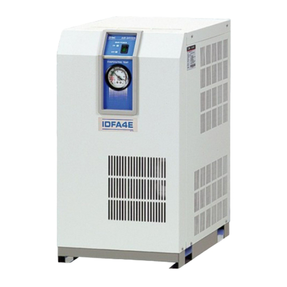
- Page 19 DOC1090580 Chapter 2 Name and Function of Parts IDFA4E to IDFA15E1 Right side Ventilation Grille (Outlet) Hot air will be exhausted from condenser by fan. No obstacles shall be allowed to place on top of it or even close the grille. Switch with lamp [ON/OFF switch] The lamp is continuously on during normal operation.
- Page 20 DOC1090580 Chapter 2 Name and Function of Parts ・No Front Panel ・No Front Panel (IDFA15E1) (IDFA4E to 11E) High pressure switch (High pressure switch appears when the front panel is removed) Refer to “6.2 Reset High Pressure Switch” for resetting. Auto Drain Do not remove the insulation on the auto drain.
-
Page 21: Chapter 3 Transportation And Installation
DOC1090580 Chapter 3 Transportation and installation Chapter 3 Transportation and installation WARNING - Use the product in an appropriate manner, and pay attention to safety, particularly physical safety of operators, during the installation, operation, maintenance and checks of the product. CAUTION - Tranportation, installation, and maintenance including dangerous work must be done by personnel who have require knowledge and experience about the product and system. -
Page 22: Installation
DOC1090580 Chapter 3 Transportation and installation Installation 3.2.1 Environment Do not use in the following environments, as it may lead to a breakdown. Potential malfunction or damage to the product may occur if these instructions are disregarded. - Avoid locations where the air dryer will be in direct contact with wind or rain. (Avoid locations where relative humidity is 85% or more) - Avoid locations where water, water vapor, salt water, or oil may splash on the product. -
Page 23: Air Piping
DOC1090580 Chapter 3 Transportation and installation 3.2.3 Air piping ⚫ Connection of the inlet and outlet of compressed air should be made removable by using union and so on. ⚫ When an air fitting is connected with the body of the product, hold the pneumatic piping at the body with a pipe wrench and tighten. -
Page 24: Drain Tube
DOC1090580 Chapter 3 Transportation and installation 3.2.4 Drain tube - A drain tube of 10mm O.D. is included as an accessory. The outlet end of the tube is released to atmosphere and lets the drain flow through the tube. (When customers prepare the drain tube, keep its length at 5m or less and the I.D. at 6.5mm or larger for correct operation of the auto drain) - Using the pressure of the compressed air, the drain will be discharged periodically. -
Page 25: Electrical Wiring
DOC1090580 Chapter 3 Transportation and installation 3.2.5 Electrical wiring WARNING - Only qualified personnel should do electrical wiring work. - Cut off the power supply for safety before the wiring. Wiring with the product energized is strictly prohibited. - Use a power supply suitable for the specifications of the product. - Supply power from a stable place, which is free from the effects of any surge. - Page 26 DOC1090580 Chapter 3 Transportation and installation Wiring procedure (1) Remove the terminal block cover or rear panel on the back of the product. (2) Connect the cable to the terminal block. (refer to the label on the terminal block) M3 Screw tightening torque : 0.5 N・m Do not touch any equipment other than the terminal block during wiring.
-
Page 27: Cautions About Reinstallation
DOC1090580 Chapter 3 Transportation and installation Cautions about Reinstallation CAUTION Only someone who has enough knowledge about the product and incidental devices should reinstall it in another place. If you move the product and reinstall it into another place after some operations (including trial running), all installation instructions in chapter 3 should be followed as well as the following instructions. - Page 28 DOC1090580 Chapter 3 Transportation and installation Cautions about Reinstallation IDFA Series...
-
Page 29: Chapter 4 Operation/ Shutdown
DOC1090580 Chapter 4 Operation/ Shutdown Chapter 4 Operation/ Shutdown CAUTION - Only someone who has enough knowledge and experience about the product and incidental devices should operate or shut down the product. Check points before operation Before trial operation, check following points. Installation state ⚫... -
Page 30: Stop
DOC1090580 Chapter 4 Operation/ Shutdown Stop 1) Turn off the switch with lamp. 2) The lamp turns off and operation stops. Depending on the condition of operation, hot air continues to be emitted from the ventilation grille by the cooling fan for a while after turning off the switch. Cautions for re-start - Allow at least 3 minutes before restarting the product. -
Page 31: Chapter 5 Checks And Maintenance
DOC1090580 Chapter 5 Checks and Maintenance Chapter 5 Checks and Maintenance WARNING - Only people who have sufficient knowledge and experience about the product and its incidental devices are allowed to perform maintenance. - Before maintenance, read and understand the important cautionary notifications in this operation manual. -
Page 32: Regular Maintenance
DOC1090580 Chapter 5 Checks and Maintenance Regular maintenance 5.2.1 Clean the dustproof filter of the ventilation grille Vacuum or air-blow the filter every month to remove dust and particles of the ventilation grille. CAUTION - Wear protective goggles or mask during air blow. 5.2.2 Auto drain maintenance Remove the dust deposited in the auto drain bowl assembly every month. -
Page 33: How To Clean And Replace The Auto Drain/Strainer
DOC1090580 Chapter 5 Checks and Maintenance 5.2.3 How to clean and replace the auto drain/strainer When carrying out maintenance work on the auto drain and auto drain strainer, please follow the steps below. (1) Removal of the bowl assembly 1) Turn off the switch with lamp. 2) Shut off the earth leakage breaker of the power supply or unplug the power plug from the socket. - Page 34 DOC1090580 Chapter 5 Checks and Maintenance (2) Mounting of the bowl assembly 1) Check the bowl packing for damage such as scratches, twisting or foreign particles attached to it. Then, apply grease thinly and fit it in the groove in the Drain separator bowl assembly.
-
Page 35: Service Parts
DOC1090580 Chapter 5 Checks and Maintenance 5.2.4 Service parts It is recommended to replace the following parts regularly. The interval values shown in this operation manual depend on the operating conditions (ambient temperature, installation environment, etc.), so that they are for reference. ・... - Page 36 DOC1090580 Chapter 5 Checks and Maintenance Regular maintenance IDFA Series...
-
Page 37: Chapter 6 Troubleshooting
DOC1090580 Chapter 6 Troubleshooting Chapter 6 Troubleshooting Troubleshooting Refer to the table below if any abnormality is found. If there is something that is not clear, please turn off the power supply and contact our service office. Problems Possible causes Action Air dryer does not Power cord is loose or not... - Page 38 DOC1090580 Chapter 6 Troubleshooting Problem Possible causes Action Evaporation Poor ventilation in installation - Keep the ambient temperature low by ventilation. thermometer location. indicates higher Ambient temperature is too high. than green zone. Ventilation grille is obstructed by a - Install so that the ventilation grill are 600mm or more wall or blocked with dust.
- Page 39 DOC1090580 Chapter 6 Troubleshooting Problem Possible causes Countermeasures Air leakage Air leaks out from the O-ring of the bowl is damaged. - Replace the bowl O-ring with a from the gap between the bowl new one. When assembling the auto drain and body.
-
Page 40: Reset High Pressure Switch
DOC1090580 Chapter 6 Troubleshooting Reset High Pressure Switch When the lamp goes off and the compressor for refrigeration stops during operation, the thermal relay or high voltage pressure switch has activated to protect the compressor for refrigeration. It is necessary to reset it manually. -
Page 41: Chapter 7 Documents
DOC1090580 Chapter 7 Documents Chapter 7 Documents Specifications 7.1.1 Specifications of IDFA3E-23-F to IDFA15E1-23-F IDFA3E IDFA4E IDFA6E IDFA8E IDFA11E IDFA15E1 Model Specification -23-F -23-F -23-F -23-F -23-F -23-F Fluid Compressed Air 5 to 50 Inlet air temperature [C] 0.15 to 1.0 Inlet air pressure [MPa] (For option K, L,V: 1.6MPa) - Page 42 DOC1090580 Chapter 7 Documents Note1: Air flow rate under the standard condition (ANR) [atmospheric pressure at 20°C, relative humidity at 65%] Note2: Air flow rate converted by the compressor intake condition [atmospheric pressure at 32°C, relative humidity at 75%]. Note3: The value is that of operation under rated condition. Note4: Install GFCI breaker that comes with sensivity of 30mA.
-
Page 43: Specifications Of Idfa6E-20-F
DOC1090580 Chapter 7 Documents 7.1.2 Specifications of IDFA6E-20-F Model IDFA6E-20-F Specification Fluid Compressed Air Inlet air temperature [C] 5 to 50 0.15 to 1.0 Inlet air pressure [MPa] (For option K, L,V: 1.6MPa) 2 to 40(Relative Humidity of 85% or less) Ambient temperature [C] Air flow rate 50Hz... -
Page 44: Coefficient Factors
DOC1090580 Chapter 7 Documents 7.1.3 Coefficient factors C Inlet air temperature ( 5 to 25 1.30 1.25 1.00 0.83 Inlet air pressure (MPa) (models:IDFA3E~11E) 0.80 0.87 0.92 0.96 1.00 1.04 1.07 1.16 1.21 1.25 Inlet air pressure (MPa) (models:IDFA15E1) 0.72 0.81 0.88... -
Page 45: Dimensions
DOC1090580 Chapter 7 Documents Dimensions • IDFA3E DRAF T AIR OUTLET AIR INLET VENT ILATIO N SWIT CH WITH LAMP AIR OUTLET EVAP ORATIO N THER MOMETE R DRAF T AIR INLET DRAI N TUBE (O.D .10 LE NGTH:0 .8m) VENT ILATIO N (820 ) TERM INAL B LOCK... - Page 46 DOC1090580 Chapter 7 Documents • IDFA15E1 SWI TCH WIT H LAM P AIR OUTL ET EVA PORAT ION THE RMOME TER AIR INLE T TER MINAL BLO CK VEN TILAT ION VEN TILAT ION 4xφ13 DRAI N TUBE (O.D .10,LE NGTH:0 .8m) POW ER SU PPLY ENTRY (φ17) GRO MMET Measure:mm...
-
Page 47: Electric Circuit
DOC1090580 Chapter 7 Documents Electric circuit ■IDFA3E-23 ■ IDFA4E-23 to IDFA11E-23 For IDFA6E,8E,11E IDFA Series 7.4 Electric circuit... - Page 48 DOC1090580 Chapter 7 Documents ■ IDFA15E1-23 ■ IDFA6E-20 Electric circuit IDFA Series...
-
Page 49: Air/ Refrigerant Circuit
DOC1090580 Chapter 7 Documents Air/ Refrigerant Circuit ・IDFA4E to 15E1 ・IDFA3E DRAIN SEPARATOR AIR INLET AIR OUTLET COOLER DRAIN OUTLET CAPILLARY TUBE REHEATER CAPACITY REGULATING NALVE HIGH PRESSURE SWITCH CONDENSER CONDENSOR PRESS. HIGH PRESSURE FAN MOTOR SWITCH SWITCH COMPRESOR EVAPORATION CONDENSER THERMOMETER Air circuit... - Page 50 DOC1090580 Chapter 7 Documents Air/ Refrigerant Circuit IDFA Series 7-10...
-
Page 51: Chapter 8 Option A
DOC1090580 Chapter 8 Option A Chapter 8 Option A For IDFA3E to 11E-23 IDFA6E-20 Safety instructions for use Refer to the instructions below when handling the product. WARNING - Shut off the power supply when removing the panel for maintenance work, etc. The product has a fan(s) and could cause serious danger to operators. - Page 52 DOC1090580 Chapter 8 Option A Air/ Refrigerant Circuit IDFA Series...
-
Page 53: Chapter 9 Option C
DOC1090580 Chapter 9 Option C Chapter 9 Option C For IDFA3E to 15E1-23 IDFA6E-20 Specifications Special epoxy resin is coated on the copper tube surface to improve the corrosion resistance the special epoxy resin is only applied where the copper tubes are not protected or insulated. Precautions for installation and handling 1) The epoxy resin minimizes the corrosion of the coated copper tubes against corrosive gas. - Page 54 DOC1090580 Chapter 9 Option C Precautions for installation and handling IDFA Series...
-
Page 55: Chapter 10 Option G
DOC1090580 Chapter 10 Option G Chapter 10 Option G For IDFA3E to 15E1-23 IDFA6E-20 10.1 Specifications Outside panel has Chinese name plate and Chinese operation manual IDFA Series 10.1 Specifications 10-3... - Page 56 DOC1090580 Chapter 10 Option G Specifications 10.1 IDFA Series 10-4...
-
Page 57: Chapter 11 Option H
DOC1090580 Chapter 11 Option H Chapter 11 Option H For IDFA6E-20 When handling the product, take care to the following precautions. Warning - Do not remove the auto drain with the air pressure remaining internally. If the compressed air is left in the product, when some part is loosened, it may cause sudden lurching or other unexpected accidents. - Page 58 DOC1090580 Chapter 11 Option H ・Table 11-1 Auto drain product number for replacement Product number Product name Remarks Bowl assembly IDF-S1941 ― thermal insulator AD48-2-A Bowl assembly With bowl packing This bowl assembly product number only applies for products manufactured after March 2019. ・Table 11-2 Auto drain Parts Product name Product number...
-
Page 59: Chapter 12 Option K
DOC1090580 Chapter 12 Option K Chapter 12 Option K For IDFA6E to 15E1-23 12.1 Safety instructions IDFA6E-20 When handling the product, take care of the following precautions. WARNING 1. Do not remove the auto drain if air pressure remains in the product. When removing the auto drain, stop the supply of air to the primary side of the product, exhaust the air from the secondary side and ensure there is no residual pressure. - Page 60 DOC1090580 Chapter 12 Option K ・Table 12-1 Auto drain product number for replacement Product number Product name Remarks Bowl assembly IDF-S1926 1 ― thermal insulator AD48-8-A-X2112 Bowl assembly 1 With bowl packing This bowl assembly product number only applies for products manufactured after March 2019. ・Table 12-2 Auto drain Parts Product number Product name...
-
Page 61: Chapter 13 Option L
DOC1090580 Chapter 13 Option L Chapter 13 Option L For IDFA4E to 15E1-23 IDFA6E-20 Option L: Dryer with heavy duty auto drain. The heavy duty auto drain to be assembled by customer. 13.1 Safety instructions for use Refer to the instructions below when handling the product. WARNING 1. -
Page 62: Specification Of Heavy Duty Auto Drain (Adh4000-04)
DOC1090580 Chapter 13 Option L 13.3 Specification of heavy duty auto drain (ADH4000-04). Heavy duty Heavy duty auto drain ADH4000-04 Auto drain Part number Replacement kit for ADH4000-04 (Service parts) exhaust valve ADH-E400 mechanism Replacement kit Auto drain type Float type for exhaust valve mechanism Auto drain valve type... -
Page 63: Chapter 14 Option R
DOC1090580 Chapter 14 Option R Chapter 14 Option R For IDFA4E to 15E1-23 IDFA6E-20 R installs a Ground Fault Circuit Interrupter (GFCI), it will shut off the power supply in Option case the product should have over current or current leakage. Additionally, the power supply should be connected directly to the primary side of the GFCI. -
Page 64: Specifications Of The Gfci
DOC1090580 Chapter 14 Option R 14.2 Specifications of the GFCI Specifications of GFCI Dryer model number SCCR [kA] Rated current [A] Current sensitivity [mA] IDFA4E/6E/8E/11E-23-*FR* IDFA6E-20-*FR* IDFA15E1-23-*FR* 14.3 How to connect the power supply Connect the power supply cable in the following procedure. 1) Take off the rear panel. -
Page 65: Chapter 15 Option T
DOC1090580 Chapter 15 Option T Chapter 15 Option T For IDFA4E to 15E1-23 IDFA6E-20 Option T has terminal block for the output of operation and error signals and remote control. 15.1 Safety instructions for use Refer to the instructions below when handling the product. WARNING All electrical work must be carried out in a safe manner by a qualified person in compliance with applicable national regulations. -
Page 66: How To Connect The Power Supply And Signal Cable
DOC1090580 Chapter 15 Option T 15.3 How to connect the power supply and signal cable Connect the power cable and signal cable in the following procedures. 1) Take off the rear panel. 2) Insert the power cable prepared by the customer into the power cable inlet (with rubber grommet) and bring the power cable near the terminal block through the base hole. -
Page 67: Electric Circuit
DOC1090580 Chapter 15 Option T 15.4 Electric circuit ■IDFA4E-23-*FT* to IDFA11E-23-*FT* For IDFA6E,8E,11E ■IDFA15E1-23-*FT* IDFA Series 15.4 Electric circuit 15-3... - Page 68 DOC1090580 Chapter 15 Option T ■IDFA6E-20-*FT* Electric circuit 15.4 IDFA Series 15-4...
-
Page 69: Chapter 16 Option V
DOC1090580 Chapter 16 Option V Chapter 16 Option V For IDFA4E to 15E1-23 IDFA6E-20 Option V is a dryer with a timer controlled solenoid valve type auto drain. The timer is adjusted by customer according to the operating conditions. 16.1 Safety instructions for use When handling the product, take care of the following precautions. -
Page 70: Maintenance
DOC1090580 Chapter 16 Option V 16.3 Maintenance Be sure to perform regular maintenance of the strainer. Follow the following steps to perform maintenance. 1) Close the ball valve. 2) Press the test switch to release the residual pressure. 3) Remove the strainer and clean it. 4) Mount the strainer and open the ball valve. -
Page 71: Chapter 17 Inspection Record
DOC1090580 Chapter 17 Inspection record Chapter 17 Inspection record 17.1 Inspection record We recommend keeping the inspection record for maintenance or service. Product No. Description Contents of check Date IDFA Series 17.1 Inspection record 17-3... - Page 72 Revision history Tel: + 81 3 5207 8249 Fax: +81 3 5298 5362 https://www.smcworld.com Note: Specifications are subject to change without prior notice and any obligation on the part of the manufacturer. © SMC Corporation All Rights Reserved...
Need help?
Do you have a question about the IDFA3E-23-F and is the answer not in the manual?
Questions and answers