Table of Contents
Advertisement
Quick Links
Foreword ----------------------------------------------------------- 0-1
Emission-related components warranty
(USA and CANADA only) --------------------------------- 0-1-1
Before servicing this machine --------------------------- 0-2
EC regulation approved ------------------------------------ 0-3
Table to enter S/No and distribution --------------------- 0-4
Safety labels ------------------------------------------------------ 0-5
Machine data plate -------------------------------------------- 0-22
Guide (direction, S/No, symbol) ------------------------ 0-23
1. Before operating the machine -------------------- 1-1
2. During operating the machine -------------------- 1-16
3. During maintenance ----------------------------------- 1-23
4. Parking -------------------------------------------------------- 1-26
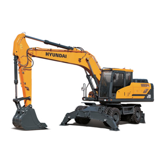
1. Major components ------------------------------------- 2-1
2. Specifications -------------------------------------------- 2-2
3. Working range ------------------------------------------- 2-4
4. Weight ------------------------------------------------------- 2-6
5. Lifting capacities ---------------------------------------- 2-7
6. Bucket selection guide ------------------------------- 2-20
7. Specification for major components ----------- 2-22
8. Recommended oils ------------------------------------ 2-26
1. Cab devices ----------------------------------------------- 3-1
2. Cluster ------------------------------------------------------- 3-2
3. Switches ---------------------------------------------------- 3-40
4. Levers and pedals ------------------------------------- 3-48
5. Others -------------------------------------------------------- 3-52
1. Suggestion for new machine ---------------------- 4-1
2. Check before starting the engine --------------- 4-2
3. Starting and stop the engine ---------------------- 4-3
4. Mode selection system ------------------------------ 4-7
5. Operation of the working device ----------------- 4-12
6. Traveling of the machine ---------------------------- 4-13
7. Efficient working method --------------------------- 4-19
8. Operation in the special work sites ------------ 4-24
9. Normal operation of excavator ------------------- 4-26
10. Attachment lowering ---------------------------------- 4-27
11. Storage ------------------------------------------------------- 4-28
12. RCV lever operating pattern ----------------------- 4-30
13. SCR system cleaning --------------------------------- 4-32
1. Road traveling -------------------------------------------- 5-1
2. Preparation for transportation -------------------- 5-2
3. Dimension and weight ------------------------------- 5-3
4. Loading the machine --------------------------------- 5-5
5. Fixing the machine ------------------------------------ 5-7
6. Loading and unloading by crane --------------- 5-8
1. Instruction -------------------------------------------------- 6-1
2. Tightening torque --------------------------------------- 6-6
3. Fuel, coolant and lubricants ----------------------- 6-9
4. Maintenance check list ------------------------------ 6-11
5. Maintenance chart ------------------------------------- 6-16
6. Service instruction ------------------------------------- 6-18
7. Electrical system ---------------------------------------- 6-48
8. Air conditioner and heater -------------------------- 6-51
1. Engine -------------------------------------------------------- 7-1
2. Electrical system ---------------------------------------- 7-2
3. Others --------------------------------------------------------- 7-3
1. Selecting hydraulic breaker ----------------------- 8-1
2. Circuit configuration ----------------------------------- 8-2
3. Maintenance ---------------------------------------------- 8-3
5. Quick clamp ----------------------------------------------- 8-6
------------------------------------------------------------- 9-1
CONTENTS
CONTENTS
Advertisement
Table of Contents

Related Manuals for Hyundai HW210


Summary of Contents for Hyundai HW210
-
Page 1: Table Of Contents
CONTENTS CONTENTS Foreword ----------------------------------------------------------- 0-1 7. Efficient working method --------------------------- 4-19 Emission-related components warranty 8. Operation in the special work sites ------------ 4-24 (USA and CANADA only) --------------------------------- 0-1-1 9. Normal operation of excavator ------------------- 4-26 Before servicing this machine --------------------------- 0-2 10. -
Page 2: Foreword
3. Use genuine HD Hyundai Construction Equipment spare parts genuine HD Hyundai Construction Equipment spare parts for the replacement of parts. We expressly point out that HD Hyundai Construction Equipment will not accept any responsibility for defects resulting from non-genuine parts or non workmanlike repair. - Page 3 Naturally, this warranty does not cover to damage arising from accident, misuse or negligence, use of non-HD Hyundai Construction Equipment parts, or from alterations not authorized by HD Hyundai Construction Equipment. ※ Emission-related components according to the EPA regulation.
-
Page 4: Before Servicing This Machine
The procedures in this manual do not supersede any requirements imposed by federal, state, provin- cial or local laws. HD Hyundai Construction Equipment can not anticipate every possible circumstance or environment in which this machine may be used and serviced. -
Page 5: Ec Regulation Approved
EC REGULATION APPROVED EC REGULATION APPROVED · Noise level (EN474-1 : 2006 and 2000/14/EC) are as followings. : 102dB (EU only) 71dB · The value of vibrations transmitted by the operator's seat are lower than standard value of (EN474-1 : 2006 and 2002/44/EC) - Page 6 477 Bundangsuseo-ro, Bundang-gu, Seongnam-si, Gyeonggi-do 13553, Korea HD Hyundai Construction Equipment Europe N.V located at Hyundailaan 4, 3980 Tessenderlo, Belgium, as authorized representative in the European Community is authorized to compile the technical construction file and declares that the product:...
- Page 7 Address Seongnam-si, Gyeonggi-do 13553, Korea HD Hyundai Construction Equipment Americas, Inc Distributor for U.S.A 6100 Atlantic Boulevard Norcross Address GA 30071 U.S.A Distributor for Europe HD Hyundai Construction Equipment Europe N. V. Hyundailaan 4 Address 3980 Tessenderlo Belgium Dealer Address...
-
Page 8: Safety Labels
SAFETY LABELS SAFETY LABELS 1. LOCATION 1. LOCATION Always keep these labels clean. If they are lost or damage, attach them again or replace them with a new label. 50 39 LH(3EA), RH(1EA) BATTERY COVER 22 53 91N6-01111 (2 PATTERN) RH EXHAUST COVER LH CONSOLE BOX 91N6-01102... -
Page 9: Air Cleaner Filter
2. DESCRIPTION 2. DESCRIPTION There are several specific warning labels on this machine please become familiarized with all warn- ing labels. Replace any safety label that is damaged, or missing. If a safety label is attached to a part that is replaced, install a safety label on the replacement part. - Page 10 4) 4) FUELING FUELING (item 4) This warning label is positioned on the vicinity of fuel filler neck. Stop the engine when refueling. All Stop the engine when refueling. All lights or flames shall be kept at a safe lights or flames shall be kept at a safe distance while refueling.
-
Page 11: High Pressure Hose
6) 6) HIGH PRESSURE HOSE HIGH PRESSURE HOSE (item 6) This warning label is positioned on the right side of the hydraulic tank. Escaping fluid under pressure can pene- Escaping fluid under pressure can pene- trate the skin causing serious injury. trate the skin causing serious injury. -
Page 12: Lifting Eye
LIFTING EYE LIFTING EYE (item 10) This warning label is positioned on the counterweight. Do not lift the machine by using lifting Do not lift the machine by using lifting eyes on the counterweight or the lifting eyes on the counterweight or the lifting eyes may be subject to overload causing eyes may be subject to overload causing its breaking and possible personal injury. - Page 13 SHEARING-ENGINE HOOD SHEARING-ENGINE HOOD (item 15) This warning label is positioned on the engine hood. Do not open the engine hood during the Do not open the engine hood during the engine's running. Stay clear of rotating engine's running. Stay clear of rotating parts.
- Page 14 REF OPERATOR'S MANUAL REF OPERATOR'S MANUAL (item 20) This warning label is positioned on the right side window of the cab. (1) (1) Ref operator manual Ref operator manual Study the operator's manual before start- Study the operator's manual before start- ing and operating machine.
-
Page 15: Air Conditioner Filter
19 19) SAFETY REAR WINDOW SAFETY REAR WINDOW (item 23) This warning label is positioned on the inside of rear window. ※ The rear window serves us an alternate The rear window serves us an alternate exit. exit. ※ To remove rear window, pull the ring and To remove rear window, pull the ring and push out the glass. -
Page 16: Electric Welding
CLAMP LOCKING CLAMP LOCKING (item 32) This warning label is positioned on the right side window of cab. Serious injury or death can result from Serious injury or death can result from dropping bucket. dropping bucket. Operating the machine with quick clamp Operating the machine with quick clamp switch unlocked or without safety pin of switch unlocked or without safety pin of... - Page 17 FALLING FALLING (item 39) This warning label is positioned on the top of the counterweight and pump hood. Falling is one of the major cause of per- Falling is one of the major cause of per- sonal injury. sonal injury. Be careful of slippery conditions on the Be careful of slippery conditions on the platforms, steps and handrails when...
- Page 18 A special air bleed valve is nec- mulator. A special air bleed valve is nec- essary for this operation, so please con- essary for this operation, so please con- tact your HD Hyundai Construction tact your HD Hyundai Construction Equipment distributor. Equipment distributor.
- Page 19 M A C H I N E C O N T R O L PAT T E R N M A C H I N E C O N T R O L PAT T E R N CHANGE-W/VALVE CHANGE-W/VALVE (item 46) This warning label is positioned on the LH rear support of cowl.
- Page 20 LUBRICATION OIL LUBRICATION OIL (item 49) This warning label is positioned on the right side of the hydraulic tank. ※ Recommended lubrication oil ACEA-E9 Recommended lubrication oil ACEA-E9 is equivalent to API CJ-4. is equivalent to API CJ-4. ※ See page 6-9 for details. See page 6-9 for details.
- Page 21 DOZER/OUTRIGGER IDEOGRAM DOZER/OUTRIGGER IDEOGRAM (item 54) This warning label is positioned on the LH console box. ※ See page 4-12 for details. See page 4-12 for details. ※ Guidlines for using the general dozer Guidlines for using the general dozer blade.
- Page 22 KEY OFF CAUTION KEY OFF CAUTION (item 57) This warning label is positioned on the right side window of the cab. ※ Park on a flat place and stop the engine Park on a flat place and stop the engine for inspecting and repairing.
- Page 23 DEF/AdBlue® DEF/AdBlue® FILL-UP FILL-UP (item 60) This warning label is positioned on the front WA R N I N G of DEF/AdBlue® tank. VERY IMPORTANT Be careful not to entering dust, sand or Be careful not to entering dust, sand or BE CAREFUL NOT TO ENTERING DUST, SAND OR OTHER CONTAMINATION SUBSTANCES WHEN YOU REFILL THE other contamination substances when you...
- Page 24 REFRIGERANT REFRIGERANT (item 63) This warning label is positioned on the right side of engine hood. Inhaling air conditioner refrigerant gas Inhaling air conditioner refrigerant gas through a lit cigarette or other smoking through a lit cigarette or other smoking method or inhaling fumes released from method or inhaling fumes released from a flame contacting air conditioner refrig-...
-
Page 25: Machine Data Plate
The machine serial number assigned to this particular machine and should be used when request- ing information or ordering service parts for this machine from your authorized HD Hyundai Construction Equipment dealer. The machine serial number is also stamped on the frame. -
Page 26: Guide (Direction, S/No, Symbol)
GUIDE GUIDE 1. DIRECTION 1. DIRECTION Forward The direction of this manual indicate forward, back- ward, right and left on the standard of operator when the dozer blade is in the rear and machine is on the traveling direction. Left Right Backward 210WF0SG01... -
Page 27: Safety Hints
SAFETY HINTS SAFETY HINTS 1. BEFORE OPERATING THE MACHINE 1. BEFORE OPERATING THE MACHINE Think-safety first. In special situation, wear protective clothing including a safety helmet, safety shoes, gloves, safety glasses and ear protection as required by the job condition. Almost every accident is caused by disregard- ing the simple and fundamental safety hints. - Page 28 Check daily according to the operation manual. Repair the damaged parts and tighten the loos- ened bolts. 17W31SH05 Check for leakage of engine oil, hydraulic oil, fuel and coolant. Keep machine clean, clean machine regularly. 17W31SH06 Do not operate the machine if it requires repairs. Operate after complete repair.
-
Page 29: Unauthorized Modification
HD Hyundai Construction Equipment can create hazards. Before making a modification, consult your HD Hyundai Construction Equipment distributor. HD Hyundai Construction Equipment will not be respon-sible for any injury or damage caused by any unauthorized modification. PREPARE FOR EMERGENCY... - Page 30 Do not use attachments that are not authorized by HD Hyundai Construction Equipment or your HD Hyundai Construction Equipment distributor. Use of unauthorized attachments could create a safety problem and adversely affect the proper operation and useful life of the machine.
-
Page 31: Safety Features
SAFETY FEATURES SAFETY FEATURES Be sure all guards and covers are in their prop- er position. Have guards and covers repaired if damaged. Use safety features such as safety lock and seat belts properly. Never Never remove any safety features. Always Always keep them in good operating condition. - Page 32 FIRE PREVENTION AND EXPLOSION PREVENTION FIRE PREVENTION AND EXPLOSION PREVENTION Regeneration Regeneration The exhaust gas temperatures during regeneration will be elevated. Follow proper fire prevention instructions and use the disable regeneration function when appropriate. General General All fuels, most lubricants, and some coolant mixtures are flammable.
- Page 33 Store fuels and lubricants in properly marked containers away from unauthorized personnel. Store oily rags and flammable materials in protective containers. Do not smoke in areas that are used for storing flammable materials. 3001SH02 Use caution when you are fueling a machine. Do not smoke while you are fueling a machine.
- Page 34 Replace cables and related parts that show signs of wear or damage. Contact your HD Hyundai Construction Equipment dealer. show signs of wear or damage. Contact your HD Hyundai Construction Equipment dealer.
- Page 35 Do not operate a machine when a fire hazard exists. Repair any lines that are corroded, loose, or damaged. Leaks may provide fuel for fires. Consult your HD Hyundai Construction Equipment dealer for repair or for replacement parts.
- Page 36 Fire Extinguisher ire Extinguisher As an additional safety measure, keep a fire extinguisher on the machine. Be familiar with the operation of the fire extinguisher. Inspect the fire extinguisher and service the fire extinguisher regularly. Follow the recommendations on the instruction plate. Consider installation of an aftermarket Fire Suppression System, if the application and working conditions warrant the installation.
- Page 37 Do not weld the ROPS structure in order to install the fire extinguisher. Also, do not drill holes in the ROPS structure in order to mount the fire extinguisher on the ROPS. Consult your HD Hyundai Construction Equipment dealer for the proper procedure for mounting the fire extinguisher.
- Page 38 THE EUROPEAN UNION PHYSICAL AGENTS (VIBRATION) DIRECTIVE 2002/44/EC THE EUROPEAN UNION PHYSICAL AGENTS (VIBRATION) DIRECTIVE 2002/44/EC Vibration Data for Earth-moving Machines ibration Data for Earth-moving Machines Information Concerning Hand/Arm Vibration Level nformation Concerning Hand/Arm Vibration Level When the machine is operated according to the intended use, the hand/arm vibration of this machine is below 2.5 m/s Information Concerning Whole Body Vibration Level nformation Concerning Whole Body Vibration Level...
- Page 39 ※ All vibration levels are in meter per second squared. All vibration levels are in meter per second squared. ISO Reference Table A – Equivalent vibration levels of whole body vibration emission for earthmoving equipment. Vibration Levels Scenario Factors Machine Typical operating Machine kind family...
- Page 40 Guidelines for Reducing Vibration Levels on Earthmoving Equipment uidelines for Reducing Vibration Levels on Earthmoving Equipment Properly adjust machines. Properly maintain machines. Operate machines smoothly. Maintain the conditions of the terrain. The following guidelines can help reduce the whole body vibration level : Use the right type and size of machine, equipment, and attachments.
- Page 41 Modifications may be considered to be officially approved, if at least one of the following conditions has been met : 1. The attachment, the accessory, or the spare part has been made or distributed by HD Hyundai Construction Equipment and has been installed according to approved methods described in a publication available from HD Hyundai Construction Equipment;...
-
Page 42: During Operating The Machine
2. DURING OPERATING THE MACHINE 2. DURING OPERATING THE MACHINE Use the handle and footstep when getting on or off the machine. Do not jump on or off the machine. 17W31SH09 Sound the horn to warn nearby personnel before operating the machine. Remove all the obstacles like frost on the win- dow before operating the machine for the good visibility. - Page 43 Provide proper ventilation when operating engine in a closed area to avoid the danger of exhaust gases. 17W31SH13 Check the locations of underground gas pipes or water line and secure the safety before oper- ation. 17W31SH14 The operating near the electrical lines is very dangerous.
- Page 44 Watch out for obstacles. Be particularly careful to check the machine clearance during the swing. 17W31SH17 When using the machine as breaker or working in a place where stones may fall down, cab roof guard and head guard should be provided for proper protection.
- Page 45 Avoid traveling in a cross direction on a slope as it can cause the danger of rolling over and slid- ing. 17W31SH21 Traveling on a slope is dangerous. Be sure to operate slowly when traveling down a slope and maintain the bucket at a height of 20~30 cm (1 ft) above the ground so that it can be used as brake in an emergency.
- Page 46 The operation on a slope is dangerous. Avoid operating the machine on a slope of over 10 degree. 17W31SH25 Operate the machine after making ground flat when operation is required on a slope. 17W31SH26 The swing on the slope can be danger of rolling over.
- Page 47 Before traveling the machine, sound the horn to warn nearby personnel. Operate forward and backward correctly with confirming the location of the travel motor. 17W31SH29 Slow down when traveling through obstacles or uneven ground. 17W31SH30 When operating in water or when crossing shal- low, check the bed soil condition and depth and flow speed of water, then proceed taking care that water is not above axle center.
-
Page 48: Mounting And Dismounting
When mounting or dismounting, always face the machine and use the handrails, machine or foot steps. In this case please contact your HD Hyundai Construction Equipment distributor. Do not hold any control levers when getting on or off the machine. -
Page 49: During Maintenance
3. DURING MAINTENANCE 3. DURING MAINTENANCE Stop the engine immediately when the trouble of the machine is found. Inspect immediately the cause of trouble such as vibration, overheating and trouble in the clus- ter then repair. 17W31SH32 Park on a flat place and stop the engine for inspecting and repairing. - Page 50 There is the danger of fire in fuel and oil. Store in cool and dry area, away from any open flames. 17W31SH36 Do not touch exhaust pipe, or may cause severe burn. 17W31SH37 Do not open the engine hood and covers while the engine is running.
- Page 51 Be careful that the front window may be promptly closed. Be sure to support stay, when the side door needs to be opened. Be careful that the open side door may closed by the external or natural force like strong wind. 17W31SH40 The antislip protection should be replaced if they have become worn or have been printed...
-
Page 52: Parking
4. PARKING 4. PARKING When leaving the machine after parking, lower the bucket to the ground completely and put the safety knob at the LOCK position then remove the key. Lock the cab door. 17W31SH43 Park the machine in the flat and safe place. 17W31SH44 Hope you can work easily and safely observing safety rules. -
Page 53: Specifications
SPECIFICATIONS SPECIFICATIONS 1. MAJOR COMPONENTS 1. MAJOR COMPONENTS Bucket Tooth Tool box DEF/AdBlue tank Fuel tank Hydraulic tank Main pump After treatment device Engine Charge air cooler Oil cooler Radiator Battery Outrigger Tire Turning joint Swing motor Main control valve Arm cylinder Boom Boom cylinder... -
Page 54: Specifications
2. SPECIFICATIONS 2. SPECIFICATIONS 1) 1) 5.65 5.65 m (18' 6") MONO BOOM, 2.92 (18' 6") MONO BOOM, 2.92 m (9' 7") ARM, FRONT OUTRIGGER AND REAR (9' 7") ARM, FRONT OUTRIGGER AND REAR DOZER BLADE DOZER BLADE Travel position I(I') B(L) 210WF2SP02... -
Page 55: Dozer Blade
2) 2) 5.39 5.39 m (17' 8") (17' 8") 2-PIECE 2-PIECE BOOM, 2.4 m (7' 10") ARM, FRONT OUTRIGGER AND REAR BOOM, 2.4 m (7' 10") ARM, FRONT OUTRIGGER AND REAR DOZER BLADE DOZER BLADE Travel position I(I') B(L) 210WF2SP03 Description Unit Specification... -
Page 56: Working Range
3. WORKING RANGE 3. WORKING RANGE 1) 1) 5.65 5.65 m (18' 6") MONO BOOM (18' 6") MONO BOOM 210WF2SP04 Description 2.0 m (6' 7") Arm 2.92 m (9' 7") Arm 2.40 m (7' 10") Arm Max digging reach 9110 mm (29'11") 9480 mm (31' 1") 9960 mm... - Page 57 2) 2) 5.39 5.39 m (17' 8") (17' 8") 2-PIECE 2-PIECE BOOM BOOM 210WF2SP05 Description 2.0 m (6' 7") Arm 2.92 m (9' 7") Arm 2.40 m (7' 10") Arm Max digging reach 8890 mm (29' 2") 9290 mm (30' 6") 9800 mm (32' 2") Max digging reach on ground...
-
Page 58: Weight
4. WEIGHT 4. WEIGHT Item Upperstructure assembly 8950 19730 Main frame weld assembly 1760 3880 Engine assembly 1150 Main pump assembly Main control valve assembly Swing motor assembly Hydraulic oil tank weld assembly Fuel tank weld assembly Counterweight 3400 7500 Cab assembly 1100 Lower frame weld assembly... -
Page 59: Lifting Capacities
The difference between the weight of a work tool attachment must be subtracted. The difference between the weight of a work tool attachment must be subtracted. Consult your HD Hyundai Construction Equipment dealer regarding the lifting capacities for Consult your HD Hyundai Construction Equipment dealer regarding the lifting capacities for specific work tools and attachments. - Page 60 5.65 m (18' 6") boom, 2.00 m (6' 7") arm equipped with 0.80 m (SAE heaped) bucket and 4 out- rigger up. Load radius At max. reach 3.0 m (10 ft) 4.5 m (15 ft) 6.0 m (20 ft) 7.5 m (25 ft) Capacity Reach Load point...
- Page 61 5.65 m (18' 6") boom, 2.00 m (6' 7") arm equipped with 0.80 m (SAE heaped) bucket, outrigger up and dozer blade up. Load radius At max. reach 3.0 m (10 ft) 4.5 m (15 ft) 6.0 m (20 ft) 7.5 m (25 ft) Capacity Reach...
- Page 62 5.65 m (18' 6") boom, 2.40 m (7' 10") arm equipped with 0.80 m (SAE heaped) bucket, 4-outrig- ger up. Load radius At max. reach 1.5 m (5 ft) 3.0 m (10 ft) 4.5 m (15 ft) 6.0 m (20 ft) 7.5 m (25 ft) Capacity Reach...
- Page 63 5.65 m (18' 6") boom, 2.40 m (7' 10") arm equipped with 0.80 m (SAE heaped) bucket, outrigger up and dozer blade up. Load radius At max. reach 1.5 m (5 ft) 3.0 m (10 ft) 4.5 m (15 ft) 6.0 m (20 ft) 7.5 m (25 ft) Capacity...
- Page 64 (10) 5.65 m (18' 6") boom, 2.92 m (9' 7") arm equipped with 0.80 m (SAE heaped) bucket, 4-outrigger Load radius At max. reach 1.5 m (5 ft) 3.0 m (10 ft) 4.5 m (15 ft) 6.0 m (20 ft) 7.5 m (25 ft) Capacity Reach...
- Page 65 (12) 5.65 m (18' 6") boom, 2.92 m (9' 7") arm equipped with 0.80 m (SAE heaped) bucket, outrigger up and dozer blade up. Load radius At max. reach 1.5 m (5 ft) 3.0 m (10 ft) 4.5 m (15 ft) 6.0 m (20 ft) 7.5 m (25 ft) Capacity...
- Page 66 2) 2) ADJUST ADJUST BOOM BOOM 5.39 m (17' 8") boom, 2.00 m (6' 7") arm equipped with 0.80 m (SAE heaped) bucket, 4-outrigger down. Load radius At max. reach Load point 3.0 m (10 ft) 4.5 m (15 ft) 6.0 m (20 ft) 7.5 m (25 ft) Capacity...
- Page 67 5.39 m (17' 8") boom, 2.00 m (6' 7") arm equipped with 0.80 m (SAE heaped) bucket, outrigger down and dozer blade down. Load radius At max. reach 3.0 m (10 ft) 4.5 m (15 ft) 6.0 m (20 ft) 7.5 m (25 ft) Capacity Reach...
- Page 68 5.39 m (17' 8") boom, 2.40 m (7' 10") arm equipped with 0.80 m (SAE heaped) bucket, 4-outrig- ger down. Load radius At max. reach 3.0 m (10 ft) 4.5 m (15 ft) 6.0 m (20 ft) 7.5 m (25 ft) Capacity Reach Load point...
- Page 69 5.39 m (17' 8") boom, 2.40 m (7' 10") arm equipped with 0.80 m (SAE heaped) bucket, outrigger down and dozer blade down. Load radius At max. reach 3.0 m (10 ft) 4.5 m (15 ft) 6.0 m (20 ft) 7.5 m (25 ft) Capacity Reach...
- Page 70 5.39 m (17' 8") boom, 2.92 m (9' 7") arm equipped with 0.80 m (SAE heaped) bucket, 4-outrigger down. Load radius At max. reach 3.0 m (10 ft) 4.5 m (15 ft) 6.0 m (20 ft) 7.5 m (25 ft) Capacity Reach Load point...
- Page 71 (11) 5.39 m (17' 8") boom, 2.92 m (9' 7") arm equipped with 0.80 m (SAE heaped) bucket, outrigger down and dozer blade down. Load radius At max. reach 3.0 m (10 ft) 4.5 m (15 ft) 6.0 m (20 ft) 7.5 m (25 ft) Capacity Reach...
-
Page 72: Bucket Selection Guide
Select an optimum combination according to the working conditions and the type of work that is being done. is being done. Consult your HD Hyundai Construction Equipment dealer for information on selecting the cor- Consult your HD Hyundai Construction Equipment dealer for information on selecting the cor- rect boom-arm-bucket combination. - Page 73 2) 2) HEAVY DUTY AND ROCK-HEAVY DUTY BUCKET HEAVY DUTY AND ROCK-HEAVY DUTY BUCKET ◈ 0.90, 1.05 m ◆ ◆ 0.87 m heaped bucket heaped bucket Recommendation Capacity Width 5.65 m (18' 6") boom 5.39 m (17' 8") adjust boom Weight Without With...
-
Page 74: Specification For Major Components
7. SPECIFICATIONS FOR MAJOR COMPONENTS 7. SPECIFICATIONS FOR MAJOR COMPONENTS 1) 1) ENGINE ENGINE Item Specification Model Cummins QSB6.7 Type 4-cycle turbocharged charger air cooled diesel engine Cooling method Water cooling Number of cylinders and arrangement 6 cylinders, in-line Firing order 1-5-3-6-2-4 Combustion chamber type Direct injection type... -
Page 75: Main Control Valve
3) 3) GEAR PUMP GEAR PUMP Item Specification Type Fixed displacement gear pump single stage Capacity 15cc/rev Maximum pressure 40 kgf/cm (570 psi) Rated oil flow 25.5ℓ/min (6.7 U.S. gpm/5.6 U.K. gpm) 4) 4) MAIN CONTROL VALVE MAIN CONTROL VALVE Item Specification Type... -
Page 76: Power Train
7) 7) POWER TRAIN POWER TRAIN Item Description Specification Type 2 speed power shift transmission 4.87 Transmission Gear ratio 1.20 Clutch pressure 30~32 kgf /cm (427~455 psi) Type Multi disc brake integrated in transmission Parking brake Maximum braking torque 2937 kgf·m (21240 lbf·ft) Type 4 wheel drive with differential Gear ratio... - Page 77 CYLINDER CYLINDER Item Specification Ø120×Ø85×1290 mm Bore dia×Rod dia×Stroke Boom cylinder Cushion Extend only Ø140×Ø100×1510 mm Bore dia×Rod dia×Stroke Arm cylinder Cushion Extend and retract Ø125×Ø85×1055 mm Bore dia×Rod dia×Stroke Bucket cylinder Cushion Extend only Ø125×Ø75×222 mm Bore dia×Rod dia×Stroke Dozer cylinder Cushion Extend only...
-
Page 78: Recommended Oils
※ Do not mix HD Hyundai Construction Equipment genuine oil with any other lubricating oil as it may result in Do not mix HD Hyundai Construction Equipment genuine oil with any other lubricating oil as it may result in damage to the systems of major components. -
Page 79: Control Devices
CONTROL DEVICES CONTROL DEVICES 1. CAB DEVICES 1. CAB DEVICES The ergonomically designed console box and suspension type seat provide the operator with com- fort. 2) 2) ELECTRONIC MONITOR SYSTEM ELECTRONIC MONITOR SYSTEM The centralized electronic monitor system allows the status and conditions of the machine to be monitored at a glance. -
Page 80: Cluster
2. CLUSTER 2. CLUSTER 1) 1) STRUCTURE STRUCTURE The cluster consists of LCD and switches as shown below. The LCD is to warn the operator in case of abnormal machine operation or conditions for the appropriate operation and inspection. Also, The LCD is to set and display for modes, monitoring and utilities with the switches. The switches or touch screen are to set the machine operation modes. - Page 81 2) 2) GAUGE GAUGE (1) (1) Operation screen Operation screen When you first turn starting switch ON, the operation screen will appear. Default Option 210WF3CD51K RPM / Speed gauge DEF/AdBlue® level gauge Engine coolant temperature gauge Tripmeter display Hydraulic oil temperature gauge Eco guage Fuel level gauge Accel dial gauge...
- Page 82 (4) (4) Hydraulic oil temperature gauge Hydraulic oil temperature gauge ① This gauge indicates the temperature of hydraulic oil. ·White range : 40-105˚C(104-221˚F) ·Red range : Above 105˚C(221˚F) ② If the indicator is in the red range or lamp pops up and the buzzer sounds reduce the load on the system.
- Page 83 (8) (8) Eco gauge Eco gauge ① This gauge indicates the fuel consumption rate and machine load status. So that operators can be careful with fuel econo- ② The fuel consumption rate or machine load is higher, the number of segment is increased. ③...
-
Page 84: Warning Lamps
3) 3) WARNING LAMPS WARNING LAMPS Engine oil filter warning lamp Battery charging warning lamp Air cleaner warning lamp Check engine warning lamp Overload warning lamp Engine oil pressure warning lamp Brake fail warning lamp Engine coolant low level warning lamp T/M oil pressure warning lamp Emergency warning lamp Engine stop warning lamp... - Page 85 (1) (1) Engine coolant temperature warning lamp Engine coolant temperature warning lamp ① Engine coolant temperature warning is indicated two steps. 103˚C over : The lamp pops up and the buzzer sounds. 107˚C over : The lamp pops up and the buzzer sounds. ②...
- Page 86 ※ Refer to page 3-10. Refer to page 3-10. ※ Please contact your Please contact your HD Hyundai Construction Equipment HD Hyundai Construction Equipment service center or local dealer. service center or local dealer. (9) (9) Battery charging warning lamp Battery charging warning lamp ①...
- Page 87 (10) (10) Air cleaner warning lamp Air cleaner warning lamp ① This warning lamp pops up and the buzzer sounds when the filter of air cleaner is clogged. ② Check the filter and clean or replace it. 290F3CD68 (11) (11) Water in fuel warning lamp Water in fuel warning lamp ①...
- Page 88 These lamps will be ON when a stationary (manual) SCR sys- tem cleaning is not performed. · Stop the engine immediately. · Please contact your HD Hyundai Construction Equipment ser- vice center or local dealer. (14) (14) SCR system cleaning...
- Page 89 ※ Manual SCR system cleaning Manual SCR system cleaning ※ Manual SCR system cleaning applies if the machine is in a Manual SCR system cleaning applies if the machine is in a fireproof area. fireproof area. ※ To stop a manual SCR system cleaning before it has com- To stop a manual SCR system cleaning before it has com- pleted, set to the SCR system cleaning switch to the inhibit pleted, set to the SCR system cleaning switch to the inhibit...
- Page 90 (16) (16) DEF/AdBlue® level warning lamp DEF/AdBlue® level warning lamp ① This warning lamp indicates when ON or blinking, that the DEF/AdBlue® level is low as table below. ※ It is recommended that the DEF/AdBlue® tank be filled It is recommended that the DEF/AdBlue® tank be filled completely full of the DEF/AdBlue®...
- Page 91 In the case of some faults, the torque is reduced. In the case of some faults, the torque is reduced. ※ Please contact your Please contact your HD Hyundai Construction Equipment HD Hyundai Construction Equipment 770F3CD70 service center or local dealer.
-
Page 92: Pilot Lamps
4) 4) PILOT LAMPS PILOT LAMPS Auto engine shutdown pilot lamp Warming up pilot lamp Preheat pilot lamp Decel pilot lamp Power max pilot lamp Auto cruise pilot lamp High beam pilot lamp Fuel warmer pilot lamp Ram lock pilot lamp Maintenance pilot lamp Parking pilot lamp Power/User mode pilot mode... - Page 93 Preheat pilot lamp Preheat pilot lamp (3) (3) ① Turning the start key switch ON position starts preheating in cold weather. ② Start the engine after this lamp is OFF. 290F3CD79 (4) (4) Warming up pilot lamp Warming up pilot lamp ①...
- Page 94 (8) (8) Smart key pilot lamp Smart key pilot lamp (opt) ① This lamp is ON when the engine is started by the start button. ② This lamp is red when the a authentication fails, green when succeeds. ※ Refer to the page 3-28. Refer to the page 3-28.
-
Page 95: Switches
5) 5) SWITCHES SWITCHES Main menu quick Aircon quick touch switch touch switch Work mode Travel speed pilot lamp pilot lamp Auto idle pilot lamp Power/User mode pilot lamp User mode switch Travel mode switch(null) Auto idle/Buzzer stop switch Power mode switch Work mode switch Escape(previous or parent menu) Rear camera(option) - Page 96 (3) (3) User mode switch User mode switch ① This switch is used to memorize the current machine operating status in the MCU and activate the memorized user mode. ·Memory : Automatically saved after key OFF. ·Action : Push this switch. ·Cancel : Push this switch once more.
- Page 97 (8) (8) Head lamp switch Head lamp switch ① This switch is used to operate the head lamp. ② The pilot lamp is turned ON when operating the switch. 210WF3CD94 (9) (9) Front left outrigger/ Front left outrigger/Front dozer switch ront dozer switch ①...
- Page 98 (13) (13) Illumination switch Illumination switch ① This switch is used to turn on the clearance lamp and all panel lamps. ② The pilot lamp is turned ON when operating the switch. 210WF3CD09 (14) (14) Beacon lamp switch eacon lamp switch ①...
- Page 99 (18) (18) Travel alarm switch Travel alarm switch ① The alarm makes sound when the machine travels to back- ward. · This switch is for Crawler excavators only. 210WF3CD101 (19) (19) Air conditioner quick touch switch ir conditioner quick touch switch ①...
- Page 100 MAIN MENU MAIN MENU ※ You can select or set the menu by the haptic controller or touch screen. You can select or set the menu by the haptic controller or touch screen. On the operation screen, tap On the operation screen, tap MENU MENU to access the main menu screen.
- Page 101 (2) (2) Mode setup Mode setup ① Work tool Work tool 210WF3CD108 210WF3CD253 210WF3CD254 · Select on installed optional attachment A : It can set the user's attachment. It is available in setting #1~#10. B : Max fl ow - Set the maximum fl ow for the attachment. Relief pressure - Set the relief pressure.
- Page 102 ④ Auto power boost Auto power boost 210WF3CD118 210W3CD117 · The power boost function can be activated or cancelled. Enable - The digging power is automatically increased as working conditions by the MCU. It is operated max 8 seconds. Disable - Not operated. ⑤...
- Page 103 ⑦ Emergency mode Emergency mode 210WF3CD248 210WF3CD249 · This mode can be use when the switches are abnormal on the cluster. · The cluster switches will be selected by touched each icon. 3-25...
- Page 104 (3) (3) Monitoring Monitoring ① Active fault Active fault 210WF3CD120 210WF3CD121 210WF3CD125 · The active faults of the MCU, engine ECM or air conditioner can be checked by this menu. ② Logged fault Logged fault 210WF3CD128 210WF3CD126 210WF3CD123 · The logged faults of the MCU, engine ECM or air conditioner can be checked by this menu. ③...
- Page 105 (4) (4) Management Management ① Fuel rate information Fuel rate information 210WF3CD14 210WF3CD15 ·General record (A) General record (A) Average fuel rate (left) (from "Reset" to now) Fuel consumption devided by engine run time (service meter time). A days fuel used (right) Fuel consumption from 24:00 (or "Reset"...
- Page 106 ② Maintenance information Maintenance information 210WF3CD131 210WF3CD132 210WF3CD133 · Alarm lamp ( ) is ON when oil or fi lter needs to be changed or replaced. · Replacement : The elapsed time will be reset to zero (0). · Change interval : The change or replace interval can be changed in the unit of 50 hours. 3-28...
- Page 107 ③ Machine security Machine security 210WF3CD190 210WF3CD135 210WF3CD136 · ESL mode setting ESL mode setting ESL : Engine Starting Limit ESL mode is desingned to be a theft deterrent or will pre- vent the unauthorized operation of the machine. When you Enable the ESL mode, the password will be re- quired when the starting switch is turned to the on position.
- Page 108 Smart key Smart key 210WF3CD190A 290F3CD135C 290F3CD001 · Smart key is registered when equipped with optional smart key. If smart key is not inside of the cabin, authentication process fails and the password is needed. · Tag management menu is activated when the Smart key menu is Enabled.
- Page 109 ④ Machine Information Machine Information 210WF3CD144 210WF3CD145 · This can confirm the identification of the model information (ECU), MCU, monitor, haptic controller, switch controller, RMCU, relay driver unit, FATC (air conditioner controller), AAVM (opt). ⑤ Contact (A/S phone number) Contact (A/S phone number) 210WF3CD146 210WF3CD147 210WF3CD148...
- Page 110 ⑦ Update (cluster & ETC devices) Update (cluster & ETC devices) 210WF3CD17 210WF3CD18 210WF3CD19 210WF3CD21 210WF3CD20 · ETC devices and cluster can be updated through CAN 2 network. · Insert USB memory stick which includes program fi les, start download. ⑧...
- Page 111 (5) (5) Display Display ① Display item Display item 210WF3CD154 210WF3CD155 210WF3CD156 · The center display type of the LCD can be selected by this menu. · The engine speed, each of the tripmeter (A,B,C) or the fuel rate information item is displayed on the center display.
- Page 112 ④ Unit Unit 210WF3CD161 210WF3CD162 290F3CD193 · Temperature : ˚C ↔ ˚F · : bar ↔ MPa ↔ kgf/cm Pressure · Volume :ℓ↔ gal · : lpm ↔ gpm Flow · : km ↔ mile Distance · Date format : yy/mm/dd ↔ mm/dd/yy ↔ dd-mm-yy ⑤...
- Page 113 (6) (6) Utilities Utilities ① Tripmeter Tripmeter 210WF3CD168 210WF3CD169 · Maximum 3 kinds of tripmeters can be used at the same time. · Each tripmeter can be turned on by choosing "Start" while it also can be turned off by choosing "Stop".
- Page 114 ③ AAVM AAVM (All Around View Monitoring, option) · The AAVM buttons of the cluster consist of ESC/CAM and AUTO IDLE/Buzzer stop. Buzzer stop switch Escape switch 210WF3CD244 Escape button Escape button · It will enter into the AAVM mode from the beginning screen if the AAVM is installed. ·...
- Page 115 7) 7) AIR CONDITIONER AND HEATER AIR CONDITIONER AND HEATER Full auto temperature control air conditioner and heater system automatically keeps the optimum condition in accordance with operator's temperature confi guration sensing ambient and cabin in- side temperature. · Location of air flow ducts Location of air flow ducts Cluster : Haptic controller :...
- Page 116 (1) (1) Power switch Power switch ① This switch makes the system ON/OFF. Just before the power OFF, set values are stored. ② Default setting values Function Air conditioner In/outlet LCD Temperature Mode Previous sw Previous sw 290F3CD251 Value Inlet (2) (2) Air conditioner switch Air conditioner switch...
- Page 117 (6) (6) Fan speed switch Fan speed switch ① Fan speed is controlled automatically by setted temperature. ② This switch controls fan speed manually. · There are 8 up/down steps to control fan speed. · The maximum step or the minimum step beeps 5 times. 290F3CD226 (7) (7) Fan speed...
-
Page 118: Self Diagnosis Function
8) 8) SELF DIAGNOSIS FUNCTION SELF DIAGNOSIS FUNCTION Diagnostic methods : Diagnostic information window, select Diagnostic indication (Displays fault) Fault code Description Fail safe function Ambient temperature sensor open 20˚C alternate value control Ambient temperature sensor short Cab inside temperature sensor open 25˚C alternate value control Cab inside temperature sensor short Evaporate temperature sensor open... - Page 119 3. SWITCHES 3. SWITCHES Option attach switch(opt) Boom floating switch(opt) Swing lock/fine switch(opt) Creep switch(opt) Air compressor switch(opt) Creep button Quick clamp switch(opt) Right turn pilot lamp SCR system cleaning switch Left turn pilot lamp Select rotary switch (parking/working/traveling) Hazard switch Ram lock rotary switch Horn switch Breaker operation switch...
-
Page 120: Master Switch
2) 2) MASTER SWITCH MASTER SWITCH This switch is used to shut off the entire electrical system. Purging lamp I : The battery remains connected to the electrical system. O : The battery is disconnected to the electrical system. ※ Never turn the master switch to O (OFF) with the engine running. - Page 121 7) 7) ONE TOUCH DECEL SWITCH ONE TOUCH DECEL SWITCH This switch is used to actuate the deceleration function quickly. The engine speed is increased to previous setting value by pressing One touch the switch again. decel switch One touch decel function is available only when the auto idle pilot lamp is turned OFF.
- Page 122 9) 9) SCR (selective catalytic reduction) SYSTEM CLEANING SYSTEM CLEANING SWITCH SWITCH This switch is used to select the SCR system cleaning. Safety button (2) (2) Inhibit position Inhibit position (①) ① The inhibit position disallows any automatic or manual SCR system cleaning.
-
Page 123: Emergency Engine Stop Switch
SWING LOCK / FINE SWITCH SWING LOCK / FINE SWITCH (option) (1) (1) OFF position OFF position Normal operation. Fine (2) (2) Lock position ( Lock position (①) Lock In this position, the swing parking brake is locked and swing control is not available by shut off the swing pilot pressure to the swing spool. - Page 124 RH MULTI FUNCTION SWITCH RH MULTI FUNCTION SWITCH FNR lever FNR lever (1) (1) ① This lever changes travel direction of machine. Forward ·F F : Machine moves forward ·N N : Neutral position ·R R : Machine moves backward Travel direction will be reversed if lower structure is positioned Travel direction will be reversed if lower structure is positioned Reverse...
-
Page 125: Wiper Switch
(2) (2) Dimmer switch Dimmer switch ① This switch is used to turn the head lights direction. ② Switch positions. ·Up ( : To flash for passing ·Middle ( ) : Head lights low beam ON ·Down ( ) : Head lights high beam ON ③... - Page 126 RAM LOCK RAM LOCK ROTARY ROTARY SWITCH SWITCH This switch activate front axle oscillation cylinder to locking position for increase of stability. ·ON : Set front axle to locking position for excavation work or travels even ground. Also, the ram lock pilot lamp comes ON at the cluster.
-
Page 127: Levers And Pedals
4. LEVERS AND PEDALS 4. LEVERS AND PEDALS Console box height adjust knob RH control lever Steering wheel Swing lock pin Dozer & outrigger control lever(option) Accelerator pedal or Console box tilting lever 2 way accelerator LH control lever pedal(option) Seat &... - Page 128 3) 3) SAFETY KNOB SAFETY KNOB All control levers and pedals are disabled from operation by locating the safety knob to the LOCK position as shown. ※ Be sure to turn the safety knob to the LOCK position when enter- Be sure to turn the safety knob to the LOCK position when enter- ing or leaving the operators seat/cabin.
-
Page 129: Brake Pedal
ACCELATOR PEDAL ACCELATOR PEDAL 8) 8) When this pedal is stepped, the machine starts traveling. Before starting the machine with stepping on the pedal, check if Before starting the machine with stepping on the pedal, check if the underframe is certainly in the traveling direction. the underframe is certainly in the traveling direction. - Page 130 CONSOLE BOX TILTING LEVER CONSOLE BOX TILTING LEVER All control levers and pedals are disabled from operation by locating Lock the lever to lock position as shown. Unlock ※ Be sure to tilt the lever to LOCK position when leaving from oper- Be sure to tilt the lever to LOCK position when leaving from oper- ator's seat.
-
Page 131: Others
5. OTHERS 5. OTHERS Seat Cigar lighter Radio & USB player RS232 & J1939 service socket Haptic controller Service meter EMERGENCY CN-16 &16B CN-16A Fuse & relay box CN-16 &16A CN-16B Emergency engine speed control connector 210WF3CD50 1) 1) CIGAR LIGHTER CIGAR LIGHTER This can be used when the engine starting switch is ON. -
Page 132: Basic Functions
RADIO AND USB PLAYER : MACHINE SERIAL NO.: -#0147 BASIC FUNCTIONS LCD display 75793CD62-2 FRONT PANEL PRESENTATION -------- Audio selection button -------- Preset memory button 6 D+ --------------- Directory up -------- Audio selection knob -------- Aux function -------- Power and volume button -------- Preset scan (PS) Best station memory (BSM) MODE... - Page 133 GENERAL Power and volume button Power ON/OFF button Press power button to turn the unit ON or OFF shortly. When the power is ON, the previous mode (last memory) will appear. Volume up / down control 75793CD66 Turn volume up / down button right to increase the volume level. The level will be shown in VOLUME xx on the LCD display.
- Page 134 Balance control To adjust the left-right speaker balance, first select the balance mode by pressing the SEL button until the BAL indication appears on the LCD display. Within 5 seconds of choosing the balance mode, turn selection knob right / left to adjust the balance as desired. The balance position will be shown on the LCD display from BAL 10L (full left) to BAL 10R (full right).
- Page 135 Mode button Press mode button to select RADIO / USB / AUX / BT audio. MODE 290F3CD44 Audio mute button Press mute button momentarily to mute volume and MUTE mark will blink on the LCD display. Press the button again to return to the mode in use before the MUTE mute mode was activated.
-
Page 136: Usb Player
Pre-set scan (PS) / Best station memory (BSM) button Pre-set scan (PS) Press BSM button shortly to scan the 6 pre-set station stored the memories on each band (AM/FM/LW). The unit will stop at each pre-set station (the pre-set number on the LCD display will flash during pre-set scan operation) and remain on 290F3CD42 the selected frequency. - Page 137 File selection & cue / review button File selection function This button is used to select file up / down. Each time the forward file select is pressed, file number is increased. Each time the backward file select is pressed, file number is 290F3CD43 decreased.
- Page 138 ID3 v2 display Disp button is used to change the display information. While playing an MP3 file, you can change the file information DISP shown on the LCD display. Each time you press DISP (display), the display changes to show the following.
- Page 139 Random play selector (RDM) During USB play, press RDM button to play the files on the USB in a random shuffled order (RDM will appear on the LCD display). The file select function will also select file in the random order instead of the normal process.
- Page 140 Introduce The bluetooth radio supports bluetooth wireless technology. Bluetooth technology provides a wire- less link between a bluetooth mobile phone or bluetooth music player and the HD Hyundai Construction Equipment bluetooth radio. The bluetooth radio features a hands-free system so that you may talk on the telephone without tak- ing your eyes off the road or your hands off the wheel.
- Page 141 Bluetooth function Pairing a bluetooth mobile phone or music player A bluetooth connection must first be established between your bluetooth mobile phone or bluetooth music player and the bluetooth radio. The first step to connecting the bluetooth radio and bluetooth device is to introduce or "Pair"...
- Page 142 The bluetooth radio will give connection priority to the last connected mobile phone. It is recommended that all other bluetooth devices other than mobile phones are switched off during the registration or pairing process. Disconnecting a bluetooth device If you need to disconnect your bluetooth mobile phone or music player with the bluetooth radio, fol- low the steps below.
- Page 143 Deleting a previously paired bluetooth device If you no longer need to use a paired bluetooth device with the bluetooth radio, it can be deleted. It is from the registration assignment for another mobile phone. Refer to the example of paired devices shown table 2-1. Press SEND button, to select BLUETOOTH mode.
- Page 144 Last call number redials Select BLUETOOTH mode by pressing SEND button. To making a call to the last dialed number, press SEND button again. OUTGOING CALL appears on the radio display for 1 second. Some mobile phones may require an additional press of SEND button to start the last number redial call.
- Page 145 Bluetooth setting Setting the automatic call answer feature If this function is selected, the bluetooth radio automatically answers all INCOMING calls. This feature enhances safety as the driver does not need to take their hands from the steering wheel to accept an INCOMING call. Note that this feature cannot be set at different settings for each of the paired mobile phones.
-
Page 146: Front Panel Presentation
RADIO AND USB PLAYER (WITH BLUETOOTH) : MACHINE SERIAL NO.: #0148- 9403CD100 FRONT PANEL PRESENTATION -------- Power ON/OFF, ------- Station preset 5 Volume UP/DOWN button DIR- ----------- Directory down button -------- Manual UP/DOWN Tuning, -------- Station preset 6 File search, SEL button DIR+ ---------- Directory up button -------- Mode button, -------- Scan play button (SCAN) - Page 147 RADIO AND USB PLAYER (WITHOUT BLUETOOTH) : MACHINE SERIAL NO.: #0148- 9403CD101 FRONT PANEL PRESENTATION -------- Power ON/OFF, ------- Station preset 5 Volume UP/DOWN button DIR- ----------- Directory down button -------- Manual UP/DOWN Tuning, ------- Station preset 6 File search, SEL button DIR+ ----------- Directory up button -------- Mode button, -------- Scan play button (SCAN)
- Page 148 GENERAL Power and volume button Power ON / OFF button Press power button (1) to turn the unit on or off. Volume UP/DOWN control knob Turn VOL knob (1) right to increase the volume level. Turn VOL knob (1) left to decrease the volume. 9403CD102 After 5 seconds the display will return to the previous display mode.
- Page 149 Menu Selection This button can adjust the sound effect and other things. Each time you press this button (2), LCD displays as follows : TREB BAL L=R FAD F=R LOUD ON BEEP 2ND On each setting, the level can be controlled by turning TUNE knob (2). 9403CD103 When the last adjustment is made, after 5 seconds, the display will automatically return to the previous display mode.
- Page 150 Loud control When listening to music at low volume levels, this feature will boost the bass and treble response. This action will compensate for the reduction in bass and treble performance experienced at low volume. To select the loudness feature, press button (2) until LOUD is displayed, then turn knob (2) right or left to activate or deactivate loudness.
- Page 151 RADIO Mode button Repeat press MODE button to select FM1, FM2 or AM. 9403CD104 Manual tuning button To manually tune to a radio station, simply turn encoder TUNE (2) left or right to increase or decrease the radio frequency. 9403CD105 Auto tuning button To automatically select a radio station, simply press Seek up or Track down button.
- Page 152 Preset scan (PS) / Best station memory (BSM) button Press BSM button (12) momentarily to scan the 6 preset stations stored in the selected band. When you hear your desired station, press it again to listen to it. Press BSM button (12) for longer than 2 seconds to activate the Best Station Memory feature which will automatically scan and 9403CD109 enter each station into memory.
- Page 153 USB PLAYER USB playback The unit was equipped with a front USB jack and also a rear USB Jack. With a USB device plugged in the front USB jack, it will be detected as front USB mode. And with a USB device plugged in the rear USB jack, it will be detected as rear USB.
- Page 154 Track Scan Play (SCAN) button SCAN playback : Simply press SCAN (12) button to play the first 10 seconds of each track. SCAN folder : Press and hold SCAN button for longer than 2 seconds to scan play the tracks in current folder. SCAN off : Simply press it again to cancel SCAN feature.
-
Page 155: Aux Operation
AUX OPERATION It is possible to connect your portable media player to the audio system for playback of the audio tracks via the cab speakers. To get the best results when connecting the portable media to the audio system, follow these steps : Use a 3.5 mm stereo plug cable to connect the media player headphone socket at each end as follows. - Page 156 BLUETOOTH (if equipped) Using a bluetooth wireless connection Your audio unit supports bluetooth wireless technology. You can set up a wireless link with bluetooth cellular phone. Keep PAIRING the cellular phone with audio unit in a few minutes as the phone are being switched on well enough.
- Page 157 ※ Please retry to the pairing instruction if HYUNDAI does not appear on the cellular phone screen. Please retry to the pairing instruction if HYUNDAI does not appear on the cellular phone screen.
- Page 158 Bluetooth connection and disconnection When established bluetooth connection between this audio unit and the cellular phone, bluetooth icon on the display appears and then the display shows HF/AV CONN when handsfree & AV profile connected. To disconnect bluetooth link Press and hold CALL END button (4) for 2 seconds, it shows DIS CON and disappears bluetooth Icon on the display.
- Page 159 Audio transfer between the audio unit and phone The audio transfer function is for switching the call from the audio unit to the cellular phone for private conversation. Press CALL button (4) briefly during conversation, it appears CALL TRANS on the display. To switch back to the audio unit, press button (4) briefly during private conversation, then it appears CALL TRANS on the display again.
- Page 160 Using the audio unit as bluetooth music The audio unit supports A2DP (Audio Advanced Distribution Profile) and AVRCP (Audio Video Remote Control Profile), and both profiles are available to listen music at the audio unit via cellular phone which is supporting the two profiles above. To play music, search the menu on your cellular phone as below : i.e : Menu File manager...
- Page 161 RESET AND PRECAUTIONS Reset function Interfere noise or abnormal compressed files in the MP3 disc or USB instrument may cause extraordinary operation (or unit frozen/locking up). It’s strongly recommended to use appropriate USB storage not cause any malfunction to the audio unit. In the unlikely event that the player fails to operate correctly, try out to reset unit by any of following two methods.
- Page 162 HAPTIC CONTROLLER The haptic controller consists of buttons, multimodal dial and USB port. Set button Air conditioner button Cluster button Multimodal dial Off button Auto button USB port 290F3CD173 Cluster button When you push this button, haptic controller execute cluster inter- locked mode.
- Page 163 OFF button Only while air conditioner system is operating you can use this but- ton. This button is only for air conditioner system off. 290F3CD177 Auto button This button controls air conditioner ON/OFF. Refer to the page 3-36 for the auto switch of the air conditioner. 290F3CD178 USB port This port updates firmware using a dedicated cable.
- Page 164 Cluster interlocked mode ON Cluster main menu You can select the quick menu by rotating the dial as below. CW rotation : move to right direction CCW rotation : move to left direction 290F3CD240 Cluster menu move You can move up and down of the cluster sub menu. Dial operating pattern is continuous rotation trapezoid torque.
- Page 165 SEAT (SUSPENSION, STD) The seat is adjustable to fit the contours of the operator's body. It will reduce operator fatigue due to long work hours and enhance work efficiency. Headrest Storage box Document box Seat heater switch Armrest Lumbar support Armrest adjustment Seat pan angle adjustment Backrest adjustment...
- Page 166 Fore/after adjustment The fore/after adjustment is released by lifting the locking lever. Do not operate the locking lever while operating. After the adjustment, the locking lever must latch into the desired position with an audible click. It should not be possible to move the operator's seat into another position when it is locked.
- Page 167 Armrest adjustment The inclination of the armrest can be modified by turning the adjustment knob. When turning the knob to the outside (+), the front part of the armrest will be lifted; when turning the knob to the inside (-), it will be lowered. 290F3CD262 Headrest The headrest can be individually adjusted for height...
- Page 168 (10) Lumbar support By turning the adjustment knob to the left (2) or right (1), both the height and curvature of the back- rest cushion can be individually adjusted. This increases both the seating comfort and the performance of the operator. 290F3CD267 (11) Backrest adjustment...
- Page 169 SEAT (AIR SUSPENSION, OPTION) The seat is adjustable to fit the contours of the operator's body. It will reduce operator fatigue due to long work hours and enhance work efficiency. Headrest Seat heater switch Armrest Lumbar support Armrest adjustment Backrest adjustment Seat depth adjustment Seat pan angle adjustment Seat belt...
- Page 170 Seat pan angle adjustment The angle of the seat pan can be individually adjusted. To adjust the angle of the seat pan, lift the LH handle (see arrow). By exerting pressure on or off the seat pan it can be moved to the desired angle position.
- Page 171 Armrests The armrests can be folded up if required and the height individually adjusted. To adjust the armrests for height, separate the round cap (see arrow) from the cover, loosen the hexagon nut (size 13 mm), adjust the armrest to the desired position and tighten the nut again.
- Page 172 (11) Backrest adjustment The backrest is adjusted using the locking lever (arrow). The locking lever must latch into the desired position. It should not be possible to move the backrest into another position when it is locked. 290F3CD39 (12) Fore & after adjustment The fore/after adjustment is released by lifting the locking lever.
-
Page 173: Fuse & Relay Box
FUSE & RELAY BOX SPARE CLUSTER HEAD LAMP POWER BREAKER AC COMP ANTI- RESTART SPARE ROOM LP/ CASSETTE SPARE 20A 10A 20A 20A 20A 20A 20A 10A 20A 10A 20A 10A 30A 30A 20A 10A 10A 10A 20A 20A WORK LAMP FUEL CABIN LAMP HEATER... - Page 174 EMERGENCY ENGINE SPEED CONTROL CONNECTOR When the CAN communication between the ECM and the MCU is abnormal due to malfunction, change the CN-16 connection from CN-16A to CN-16B and then control the engine speed by rotating the CN-16&16A multimodal module of the haptic controller. CN-16B Never connect connector CN-16 with CN-16B when MCU is in normal operation.
- Page 175 UPPER WINDSHIELD UPPER WINDSHIELD Perform the following procedure in order to open the upper windshield. Auto lock latch ① Pull both levers with hold both grips that are located at the top of the windshield frame and push the windshield upward. ②...
-
Page 176: Operation
OPERATION OPERATION 1. SUGGESTION FOR NEW MACHINE 1. SUGGESTION FOR NEW MACHINE It takes about 100 operation hours to enhance its designed performance. Operate according to below three steps and avoid excessive operation for the initial 100 hours. Service meter Load Avoid excessive Until 10 hours... -
Page 177: Check Before Starting The Engine
2. CHECK BEFORE STARTING THE ENGINE 2. CHECK BEFORE STARTING THE ENGINE Look around the machine and under the machine to check for loosen nut or bolts, collection of dirt, or leakage of oil, fuel or coolant and check the condition of the work equipment and hydraulic Check before system. -
Page 178: Starting And Stop The Engine
3. STARTING AND STOP THE ENGINE 3. STARTING AND STOP THE ENGINE 1) 1) CHECK INDICATOR LIGHTS CHECK INDICATOR LIGHTS Check if all the operating levers are in the neutral position. START Turn the starting switch to the ON position. Buzzer sounding for 4 seconds with HYUN- DAI logo on cluster. -
Page 179: Starting Engine In Cold Weather
3) 3) STARTING ENGINE IN COLD WEATHER STARTING ENGINE IN COLD WEATHER ※ Sound horn to warn surroundings after check- Sound horn to warn surroundings after check- ing if there are obstacles in the area. ing if there are obstacles in the area. ※... -
Page 180: Warming-Up Operation
4) 4) INSPECTION AFTER ENGINE START INSPECTION AFTER ENGINE START Inspect and confirm the following after engine starts. Is the level gauge of hydraulic oil tank in the nor- mal level? Are there leakages of oil or water? Are all the warning lamps turned OFF (1-14)? Are the indicator of water temperature gauge (15) and hydraulic temperature gauge (16) in the operating range? - Page 181 6) 6) TO STOP THE ENGINE TO STOP THE ENGINE ※ If the engine is abruptly stopped before it has If the engine is abruptly stopped before it has Low idling for cooled down, engine life may be greatly cooled down, engine life may be greatly 5 minutes shortened.
-
Page 182: Mode Selection System
SYSTEM CAPO, Computer Aided Power Optimization sys- tem, is the name of mode selection system devel- oped by HD Hyundai Construction Equipment. ※ Please refer to chapter 3, cluster for below modes Please refer to chapter 3, cluster for below modes setting. - Page 183 High idle rpm, auto idle rpm and EPPR pres- sure can be adjusted and memorized in the U-mode. ※ Refer to the page 3-22 for setting the user Refer to the page 3-22 for setting the user mode (available on U mode only). mode (available on U mode only).
- Page 184 (6) (6) Monitoring system Monitoring system Information of machine performance as moni- tored by the MCU can be displayed on the LCD. Refer to the page 3-25. (7) (7) Self diagnostic system Self diagnostic system ① MCU ( ( Machine achine Control ontrol Unit) nit)
- Page 185 (2) (2) After engine start After engine start ① When the engine is started, rpm display indi- cates low idle, 850±100 rpm. ② If coolant temperature is below 30˚C, the warm- ing up pilot lamp lights ON and after 4 seconds START the engine speed increases to 1000±100 rpm automatically to warm up the machine.
- Page 186 P mode P mode The accel dial is set 10 and the auto idle mode is canceled. P mode pilot lamp Effect Engine rpm Power mode switch Approximately 120 % of 1600 ± 50 power and speed available than S mode. ※...
-
Page 187: Operation Of The Working Device
5. OPERATION OF WORKING DEVICE 5. OPERATION OF WORKING DEVICE ※ Confirm the operation of control lever and Confirm the operation of control lever and working device. working device. Left control lever controls arm and swing. Right control lever controls boom and bucket. When you release the control lever, control lever returns to neutral position automatically. -
Page 188: Traveling Of The Machine
6. TRAVELING OF THE MACHINE 6. TRAVELING OF THE MACHINE 1) 1) BASIC OPERATION BASIC OPERATION Traveling position (1) (1) Traveling position Traveling position It is the position which the dozer and rear axle is in the rear and the working device is forward. Travel directions will be reversed if lower Travel directions will be reversed if lower structure is positioned with dozer in front. - Page 189 Changing direction Changing direction (forward/reverse) ① Be sure to stop the machine when changing Forward the direction forward or backward while traveling. ② Put the FNR lever in the desired position to change direction. Reverse ※ When changing direction, check beforehand When changing direction, check beforehand there is no obstacle in the direction you will there is no obstacle in the direction you will...
-
Page 190: Parking The Machine
TRAVELING ON A SLOPE TRAVELING ON A SLOPE Never travel down a slope in neutral. Lower the bucket 20 to 30cm(1ft) to the ground so that it can be used as a brake in an emergen- If the machine starts to slide or loses stability, lower the bucket immediately and brake the machine. -
Page 191: Towing The Machine
4) 4) TOWING THE MACHINE TOWING THE MACHINE Except for an emergency, do not tow this machine. If it is inevitable to tow this machine, observe the following. (1) (1) General General ① Parking brake cylinder of the machine is operat- ed by the spring force and released by hydraulic pressure. - Page 192 (2) (2) Towing the machine Towing the machine ① The emergency device is to interrupt the power flow between input and output in case of control pressure failure or a travel motor defect and thus allows an emergency towing of the machine.
-
Page 193: Precautions For Operation
※ After using the parking brake as an emer- After using the parking brake as an emer- gency brake, ask gency brake, ask HD Hyundai Construction HD Hyundai Construction Equipment Equipment dealer to check complete brake dealer to check complete brake system. -
Page 194: Efficient Working Method
7. EFFICIENT WORKING METHOD 7. EFFICIENT WORKING METHOD Do the digging work by arm. Use the pulling force of arm for digging and use together with the digging force of the bucket if nec- essary. 210WF4OP19 When lowering and raising the boom operate soft- Operate softly for the begining and the end. - Page 195 Dig slowly with keeping the angle of boom and arm, 90-110 degree when maximum digging force is required. 90~110 210WF4OP23 Operate leaving a small safety margin of cylinder Margin stroke to prevent damage of cylinder when work- ing with the machine. 210WF4OP24 Keep the bucket to the dumping position and the arm horizontal when dumping the soil from the...
- Page 196 If the excavation is in an underground location or in a building, make sure that there is adequate overhead clearance and that there is adequate ventilation. 210WF4OP80 Do not use the dropping force of the work equip- ment for digging. Incorrect The machine can be damaged by the impact.
- Page 197 Never carry out operations which may damage the machine such as overload or over-impact- load. Never travel while carrying a load. In case you need installing over load warning device for object handling procedure, please con- tact HD Hyundai Construction Equipment distrib- utor. 210WF4OP30A 4-22...
-
Page 198: Bucket With Hook
BUCKET WITH HOOK BUCKET WITH HOOK When carrying out lifting work, the special lifting hook is necessary. The following operations are prohibited. ·Lifting loads with a wire rope fitted around the bucket teeth. ·Lifting loads with the wire rope wrapped directly Hook around the boom or arm. -
Page 199: Operation In The Special Work Sites
8. OPERATION IN THE SPECIAL WORK SITES 8. OPERATION IN THE SPECIAL WORK SITES OPERATION THE MACHINE IN A COLD WEATHER OPERATION THE MACHINE IN A COLD WEATHER Use proper engine oil and fuel for the weather. Fill the required amount of antifreeze in the coolant. - Page 200 SEA SHORE OPERATION SEA SHORE OPERATION Prevent ingress of salt by securely tightening plugs, cocks and bolts of each part. Wash machine after operation to remove salt residue. Pay special attention to electrical parts, and hydraulic cylinders and track tension cylinder to prevent corrosion.
-
Page 201: Normal Operation Of Excavator
9. NORMAL OPERATION OF EXCAVATOR 9. NORMAL OPERATION OF EXCAVATOR Followings may occur during operation due to the nature of a hydraulic excavator. When rolling in the arm, the roll-in movement stop momentary at point X X in the picture shown, then recovers speed again after passing point X X . -
Page 202: Attachment Lowering
10. ATTACHMENT LOWERING 10. ATTACHMENT LOWERING (When engine is stopped) On machines equipped with an accumulator, for a short time(within 2 minutes) after the engine is stopped, the attachment will lower under its own Accumulator weight when the attachment control lever is shift- ed to LOWER. -
Page 203: Storage
11. STORAGE 11. STORAGE Maintain the machine taking care of following to prevent the deterioration of machine when storing the machine for a long time, over 1 month. BEFORE STORAGE BEFORE STORAGE (1) (1) Cleaning the machine Cleaning the machine Clean the machine and dried. - Page 204 If the machine is stored without carrying out the monthly lubricating operation, consult your HD If the machine is stored without carrying out the monthly lubricating operation, consult your HD Hyundai Construction Equipment dealer for service. Hyundai Construction Equipment dealer for service.
-
Page 205: Rcv Lever Operating Pattern
④ 2 Arm in Left ③ 3 Swing right ① 4 Swing left ④ 5 Boom lower ② 6 Boom raise HD Hyundai Right ① 7 Bucket out Construction Equipment ③ 8 Bucket in ② 1 Boom lower A Type ④... - Page 206 PATTERN CHANGE VALVE INSTALL ATTERN CHANGE VALVE INSTALL (option) ※ If the machine is equipped with the pattern change valve, the machine operation pattern can If the machine is equipped with the pattern change valve, the machine operation pattern can be easily changed.
-
Page 207: Scr System Cleaning
13. SCR SYSTEM CLEANING SCR SYSTEM CLEANING SCR system system ※ The SCR system is used to decrease the mono-nitrogen oxides (NOx) emissions from the The SCR system is used to decrease the mono-nitrogen oxides (NOx) emissions from the machine tailpipe. machine tailpipe. -
Page 208: Transportation
TRANSPORTATION TRANSPORTATION 1. ROAD TRAVELING 1. ROAD TRAVELING As this machine can run at the maximum speed of 34.7 km/h (21.6 mph), it is not necessary to trans- port the machine on trailer in a short distance. But the transportation by the trailer is convenient in a long distance. -
Page 209: Preparation For Transportation
2. PREPARATION FOR TRANSPORTATION 2. PREPARATION FOR TRANSPORTATION When transporting the machine, observe the vari- ous road rules, road transportation vehicle laws and vehicle limit ordinances, etc. Overall width Select proper trailer after confirming the weight and dimension from the chapter 2, specification. Check the whole route such as the road width, the height of bridge and limit of weight and etc., which Overall... -
Page 210: Dimension And Weight
3. DIMENSION AND WEIGHT 3. DIMENSION AND WEIGHT 1) 1) HW210 HW210 (1) (1) Base machine Base machine Mark Description Unit Specification Length mm (ft-in) 5600 (18' 4") Height mm (ft-in) 3245 (10' 8") Width mm (ft-in) 2530 ( 8' 4") - Page 211 Boom cylinder Mark Description Unit Specification Length mm (ft-in) 1960 ( 6' 5") Height mm (ft-in) 230 ( 0' 9") Width mm (ft-in) 330 ( 1' 1") Weight kg (lb) 360 (794)/2EA Included piping. 13035TA06 Cab assembly Mark Description Unit Specification 1950 (6' 5") Length...
-
Page 212: Loading The Machine
4. LOADING THE MACHINE 4. LOADING THE MACHINE Load and unload the machine on a flat ground. Use the gangplank with sufficient length, width, thickness and gradient. Place block tires of the truck and the trailer not to move the trailer. Place the swing lock device to the LOCK LOCK position before fixing the machine at the bed of trailer and... - Page 213 Lower the working equipment gently after the location is determined. ※ Place rectangular timber under the bucket Place rectangular timber under the bucket cylinder to prevent the damage of it during cylinder to prevent the damage of it during transportation. transportation.
-
Page 214: Fixing The Machine
5. FIXING THE MACHINE 5. FIXING THE MACHINE Place the swing lock device on the LOCK position. Select switch Place the select switch to the parking position. Keep the safety knob on the knob position. Turn OFF all the switches and remove the key. Starting switch Swing lock pin Safety knob... -
Page 215: Loading And Unloading By Crane
6. LOADING AND UNLOADING BY CRANE 6. LOADING AND UNLOADING BY CRANE Check the weight, length, width and height of the machine referring to the chapter 2, specification Wire rope when you are going to hoist the machine. Use long wire rope and stay to keep the distance Rubber plate with the machine as it should avoid touching with the machine. -
Page 216: Maintenance
Inspect the engine compartment for any trash build up. Remove any trash build up from the build up. Remove any trash build up from the engine compartment. engine compartment. Ask to your local dealer or HD Hyundai Construction Equipment for the maintenance advice if unknown. - Page 217 Confirm if the cluster is in the normal condition after completion of service. For more detail information of maintenance, please contact local HD Hyundai Construction Equipment dealer. ※ Be sure to start the maintenance after fully Be sure to start the maintenance after fully understand the chapter 1, safety hints.
- Page 218 RELIEVING THE PRESSURE IN THE HYDRAULIC SYSTEM RELIEVING THE PRESSURE IN THE HYDRAULIC SYSTEM ※ Spouting of oil can cause the accident when Spouting of oil can cause the accident when loosening the cap or hose right after the oper- loosening the cap or hose right after the oper- ating of machine as the machine or oil is on ating of machine as the machine or oil is on...
- Page 219 PRECAUTION WHEN INSTALLING HYDRAULIC HOSES OR PIPES PRECAUTION WHEN INSTALLING HYDRAULIC HOSES OR PIPES Be particularly careful that the joint of hose, pipe and functioning item are not damaged. Avoid contamination. Assemble after cleaning the hose, pipe and joint of functioning item. Use genuine parts.
- Page 220 6) 6) PERIODICAL REPLACEMENT OF SAFETY PARTS PERIODICAL REPLACEMENT OF SAFETY PARTS It is desirable to do periodic maintenance the machine for using the machine safely for a long time. However, recommend to replace regularly the parts related safety not only safety but maintain satisfied performance.
-
Page 221: Tightening Torque
2. TIGHTENING TORQUE 2. TIGHTENING TORQUE Use following table for unspecified torque. 1) 1) BOLT AND NUT BOLT AND NUT (1) (1) Coarse thread Coarse thread 8.8T 10.9T 12.9T Bolt size kgf·m lbf·ft kgf·m lbf·ft kgf·m lbf·ft M 6 × 1.0 0.8 ~ 1.2 5.8 ~ 8.6 1.2 ~ 1.8... - Page 222 2) 2) PIPE AND HOSE PIPE AND HOSE (FLARE type) Thread size (PF) Width across flat (mm) kgf·m lbf·ft 1/4" 28.9 3/8" 36.2 1/2" 68.7 3/4" 1" 1-1/4" 3) 3) PIPE AND HOSE PIPE AND HOSE (ORFS type) Thread size (UNF) Width across flat (mm) kgf·m lbf·ft...
- Page 223 4) 4) TIGHTENING TORQUE OF MAJOR COMPONENT TIGHTENING TORQUE OF MAJOR COMPONENT Torque Descriptions Bolt size kgf·m lbf·ft M20 × 2.5 Engine mounting bolt (bracket-frame, FR) 52.1±5.0 370±36.2 M20 × 2.5 Engine mounting bolt (bracket-frame, RR) 52.1±5.0 370±36.2 M12 × 1.75 Engine Engine mounting bolt (engine-bracket) 11.5±1.0...
-
Page 224: Fuel, Coolant And Lubricants
Engine oil (API CJ-4, ACEA-E9) SAE 10W-30, SAE 5W-40 DEF/AdBlue® ISO 22241 (32.5% high-purity urea and 67.5% deionized water) HD Hyundai Construction Equipment genuine long life (ISO VG 32, VG 46, VG 68) ★ Hydraulic oil Conventional hydraulic oil (ISO VG 15... - Page 225 ※ Do not mix HD Hyundai Construction Equipment genuine oil with any other lubricating oil as it may result in Do not mix HD Hyundai Construction Equipment genuine oil with any other lubricating oil as it may result in damage to the systems of major components.
-
Page 226: Maintenance Check List
4. MAINTENANCE CHECK LIST 4. MAINTENANCE CHECK LIST DAILY SERVICE BEFORE STARTING DAILY SERVICE BEFORE STARTING Check items Service Page Visual check Fuel tank Check, Refill 6-27 Hydraulic oil level Check, Add 6-34 Engine oil level Check, Add 6-18 Coolant level Check, Add 6-20 Control panel &... -
Page 227: Initial 50 Hours Service
INITIAL 50 HOURS SERVICE INITIAL 50 HOURS SERVICE Check items Service Page Bolts & Nuts Check, Tight ·Power train mounting bolts ·Swing motor mounting bolts ·Swing bearing mounting bolts ·Engine mounting bolts ·Counterweight mounting bolts ·Turning joint locating bolts ·Hydraulic pump mounting bolts ※Service the above items only for the new machine, and thereafter keep the normal service interval. - Page 228 7) 7) EVERY 250 HOURS SERVICE EVERY 250 HOURS SERVICE Check items Service Page Battery (voltage) Check 6-48 Swing bearing grease Lubricate 6-37 Front & rear axle differential gear oil Add, Lubricate 6-41 Axle planetary gear oil (front, rear) Add, Lubricate 6-41 Bolts &...
- Page 229 ★1 Conventional ★2 I f do not want to change HBHO (HD Hyundai Construction Equipment Bio Hydraulic Oil, ISO VG 46) every 2000 hours, contact HD Hyundai Construction Equipment dealer and ask about SAMPLING. ★3 When working in dusty environments, more frequent replacing is highly recommended.
- Page 230 Change 6-34-1 Hydraulic oil ★4 HD Hyundai Construction Equipment genuine long life ※ Change hydraulic oil every 1000 hours of continuous hydraulic breaker operation. Change hydraulic oil every 1000 hours of continuous hydraulic breaker operation. EVERY 6000 HOURS SERVICE EVERY 6000 HOURS SERVICE...
-
Page 231: Maintenance Chart
5. MAINTENANCE CHART 5. MAINTENANCE CHART 210WF6MA05 25 26 Caution Caution 1. Service intervals are based on the hour meter reading. 2. The number of each item shows the lubrication point on the machine. 3. Stop engine while filling oil, and use no open flames. 4. - Page 232 29 Air cleaner element (safety) Replace 29 Air cleaner element (primary) Clean, Replace ★1 ★2 HD Hyundai Construction Equipment Bio Hydraulic Oil Conventional ★3 ★4 HD Hyundai Construction Equipment genuine long life Adjust boom ※ Oil symbol Oil symbol Please refer to the recommended lubricants for specification.
-
Page 233: Service Instruction
6. SERVICE INSTRUCTION CHECK ENGINE OIL LEVEL Dipstick Check the oil level with the machine on a flat ground before starting engine. Pull out the dipstick and wipe with a clean cloth. Check the oil level by inserting the dipstick com- pletely into the hole and pulling out again. - Page 234 Apply a light film of lubricating oil to the gasket sealing surface before installing the filters. Fill the filters with clean lubricating oil. 2609A6MA07 Install the filter to the filter head. Tighten the filter until the gasket contacts the fil- ter head surface.
-
Page 235: Check Coolant
CHECK COOLANT Surge tank Check if the level of coolant in reservoir tank is between FULL and LOW. Add the mixture of antifreeze and water after removing the cap of the reservoir tank if coolant is not sufficient. Be sure to use the reservoir empty, add the coolant by opening the cap of surge tank. - Page 236 Wait until the temperature is below 50 C (122 F) before removing the coolant system pressure cap. Failure to do so can cause personal injury from heated coolant spray. Drain the cooling system by opening the drain valve on the radiator and opening the drain valve on the bottom of the engine oil cooler housing.
- Page 237 Fill the cooling system with clean water. Be sure to vent the engine and aftercooler for complete filling. Do not install the surge tank cap or the new coolant filter. 290F6MA14 Operate the engine for 5 minutes with the coolant temperature above 80˚C (176˚F) . Shut the engine off, and drain the cooling system.
- Page 238 CHECK CHARGE AIR COOLER CHECK CHARGE AIR COOLER Inspect the charge air cooler for dirt and debris blocking the fins. Check for cracks, holes, or other damage. If damage is found, please contact HD Hyundai Construction Equipment distributor. 290F6MA17 6-23 6-23...
- Page 239 FAN BELT An deflection method can be used to check belt tension by applying 11.3 kgf (25 lbf) force between the pulleys on V-belts. If the deflection is more than one belt thickness per foot of pulley center distance, the belt tension must be adjust- 120096MA42 Inspect the fan belt for damage.
- Page 240 FAN BELT TENSIONER With the engine stopped, check the tensioner arm, pulley, and stops for cracks. If any cracks are found, the tensioner must be replaced. 2609A6MA23 With the belt installed, verify that neither tension- er arm stop is in contact with the spring case stop.
-
Page 241: Cleaning Of Air Cleaner
CLEANING OF AIR CLEANER Primary element Loosen the clamps and remove the element. Clean the inside of the body. Clamp Clean the element with pressurized air. · Remove the dust inside of the element by the pressurized air (below 3 kgf / cm , 40 psi) forward and backward equally. - Page 242 FUEL TANK Fill fuel fully when system the operation to mini- mize water condensation, and check it with fuel gauge before starting the machine. Fuel gauge Drain the water and sediment in the fuel tank by opening the drain cock. Be sure to LOCK the cap of fuel tank.
-
Page 243: Replacement Of Fuel Filter
Do hand-priming the lift pump repeatedly until Air vent plug air bubbles comes out from air vent hole com- pletely. Lift pump Tighten the air vent plug to its origin position. The fuel pump, high-pressure fuel lines, and fuel rail contain very high-pressure fuel. Do not loosen any fittings while the engine is running. - Page 244 CRANKCASE BREATHER FILTER Do not use pneumatic tools to remove the Capscrew breather cover capscrews. Damage to the rocker cover can result. Cover Remove the oil fill cap. Remove the crankcase breather filter cover cap- screws. Remove the filter cover. 7609A6MI30 Remove the crankcase breather filter from the rocker lever cover.
- Page 245 If the gasket was removed, install the gasket into the rocker lever cover groove starting with the tab end first. Then install the corners opposite the gasket tab end. Finish by pushing in the sides (see illustration). Gently push the gasket down into the groove. Do not used a finger to trace the gasket around into the groove during installation, as this will stretch the gasket, making it difficult to fully seat into the...
- Page 246 LEAKAGE OF FUEL Be careful and clean the fuel hose, injection FIRE pump, fuel filter and other connections as the leakage from these part can cause fire. 290F6MA31 DEF/AdBlue® TANK The DEF/AdBlue® tank level must be checked daily with DEF/AdBlue® level gauge. DEF/AdBlue level gauge If the DEF/AdBlue®...
- Page 247 16-1) 16-1) DEF/AdBlue® TANK FILTER DEF/AdBlue® TANK FILTER Cap assy DEF level sender DEF suction, return hose Remove coolant, DEF/AdBlue® and air vent Coolant suction hose Coolant return line hoses. Air breather hose ※ Move hoses back and forth 3~4 times to easily Move hoses back and forth 3~4 times to easily remove the hoses.
- Page 248 Removed DEF/AdBlue® level sender. ※ DEF level sender Make sure O-ring is on the right position. Make sure O-ring is on the right position. Replace the DEF/AdBlue® filter and fit with a new filter. ※ Replace the filter every 4000 hours. Replace the filter every 4000 hours.
- Page 249 DEF/AdBlue® SUPPLY MODULE FILTER Inspect the area around the seal and vent of DEF/AdBlue® supply module filter cap for signs of leakage. Turn DEF/AdBlue® the master switch mount- ed electric box. 290F6MA60 Unscrew the DEF/AdBlue® supply module filter cap. A 30 mm wrench can be used on the cap to aid Service tool in removal.
- Page 250 Slide the filter equalizing element in to the new filter element. Insert the assembly into the aftertreatment DEF/ Filter element AdBlue® supply module. Install and tighten the filter cap. Tightening torque : 2.0 kgf · m (14.5 lbf · ft) Equalizing element Filter cap 290F6MA62...
- Page 251 HYDRAULIC OIL CHECK HYDRAULIC OIL CHECK Red line Position the machine as shown in the illustration on the right. Then stop engine. Check the oil level at the level gauge of hydraulic Level gauge oil tank. The oil level is normal if the oil is between the red lines.
- Page 252 Do not mix any other Bio oil, use only HBHO as Do not mix any other Bio oil, use only HBHO as bio oil. bio oil. If changing to Bio oil, contact HD Hyundai If changing to Bio oil, contact HD Hyundai Construction Equipment dealer. Construction Equipment dealer.
- Page 253 CLEAN SUCTION STRAINER CLEAN SUCTION STRAINER Air breather Clean suction strainer as follows paying attention to the cause to be kept during oil filling. Cover Remove the cover on the top of the oil tank. O-ring ·Tightening torque : 6.9±1.4 kgf·m (50±10 lbf·ft) Pull out the strainer in the tank.
- Page 254 REPLACEMENT OF ELEMENT IN HYDRAULIC TANK BREATHER Cover Relieve the pressure in the tank by pushing the top of the air breather. Element Loosen the bolt and remove the cover. Pull out the filter element. Replace the filter element new one. Reassemble by reverse order of disassembly.
- Page 255 25-1) 25-1) REPLACEMENT OF THE PRESSURE FILTER REPLACEMENT OF THE PRESSURE FILTER ELEMENT ELEMENT Loosen the pressure filter. Install the new filter and tighten. Pressure filter element 155WA6MA43 CHECK THE SWING REDUCTION GEAR OIL CHECK THE SWING REDUCTION GEAR OIL Pull out the dipstick and clean it.
- Page 256 SWING GEAR AND PINION SWING GEAR AND PINION (1) (1) Drain old grease Drain old grease ① Remove under cover of lower frame. ② Remove drain cover of lower frame. FRONT ③ Remove filler cover of upper frame. ④ Operate full turn (360˚) of swing several times. Drain cover Top of...
- Page 257 (2) (2) Axle Axle ① Front axle : 1 point Axle pivot pin 20W7A6MA22 (3) (3) Steering case Steering case : 4 point Front axle 20W7A6MA21 (4) (4) Outrigger Outrigger : 8 point 210WF6MI04 (5) (5) Dozer blade Dozer blade : 12 point 210WF6MI23 6-39...
- Page 258 TIRE TIRE (1) (1) Air pressure Air pressure It is important to keep air pressure properly for maximizing tire life. Both excessive and insuffi- cient air pressure of tires should be avoided not to damage tires. Specification : 7.0 kgf/cm (100 psi) Handling of tire Handling of tire...
- Page 259 CHECK AND SUPPLYING PLANETARY GEAR CHECK AND SUPPLYING PLANETARY GEAR Planetary gear Move the machine to flat ground. Remove the plug and check the oil amount. ※ Set the oil level check line of planetary gear in Set the oil level check line of planetary gear in parallel to the around.
- Page 260 CHANGE THE AXLE OIL CHANGE THE AXLE OIL Air breather Place a drain box under drain plug to catch oil. Differential gear Remove the air breather to relieve internal pres- sure. Fill plug (3) (3) Drain oil the differential gear Drain oil the differential gear Drain plug ①...
- Page 261 CHECK AND SUPPLYING TRANSMISSION CHECK AND SUPPLYING TRANSMISSION Clutch disc Brake disc breather breather Move the machine to flat ground. Brake breather Open the transmission air breather to relieve internal air pressure. Clutch breather Remove the plug and check the oil amount. If the oil level is at the hole of the plug, it is nor- Emergency device breather...
- Page 262 REPLACEMENT OF BUCKET REPLACEMENT OF BUCKET When knocking the pin in with a hammer, When knocking the pin in with a hammer, metal particles may fly and cause serious metal particles may fly and cause serious injury, particularly if they get into your eyes. injury, particularly if they get into your eyes.
- Page 263 REPLACEMENT OF BUCKET TOOTH REPLACEMENT OF BUCKET TOOTH Timing of replacement Timing of replacement ① Check wearing condition as shown in the illus- Tooth adapter tration and replace tooth tip before adapter Tooth tip starts to wear. ② If excessive use, tooth adapter has worn out, replacement may become impossible.
- Page 264 ADJUSTMENT OF BUCKET CLEARANCE ADJUSTMENT OF BUCKET CLEARANCE Lower the bucket on the ground as the picture shown in the right. Swing to the left and keep the arm boss to be contact to the bucket left. Lock the safety knob to the LOCK position and stop the engine.
- Page 265 LUBRICATE PIN AND BUSHING LUBRICATE PIN AND BUSHING (1) (1) Lubricate to each pin of working device Lubricate to each pin of working device Lubricate the grease to the grease nipple according to the lubricating interval. Description Lubrication manifold at boom ULTRA LOW SULFUR FUEL ONLY CAUTION PLEASE REFER TO THE DRIVER'S...
-
Page 266: Electrical System
7. ELECTRICAL SYSTEM 7. ELECTRICAL SYSTEM 1) 1) WIRING, GAUGES WIRING, GAUGES Check regularly and repair loose or malfunctioning gauges when found. 13036MI29 2) 2) BATTERY BATTERY (1) (1) Clean Clean ① Wash the terminal with hot water if it is contami- nated, and apply grease to the terminals after washing. - Page 267 STARTING THE ENGINE WITH A BOOSTER CABLE STARTING THE ENGINE WITH A BOOSTER CABLE Keep following order when you are going to start engine using booster cable. (1) (1) Connection of booster cable Connection of booster cable Connection of booster cable ※...
- Page 268 Welding repair Welding repair Before start to welding, follow the below proce- dure. Master switch ① Shut off the engine and remove the starting switch. ② Disconnect ground cable from battery by mas- DISCONNECT SWITCH ter switch. ③ Before carrying out any electric welding on the machine, the battery cables should be discon- (Engine control nected and the connectors pulled out of the...
-
Page 269: Air Conditioner And Heater
8. AIR CONDITIONER AND HEATER CLEAN AND REPLACE OF FRESH AIR FILTER Always stop the engine before servicing. Open the fresh air filter room. Air filter room 210WF6MA40 Remove the fresh air filter. Inside When installing a filter, be careful not to change the filter direction. - Page 270 Check the recirculation filter type. Nylon mesh Non-woven fabric Non-woven fabric type - If filter is damaged or badly contaminated, use a new filter. 140WF6MA35 Clean the recirculation filter using a pressurized air (below 2 kgf/cm , 28 psi) or washing with Nylon mesh water.
-
Page 271: Troubleshooting Guide
TROUBLESHOOTING GUIDE TROUBLESHOOTING GUIDE 1. ENGINE 1. ENGINE ※ This guide is not intended to cover every conditions, however many of the more common possibil- This guide is not intended to cover every conditions, however many of the more common possibil- ities are listed. -
Page 272: Electrical System
2. ELECTRICAL SYSTEM 2. ELECTRICAL SYSTEM Trouble Service Remark · Lamp does not glow brightly even Check for loose terminals and open-circuit wiring. when engine runs at high speed. · Adjust belt tension. Lamp flickers while engine runs. · Battery charging lamp does not Check the alternator. -
Page 273: Others
3. OTHERS 3. OTHERS Trouble Service Remark · Track slip out of place. Adjust tension of track. Excessive wear of the sprocket. · Bucket either rises slowly or not at Add oil to specified level. all. · Slow speed of travel, swing, Add oil to specified level. -
Page 274: Hydraulic Breaker And Quick Clamp
Make careful selection in consideration of oil quantity, pressure and striking force, to enable satisfied performance. When apply a breaker to the machine, consult your local dealer of HD Hyundai Construction Equipment for further explanation. -
Page 275: Circuit Configuration
One of spool of the main control valve should be connected to the tank. Select the size of pipe laying considering the back pressure. Shimless tube should be used for the piping. The hose and seal should be used HD Hyundai Construction Equipment genuine parts. -
Page 276: Maintenance
★1 : Conventional hydraulic oil Inspect and maintain hydraulic oil and 3 kinds of ★2 : HD Hyundai Construction Equipment filter elements in particular, in order to prolong genuine long life hydraulic oil machine life. ● Replace following filter same time Replace following filter same time ·Hydraulic return filter : 1 EA... -
Page 277: Precaution While Operating The Breaker
4. PRECAUTIONS WHILE OPERATING THE BREAKER 4. PRECAUTIONS WHILE OPERATING THE BREAKER DO NOT BREAK ROCK WHILE LOWERING DO NOT BREAK ROCK WHILE LOWERING As the breaker is heavy in comparison with buck- et, it must be operated slowly. If breaker is rapidly pushed down, working device may be damaged. - Page 278 BLANKS THRUST BLANKS THRUST Blank blows, which are impact on the chisel with- out contact with the object, are very harmful for the breaker. Always press the chisel down onto the material before starting the breaker. And stop STOP ! ! operation immediately as soon as the object has been broken.
- Page 279 DO NOT WORK WHILE IN A SWING STATE DO NOT WORK WHILE IN A SWING STATE Do not work while swinging the upper structure. It cause oil leakage of the bend in the track shoe and rollers. Work Work 300A8OA59 Conversely, if thrust is excessive or breaking is performed with boom of the lower chassis raised as shown, the machine may suddenly tip toward...
- Page 280 NEVER DRIVE THE CHISEL INTO THE GRO- NEVER DRIVE THE CHISEL INTO THE GRO- If the advance is too large and the chisel is not rocked to release the dust, the chisel will be driv- en into the material without breaking the material. This causes the chisel tip to glow red-hot and lose its hardness.
- Page 281 To operate the breaker under water, compressed air must be supplied into the breaker, into the impact chamber of the front-head, prior to use. Consult your HD Hyundai Constr uction Equipment dealer for the underwater kit. DO NOT USE BREAKER TO CARRY BROKEN...
- Page 282 NEVER USE THE CHISEL OR HYDRAULIC NEVER USE THE CHISEL OR HYDRAULIC BREAKER TO MOVE ROCKS OR OTHER BREAKER TO MOVE ROCKS OR OTHER OBJUCTS OBJUCTS The hydraulic breaker is not designed for this usage. Do not use the breaker or chisel to roll, push the object or reposition the lower chassis.
-
Page 283: Quick Clamp
5. QUICK CLAMP 5. QUICK CLAMP 1) 1) FIXING BUCKET WITH QUICK CLAMP FIXING BUCKET WITH QUICK CLAMP Quick clamp switch Before fixing bucket, remove safety pin of the moving hook. Safety button Pulling safety button, press the quick clamp switch to unlock position. Then, the moving hook is placed on release posi- tion. - Page 284 HD Hyundai Construction Equipment HD Hyundai Construction Equipment will not be responsible for any injury or will not be responsible for any injury or...
-
Page 285: Index
INDEX INDEX Engine starting & stop ------------------------------------- 4-3 Engine starting by booster ------------------------------ 6-49 AAVM -------------------------------------------------------------- 3-35 Engine stop ----------------------------------------------------- 4-6 Accelator pedal ------------------------------------------------ 3-50 ESL ----------------------------------------------------------------- 3-28 After engine start --------------------------------------------- 4-5 Air breather element ---------------------------------------- 6-36 Air cleaner filter ------------------------------------------------ 6-26 Fan belt ----------------------------------------------------------- 6-25 Air conditioner &... - Page 286 Pedals -------------------------------------------------------------- 3-48 Tires air pressure --------------------------------------------- 6-40 Periodical replacement parts ----------------------------- 6-5 Torques-major component ------------------------------- 6-6 Pilot lamps -------------------------------------------------------- 3-13 Torques-fastener ---------------------------------------------- 6-6 Pilot line filter ----------------------------------------------------- 6-36 Towing machine ----------------------------------------------- 4-16 Pin & bushing adjustment --------------------------------- 6-47 Transportation -------------------------------------------------- 5-2 Prefilter ------------------------------------------------------------- 6-27 Transmission gear oil --------------------------------------- 6-43 Travelling machine ------------------------------------------- 4-13...
Need help?
Do you have a question about the HW210 and is the answer not in the manual?
Questions and answers