Table of Contents
Advertisement
Standard Chassis Models (R-32 Refrigerant)
Electric Heat
PZE07K3SC, PZE09K3SC, PZE12K3SC, PZE15K5SC
PZE09R3SC, PZE12R3SC
Heat Pump + Electric Heat
PZH07K2SC, PZH07K3SC, PZH09K3SC, PZH12K3SC,
PZH12K5SC, PZH15K3SC, PZH15K5SC
PZH09R3SC, PZH12R3SC
1
Zoneaire
Select R-32 Series
®
PTAC
Packaged Terminal Air
Conditioners & Heat Pumps
THE EXPERTS IN ROOM AIR CONDITIONING
945152000_01
Advertisement
Table of Contents

Related Manuals for Friedrich Zoneaire Select R-32 Series


Summary of Contents for Friedrich Zoneaire Select R-32 Series
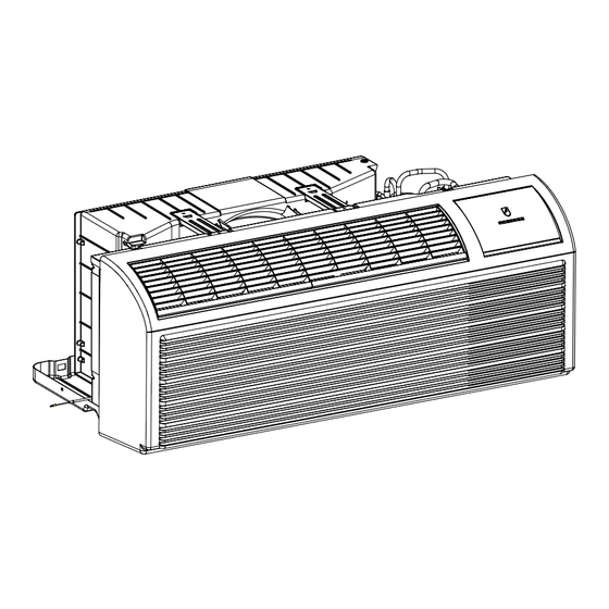
- Page 1 Zoneaire Select R-32 Series ® PTAC Packaged Terminal Air Conditioners & Heat Pumps Standard Chassis Models (R-32 Refrigerant) Electric Heat PZE07K3SC, PZE09K3SC, PZE12K3SC, PZE15K5SC PZE09R3SC, PZE12R3SC Heat Pump + Electric Heat PZH07K2SC, PZH07K3SC, PZH09K3SC, PZH12K3SC, PZH12K5SC, PZH15K3SC, PZH15K5SC PZH09R3SC, PZH12R3SC THE EXPERTS IN ROOM AIR CONDITIONING 945152000_01...
-
Page 2: Table Of Contents
Refrigerant Removal, Recovery, and Evacuation Component Replacement/Brazing Refrigerant Charging Compressor Replacement Compressor Replacement -Special Procedure in Case of Compressor Burnout WIRING DIAGRAMS APPENDIX Interactive Parts Viewer Limited Warranty Resistance Table of Thermistors (5K) Resistance Table of Thermistors (50K)(Compressor Discharge Sensor Friedrich Authorized Parts Depots... -
Page 3: Introduction
Installation procedures are not given in this manual. They are given in the Installation/Operation manual which can be acquired on the Friedrich website. Click the Link or scan the QR code to be directed to the Professional page where you can locate our technical literature. -
Page 4: Safety Group
CAUTION: Do Not Operate Equipment During Active Stages Of Construction To ensure proper operation, Friedrich requires that all equipment is not operated during active construction phases. This includes active stages of completing framing, drywalling, spackling, sanding, painting, flooring, and moulding in the equipment’s designated conditioning space. The use of this equipment during construction could result in premature failure of the components and/or system and is in violation of our standard warranty guidelines. -
Page 5: Safety First
INTRODUCTION Personal Injury Or Death Hazards WARNING AVERTISSEMENT ADVERTENCIA SAFETY Do not remove, disable or Ne pas supprime, désactiver ou No eliminar, desactivar o pasar por bypass this unit’s safety contourner cette l´unité des dispositifs alto los dispositivos de seguridad de FIRST devices. - Page 6 INTRODUCTION Personal Injury Or Death Hazards • REFRIGERATION SYSTEM REPAIR HAZARDS: • Use approved standard refrigerant recovering procedures and equipment to relieve high pressure before opening system for repair. • Do not allow liquid refrigerant to contact skin. Direct contact with liquid refrigerant can result in minor to moderate injury. •...
-
Page 7: Model Number Reference Guide
INTRODUCTION Model Number Reference Guide MODEL NUMBER V H 09 Engineering Digit Series PV = Friedrich Digital PTAC Design Series System H = Heat Pump with Auxiliary Heat Chassis F = FreshAire Nominal Capacity 09 = 9,000 Btuh 12 = 12,000 Btuh... -
Page 8: Operation Of Equipment In During Construction
INTRODUCTION Operation of Equipment in During Construction • OPERATION OF EQUIPMENT MUST BE AVOIDED DURING CONSTRUCTION PHASES WHICH WILL PRODUCE AIRBORNE DUST OR CONTAMINATES NEAR OR AROUND AIR INTAKE OPENINGS: • Wood or metal framing; • Drywalling or sheathing, • Spackling or applying joint compound. -
Page 9: Product Features
Product Features The new Friedrich digital PTAC has state of the art features to improve guest comfort,indoor air quality and conserve energy.Through the use of specifically designed control software for the PTAC industry Friedrich has accomplished what other.Manufacturer’s have only attempted –a quiet,dependable,affordable and easy to use PTAC. - Page 10 AIR FILTERS washable, reusable and easily accessed from the top of the unit without the removal of the front cover. Friedrich PTAC units are capable of introducing up to 30 CFM of outside air into the conditioned space. FILTERED FRESH AIR INTAKE The outdoor air passes through a washable mesh screen to prevent debris from entering the airstream.
-
Page 11: Specifications
SPECIFICATIONS Figure 201 Cool w/ Electric Heat (208/230V) Model PZE07K3SC PZE09K3SC PZE12K3SC PZE15K5SC Power supply V-Ph-Hz 230/208V /60Hz 230/208V/60Hz 230/208V /60Hz 230/208V/60Hz Single-phase power Single-phase power Single-phase power Single-phase power Power supply type supply supply supply supply Capacity Btu/h 7000/6800 9300/9100 12000/11800 14500/14300... - Page 12 SPECIFICATIONS Figure 201 Cool w/ Electric Heat (208/230V) Model PZE07K3SC PZE09K3SC PZE12K3SC PZE15K5SC Indoor Fan Noise Level(208V) cooling mode 52/50 52/50 54/51 53/50 Indoor sound level (sound pressure level) (Fan mode) dB(A)±2 49/44 49/40 52/45 52/45 Model YDK-55-4P2-4 YDK-55-4P2-4 YDK-AI-55-4P2 YDK-55-4P2-4 Brand chigo/KB...
-
Page 13: Cool W/ Electric Heat (265V)
SPECIFICATIONS Figure 202 Cool w/ Electric Heat (265V) Model PZE09R3SC PZE12R3SC Power supply V-Ph-Hz 265V/60Hz 265V/60Hz Power supply type Single-phase power(1Ph( Single-phase power(1Ph( Capacity Btu/h 9000 12300 Input 1150 Cooling Btu/h.W 11.5 10.7 Amps Capacity (230/208V) Btu/h 12000 12000 Electric heating Power input (230/208V) 3650 3650... - Page 14 SPECIFICATIONS Figure 202 Cool w/ Electric Heat (265V) Model PZE09R3SC PZE12R3SC Model YDK-45-4P2 YDK-45-4P2 Brand Insulation class Safe class IPX4 IPX4 Outdoor fan Input motor Output Rated current Capacitor Speed r/min 1600 1680 material ABS+G15 ABS+G15 Type axial flow axial flow Outdoor fan Diameter 13 3/4...
-
Page 15: Cool W/ Heat Pump + Electric Heat (208/230V) (7K And 9K Btu)
SPECIFICATIONS Figure 203 Cool w/ Heat Pump + Electric Heat (208/230V) (7k and 9k BTU) Model PZH07K2SC PZH07K3SC PZH09K3SC Power supply V-Ph-Hz 230/208V /60Hz 230/208V /60Hz 230/208V/60Hz Power supply type Single-phase power supply Single-phase power supply Single-phase power supply Capacity Btu/h 7000/6800 7000/6800... - Page 16 SPECIFICATIONS Figure 203 Cool w/ Heat Pump + Electric Heat (208/230V) (7k and 9k BTU) Model PZH07K2SC PZH07K3SC PZH09K3SC Indoor Fan Noise Level(230V)heating mode 53/51 53/51 52/50 Indoor Fan Noise Level(208V)heating mode 52/51 52/51 51/50 Indoor sound level (sound pressure level) (Fan mode) dB(A)±2 49/44...
-
Page 17: Cool W/ Heat Pump + Electric Heat (208/230V) (12K And 15K Btu)
SPECIFICATIONS Figure 204 Cool w/ Heat Pump + Electric Heat (208/230V) (12k and 15k BTU) Friedrich Model PZH12K3SC PZH12K5SC PZH15K5SC PZH15K3SC Power supply V-Ph-Hz 230/208V /60Hz 230/208V /60Hz 230/208V /60Hz 230/208V /60Hz Single-phase power Single-phase power Single-phase power Single-phase power... - Page 18 SPECIFICATIONS Figure 204 Cool w/ Heat Pump + Electric Heat (208/230V) (12k and 15k BTU) Friedrich Model PZH12K3SC PZH12K5SC PZH15K5SC PZH15K3SC Indoor Fan Noise Level((230V))cooling mode 54/52 54/52 54/50 54/50 Indoor Fan Noise Level(208V)cooling mode 54/51 54/51 53/50 53/50 Indoor Fan Noise Level(230V)heating...
- Page 19 SPECIFICATIONS Figure 205 Cool w/ Heat Pump + Electric Heat (265) Model PZH09R3SC PZH12R3SC Power supply V-Ph-Hz 265V/60Hz 265V/60Hz Power supply type Single-phase power(1Ph( Single-phase power(1Ph( Capacity Btu/h 9000 12300 Input 1150 Cooling Btu/h.W 11.5 10.7 Amps Capacity Btu/h 8200 10800 Input 1005...
-
Page 20: Cool W/ Heat Pump + Electric Heat (265)
SPECIFICATIONS Figure 205 Cool w/ Heat Pump + Electric Heat (265) Indoor Fan Noise Level(208V)cooling mode Indoor Fan Noise Level(230V)heating mode 51/50(265v) 54/51(265v) Indoor Fan Noise Level(208V)heating mode Indoor sound level (sound pressure level) (Fan mode) dB(A)±2 49/45 52/46 Model YDK-45-4P2 YDK-45-4P2 Brand... - Page 21 SPECIFICATIONS 21 1/2 Unit:inch Figure 205 ( Chassis Specs) Figure 206 (Typical Unit Components and Dimensions)
-
Page 22: Electrical Data
Failure to do so can result in property damage, personal injury and/or death. B. Power Cord Information (230/208V models only) All Friedrich 230/208V PTAC units are shipped from the factory with a Figure 14 Leakage Current Detection Interrupter (LCDI) equipped power cord. The... -
Page 23: Operation
OPERATION Function and Control Buttons and Display 1) Buttons There are ON/OFF, UP, DOWN, HEAT, COOL, CONSTANT FAN and fan speed of HIGH, LOW, AUTO buttons. 1. ON/OFF: Press to turn power on or off to the unit. 2. COOL, HEAT: choose the mode of operation 3. - Page 24 OPERATION Function and Control (After reprogramming, disconnect the power cord and then power up again to make it effective) Warning: #2 and #3 should be matched the unit type, but #2 can be switched to OFF to set as Emergency Heat Override! This will cause the E-heater to run all the time.
-
Page 25: System Configuration Fresh Air Vent Control
OPERATION System Configuration Fresh Air Vent Control System Configuration Figure 25 Air Vent Control Location Fresh Air Vent Control The vent control lever is located on the left side of the unit,behind the front panel. NOTE: The vent door shipping hardware must be removed before using the vent control lever.See page 23, Figure21,(Remove Shipping Screw from Vent Door if present). -
Page 26: Digital Control User Input Configuration
OPERATION Digital Control User Input Configuration Digital Control User Input Configuration The adjustable control dip switches are located at the front portion of the digital Smart Center. The inputs are only visible and accessible with the front cover removed from the PTAC. Dip Switch Setting 5. -
Page 27: Digital Control Operation
OPERATION Digital Control Operation Digital Control Operation Figure 29 Digital Control Panel FRP029 ℉ vs ℃ Display Heat/Cool Models(PZE) The unit is factory configured to display all temperatures in degrees Fahr- After pressing the “Heat” button, adjust the set point and the unit will cycle enheit (℉). -
Page 28: Thermostat Installation
ThermostatConnections Remote Thermostat R = 24V Power from Unit All Friedrich PZ model PTAC units are factory configured to be controlled Y = Call for Cooling by either the chassis mounted Smart Center or a 24V remote wall mount- W = Call for Heating ed thermostat. -
Page 29: Auxiliary Controls
OPERATION Auxiliary Controls Front Desk Control Terminal WARNING The Friedrich PZ model PTAC has built-in provisions for connection to an external switch to control power to the unit. The switch can be a central Electrical Shock Hazard desk control system. -
Page 30: General Knowledge Sequence Of Refrigeration
OPERATION General Knowledge Sequence Of Refrigeration A good understanding of the basic operation of the refrigeration system is essential for the service technician. Without this understanding, accurate troubleshooting of refrigeration system problems will be more difficult and time consuming, if not (in some cases) entirely impossible. The refrigeration system uses four basic principles in its operation which are as follows: “Heat always flows from a warmer body to a cooler body.”... -
Page 31: Refrigerant System Diagram
OPERATION Refrigerant System Diagram (1)Cooling + Heat Pump + Auxiliary Electric Heater CENTRIFUGAL AXIAL FAN OR CROSS FAN COOLED AIR HOT DISCHARGED AIR HOT AIR COOLED AIR COMPRESSOR INDOOR COILS OUTDOOR COILS ELECTRIC HEATER CAPILLARY NOTES: COOLING MODE REFRIGERANT FLOW DIRECTION HEATING MODE (2) Cooling + Electric Heater Figure 301 (Sequence of Operation) -
Page 32: Troubleshooting
TROUBLESHOOTING Table 501 Error code and solutions ERROR Meaning Problem Solutions CODE Room Temp. Sensor T1 - room temp sensor open or shorted circuit Refer to Thermistor checks Failure Evaporator Coil Temp T2 - evaporator coil temp sensor open or shorted circuit Refer to Thermistor checks Sensor Failure Air blow out over heat... -
Page 33: Unit Lost Power
TROUBLESHOOTING Unit Lost Power 1. Make sure the wiring is adequate for your unit. Warning: DO NOT use an extension cord. 2. Make sure that the receptacle is compatible with the air conditioner cord plug provided. 3. Test the power cord. Refer to the Electrical Data page to find power requirements, receptacle size, and test for power cord. -
Page 34: Control Panel Does Not Work
TROUBLESHOOTING Control Panel Does Not Work If the power supply is normal, but the control panel does not work, maybe the 24 V thermostat is in control. Check the thermostat; In standby mode, simultaneously press the [HEAT] key and the [+] key on the operation panel for 5 seconds or the [COOL] and [+] keys for 5 seconds to switch between them;... -
Page 35: Malfunction Of Temperature Sensor
TROUBLESHOOTING Malfunction of Temperature Sensor E2/E3/E4/E5 1. Remove Power from Unit. Remove front Panel. Open electrical Control Box. 4. Using a multi meter ohm across applicable pins for the sensor you are checking. 5. Refer to thermistor charts in Appendix for resistance and temperature deviation. E2 Error 5k Room Temp. -
Page 36: E4 Function Error
TROUBLESHOOTING Troubleshooting E4 Function Error Error code: Indoor Outlet Air Overheat Protection in Electric heating mode Indoor Outlet Air Overheat Protection Check if the indoor inlet、outlet、 Remove dirt and keep it filter and evaporator are blocked unobstructed Check the connection between the Check if the indoor fan motor Check if the fan capacitor is indoor motor and power board... -
Page 37: E8 Function Error
TROUBLESHOOTING Troubleshooting E8 Function Error Error code: Cooling/Heat Pump Overload, Outdoor/Indoor Coil Overheat Cooling/Heat Pump Overload, Outdoor/Indoor Coil Overheat Make sure the indoor and outdoor grilles are not blocked; Make sure the indoor fan and outdoor fan are both working well; ... -
Page 38: E9 Function Error
TROUBLESHOOTING E9 Function Error Error code: E9: T3 high temperature protection Reasons and solutions: 1. Outdoor air circulation is bad. Check if any obstacle blocks the air circulation. 2. Condenser is too dirty. Wash the condenser. Figure 507 3. Unit installation error. If the wall sleeve is too wide, the condenser can not exchange air well with the ambient air. Correct the installation. Refer to the Installation/ Operation manual. -
Page 39: Electric Heater Not Running
TROUBLESHOOTING Electric Heater Not Running 1. Indoor unit air circulation is blocked. Remove the obstacle. 2. DIP switch of NO.3 is in OFF position. Set it to ON position. 3. Remove power from the unit. Remove front panel (refer to to figure 701). Heater relay Open electrical control box (refer to figures 702 thru 705). -
Page 40: Component Testing
COMPONENT TESTING Check Indoor Fan Motor WARNING RISK OF ELECTRIC SHOCK Unplug and/or disconnect all electrical power to the unit before performing inspections, Indoor Motor maintenances or service. Control Failure to do so could result in electric shock, Connector serious injury or death. 1. -
Page 41: Check Outdoor Fan Motor
COMPONENT TESTING Check Outdoor Fan Motor WARNING RISK OF ELECTRIC SHOCK Unplug and/or disconnect all electrical power to the unit before performing inspections, maintenances or service. Failure to do so could result in electric shock, serious injury or death. Remove power from unit. cond/pump terminal 2. -
Page 42: Check Fan Motor Capacitors
COMPONENT TESTING Check Fan Motor Capacitors 1. Remove power from the unit. Open electrical Control Box. WARNING RISK OF ELECTRIC SHOCK Unplug and/or disconnect all electrical power to the unit before performing inspections, maintenances or service. Failure to do so could result in electric shock, serious injury or death. -
Page 43: Main Pcb Board Connector Identification
COMPONENT TESTING Main PCB Board Connector Identification Main PCB introduction Four-way valve control Power Input Neutral Wire Heater size jumper –factory set Voltage Transformer Input Compressor Control Outdoor Motor Control Relay Indoor Motor Control DEBUG interface Electric Heater Relay Indoor (VAC) FAN interface T1 Indoor temp sensor T2 Evaporator coil temp sensor Electric Heater... -
Page 44: Reversing Valve
COMPONENT TESTING Reversing Valve A reversing valve is a component of a heat pump that changes the direction of WARNING refrigerant flow, allowing the system to function in both heating and cooling modes. ELECTRIC SHOCK HAZARD It consists of a pressure-operated, main valve and a pilot valve actuated by a Disconnect power to the unit before solenoid plunger. -
Page 45: Compressor Checks
COMPONENT TESTING Compressor Checks WARNING WARNING ELECTRIC SHOCK HAZARD BURN HAZARD Turn off electric power before service or installation. Proper safety procedures must be followed, All electrical connections and wiring MUST be and proper protective clothing must be worn when working with a torch. the National Electrical Code and all local codes which have jurisdiction. - Page 46 COMPONENT TESTING Compressor Checks WARNING WARNING HIGH PRESSURE HAZARD ELECTRIC SHOCK HAZARD Sealed Refrigeration System contains refrigerant Turn off electric power before service or and oil under high pressure. installation. Extreme care must be used, if it Proper safety procedures must be followed, becomes necessary to work on equipment with and proper protective clothing must be worn power applied.
-
Page 47: Unit Disassembly And Component Replacement
UNIT DISASSEMBLY AND COMPONENT REPLACEMENT Remove Chassis WARNING ELECTRIC SHOCK HAZARD Turn off electric power before service or installation. Extreme care must be used, if it becomes necessary to work on equipment with power applied. Failure to do so could result in serious injury or death. -
Page 48: Remove Operation Panel
UNIT DISASSEMBLY AND COMPONENT REPLACEMENT Remove Operation panel WARNING ELECTRIC SHOCK HAZARD Turn off electric power before service or installation. Extreme care must be used, if it Remove Screw becomes necessary to work on equipment with power applied. Failure to do so could result in serious injury or death. -
Page 49: Open Electrical Control Box
UNIT DISASSEMBLY AND COMPONENT REPLACEMENT Open Electrical Control Box WARNING ELECTRIC SHOCK HAZARD Turn off electric power before service or installation. Extreme care must be used, if it becomes necessary to work on equipment with Remove 7 Screws power applied. Failure to do so could result in serious injury or death. -
Page 50: Remove Main Pcb (Logic) Board
UNIT DISASSEMBLY AND COMPONENT REPLACEMENT Remove Main PCB (logic) Board WARNING ELECTRIC SHOCK HAZARD Turn off electric power before service or installation. Extreme care must be used, if it becomes necessary to work on equipment with power applied. Stando (4 Places) Failure to do so could result in serious injury or death. -
Page 51: Remove Power Cord
UNIT DISASSEMBLY AND COMPONENT REPLACEMENT Remove Power Cord WARNING ELECTRIC SHOCK HAZARD Turn off electric power before service or installation. Extreme care must be used, if it becomes necessary to work on equipment with power applied. Failure to do so could result in serious injury or death. -
Page 52: Remove Blower Wheel Housing, Blower Wheel, Motor And Electric Heater
UNIT DISASSEMBLY AND COMPONENT REPLACEMENT Remove Blower Wheel Housing, Blower wheel, Motor and Electric Heater WARNING ELECTRIC SHOCK HAZARD Turn off electric power before service or installation. Extreme care must be used, if it becomes necessary to work on equipment with power applied. - Page 53 UNIT DISASSEMBLY AND COMPONENT REPLACEMENT Remove Blower Wheel Housing, Blower wheel, Motor and Electric Heater 3. Slide blower housing assembly out of unit (See figure 710). Blower housing left Panel Heater Brackets Figure 710 (Slide up Housing) 4. Replace Blower Wheel. a.
- Page 54 UNIT DISASSEMBLY AND COMPONENT REPLACEMENT Remove Blower Wheel Housing, Blower wheel, Motor and Electric Heater d. Remove fan mount bracket (3 screws) (See Figure 713) e. Remove motor. Blower Wheel Motor Bracket Figure 713( Motor Bracket) 6. Replace heater Open Electrical control box. b.
-
Page 55: Remove Outdoor Fan
UNIT DISASSEMBLY AND COMPONENT REPLACEMENT Remove Outdoor Fan WARNING ELECTRIC SHOCK HAZARD Turn off electric power before service or installation. Extreme care must be used, if it becomes necessary to work on equipment with power applied. Shroud Failure to do so could result in serious injury or Supports death. -
Page 56: R-32 Sealed System Repair
R-32 SEALED SYSTEM REPAIR General Information WARNING: Electrical Shock Hazard Disconnect all power to the unit before starting maintenance. All electrical connections and wiring MUST be installed by a qualified electrician and conform to all codes which have jurisdiction. Failure to do so can result in property damage, severe electrical shock or death. - Page 57 R-32 SEALED SYSTEM REPAIR General Information Warning: No ignition sources: No person carrying out work in relation to a REFRIGERATING SYSTEM which involves exposing any pipe work shall use any sources of ignition in such a manner that it may lead to the risk of fire or explosion. All possible ignition sources, including cigarette smoking, should be kept sufficiently far away from the site of installation, repairing, removing and disposal, during which refrigerant can possibly be released to the surrounding space.
-
Page 58: Required Equipment
R-32 SEALED SYSTEM REPAIR Required Equipment • Multi-meter • Ampmeter • R-32 E.P.A. Approved Refrigerant Recovery System • Vacuum Pump rated for R-32 refrigerant (capable of 300 microns or less vacuum.) • Oxy/ Acetylene torch or similar equipment utilized for brazing. •... -
Page 59: Refrigerant Removal, Recovery, And Evacuation
R-32 SEALED SYSTEM REPAIR Refrigerant Removal, Recovery, and Evacuation NOTE: When accessing the refrigerant in the system to make repairs or for any other purpose, conventional procedures shall be used. However, for FLAMMABLE REFRIGERANTS (R-32 is classified in the A2L group for mildly flammable refigerants) it is important that best practice is followed since flammability is a consideration. -
Page 60: Component Replacement/Brazing
R-32 SEALED SYSTEM REPAIR Component Replacement/Brazing Warning: • Ensure sufficient ventilation at the repair place. Warning: Presence of fire extinguisher. If any hot work is to be conducted on the refrigerating equipment or any associated parts, have a ABC class fire extinguisher available to hand. Warning: No person carrying out work in relation to a REFRIGERATING SYSTEM which involves exposing any pipe work shall use any sources of ignition in such a manner that it may lead to the risk of fire or explosion. -
Page 61: Refrigerant Charging
R-32 SEALED SYSTEM REPAIRS Refrigerant Charging WARNING: Electrical Shock Hazard Disconnect all power to the unit before starting maintenance. All electrical connections and wiring MUST be installed by a qualified electrician and conform to all codes which have jurisdiction. Failure to do so can result in property damage, severe electrical shock or death. WARNING: This Product uses R-32 Refrigerant Do not use means to accelerate the defrosting process or to clean, other than those recommended by the manufacturer. -
Page 62: Burn Hazard
R-32 SEALED SYSTEM REPAIRS Refrigerant Charging CAUTION WARNING FREEZE HAZARD BURN HAZARD Proper safety procedures must be followed, Proper safety procedures must be followed, and proper protective clothing must be worn and proper protective clothing must be worn when working with liquid refrigerant. when working with a torch. -
Page 63: Compressor Replacement
R-32 SEALED SYSTEM REPAIRS Compressor Replacement 1. Be certain to perform all necessary electrical and refrigeration tests to be sure the compressor is actually defective before replacing. WARNING 2. Recover all refrigerant from the system though the process tubes. ELECTRIC SHOCK HAZARD Turn off electric power before service or Refer to Refrigerant Removal, Recovery, and Evacuation Section... -
Page 64: Compressor Replacement -Special Procedure In Case Of Compressor Burnout
R-32 SEALED SYSTEM REPAIRS Compressor Replacement -Special Procedure in Case of Compressor Burnout 1. Recover all refrigerant and oil from the system. Refer to Refrigerant Removal, Recovery, and Evacuation Section of this manual. WARNING 2. Remove compressor, capillary tube and filter drier from the system. HIGH PRESSURE HAZARD Sealed Refrigeration System contains refrigerant CAUTION: Seal all openings on the defective compressor immediately. -
Page 65: Wiring Diagrams
WIRING DIAGRAMS 802022000115 CIRCUIT DIAGRAM GN(YE/GN) COMP YE/GN COMPRESSOR THERMO THERMO HEATER FUSE1 FUSE2 L2(N) L2(N) COMP ELEC_L/GAS ELEC_N YE/GN TRANS_IN COND/PUMP CONDENSER MOTOR HEATER-3KW TRANS_24V HEATER-2KW H_COM TRANS_11V TRANSFORMER CONTROL PANEL IR RECEIVER YE/GN 2 3 4 5 6 AC-FAN EVAPORATOR MOTOR T1 T2... -
Page 66: Pzh
WIRING DIAGRAMS 802022000114 CIRCUIT DIAGRAM GN(YE/GN) COMP YE/GN COMPRESSOR THERMO THERMO HEATER FUSE1 FUSE2 L2(N) L2(N) COMP ELEC_L/GAS ELEC_N YE/GN 4 WAY VALVE COIL TRANS_IN COND/PUMP CONDENSER MOTOR HEATER-3KW TRANS_24V HEATER-2KW H_COM TRANS_11V TRANSFORMER CONTROL PANEL IR RECEIVER YE/GN 2 3 4 5 6 AC-FAN EVAPORATOR MOTOR T1 T2 T3... -
Page 67: Appendix
APPENDIX Interactive Parts Viewer All Friedrich Service Parts can be found on our online interactive parts viewer. Please click on the link below: Interactive Parts Viewer For Further Assistance contact Friedrich customer service at (1-800-541-6645). Limited Warranty Current warranty information can be obtained by referring to... -
Page 68: Appendix 1: Reference Sheet Of Celsius And Fahrenheit
APPENDIX Service Manual Reference Sheet of Celsius and Fahrenheit Appendix: Appendix 1: Reference Sheet of Celsius and Fahrenheit Conversion formula for Fahrenheit degree and Celsius degree: Tf=Tcx1.8+32 Set temperature Fahrenheit Fahrenheit Fahrenheit display Fahrenheit display Fahrenheit Celsius display Fahrenheit Celsius Celsius(°C) temperature (°F) -
Page 69: Resistance Table Of Thermistors (5K)
APPENDIX Resistance Table of Thermistors (5K) Temp Resis Temp Resis Temp Resis Temp Resis Temp Resis 130100 34252 10785 8275 3119 125518 33209 10499 8063 3048 121114 32202 10221 7857 2980 116881 31228 9952 7657 2913 112811 30288 9690 7462 2848 108898 29378... - Page 70 APPENDIX Resistance Table of Thermistors (5K) Temp Resis Temp Resis Temp Resis Temp Resis Temp Resis 1321 1294 1269 1244 1219 1195 1171 1148 1126 1104 1083 1062 1041 1021 1001...
-
Page 71: Resistance Table Of Thermistors (50K)(Compressor Discharge Sensor
APPENDIX Resistance Table of Thermistors (50K)(Compressor Discharge Sensor Temp Resis Temp Resis Temp Resis Temp Resis Temp Resis 167862 42664 13052 4649 1878 161791 41332 12698 4538 1839 155965 40047 12354 4431 1800 150368 38805 12021 4326 1763 144994 37607 11698 4224 1726... - Page 72 APPENDIX Resistance Table of Thermistors (50K) (Compressor Discharge Sensor Temp Resis Temp Resis Temp Resis Temp Resis Temp Resis...
-
Page 73: Friedrich Authorized Parts Depots
APPENDIX Friedrich Authorized Parts Depots United Products Distributors Inc. The Gabbert Company Total Home Supply 4030A Benson Ave 6868 Ardmore 26 Chapin Rd Ste 1109 Halethorpe, MD 21227 Houston, Texas 77054 Pine Brook, NJ 07058 888-907-9675 877-847-0050 c.businsky@updinc.com 713-747-4110 support@totalhomesupply.com 800-458-4110 https://www.totalhomesupply.com/...
Need help?
Do you have a question about the Zoneaire Select R-32 Series and is the answer not in the manual?
Questions and answers