
Related Manuals for Gigabyte G383-R80-AAP1


Summary of Contents for Gigabyte G383-R80-AAP1
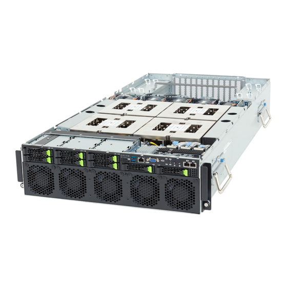
- Page 1 G383-R80-AAP1 HPC/AI Server - AMD Instinct™ MI300A APU 3U 8-Bay Gen5 NVMe User Manual Rev. 1.0...
- Page 2 For GIGABYTE distributors and resellers, additional sales & marketing materials are available from our reseller portal: http://reseller.b2b.gigabyte.com For further technical assistance, please contact your GIGABYTE representative or visit https://esupport.gigabyte.com/ to create a new support ticket For any general sales or marketing enquiries, you may also message GIGABYTE server directly by email: server.grp@gigabyte.com...
- Page 3 Conventions The following conventions are used in this user's guide: NOTE! Pieces of additional information related to the current topic. CAUTION! Precautionary measures to avoid possible hardware or software problems. WARNING! Alerts to any damage that might result from doing or not doing specific actions.
-
Page 4: Server Warnings And Cautions
Server Warnings and Cautions Before installing a server, be sure that you understand the following warnings and cautions. WARNING! To reduce the risk of electric shock or damage to the equipment: • Do not disable the power cord grounding plug. The grounding plug is an important safety feature. -
Page 5: Electrostatic Discharge (Esd)
Electrostatic Discharge (ESD) CAUTION! ESD CAN DAMAGE DRIVES, BOARDS, AND OTHER PARTS. WE RECOMMEND THAT YOU PERFORM ALL PROCEDURES AT AN ESD WORKSTATION. IF ONE IS NOT AVAILABLE, PROVIDE SOME ESD PROTECTION BY WEARING AN ANTI-STATIC WRIST STRAP AT- TACHED TO CHASSIS GROUND -- ANY UNPAINTED METAL SURFACE -- ON YOUR SERVER WHEN HANDLING PARTS. - Page 6 Installing or removing jumpers: A jumper is a small plastic encased conductor that slips over two jumper pins. Some jumpers have a small tab on top that can be gripped with fin-gertips or with a pair of fine needle nosed pliers. If the jumpers do not have such a tab, take care when us- ing needle nosed pliers to remove or install a jumper;...
-
Page 7: Table Of Contents
Table of Contents Chapter 1 Hardware Installation ..................9 Installation Precautions ..................9 Product Specifications ..................10 System Block Diagram ................... 12 Chapter 2 System Appearance ..................14 Front View ...................... 14 Rear View ....................... 15 Top View ......................16 Front Panel LEDs and Buttons ............... 17 Front System LAN LEDs ................ - Page 8 5-2-7 USB Configuration ....................51 5-2-8 Network Stack Configuration ..................53 5-2-9 NVMe Configuration ....................54 5-2-10 Graphic Output Configuration .................55 5-2-11 Tls Auth Configuration ....................56 5-2-12 RAM Disk Configuration ..................57 5-2-13 Broadcom(R) BCM57416 NetXtreme-E 10GBASE-T Network Connection ...58 5-2-14 VLAN Configuration ....................60 5-2-15 MAC IPv4 Network Configuration ................61 5-2-16 MAC IPv6 Network Configuration ................62 AMD CBS Menu .....................
-
Page 9: Chapter 1 Hardware Installation
Chapter 1 Hardware Installation Installation Precautions The motherboard/system contain numerous delicate electronic circuits and components which can become damaged as a result of electrostatic discharge (ESD). Prior to installation, carefully read the service guide and follow these procedures: • Prior to installation, do not remove or break motherboard S/N (Serial Number) sticker or warranty sticker provided by your dealer. -
Page 10: Product Specifications
Product Specifications NOTE: We reserve the right to make any changes to the product specifications and product-related information without prior notice. System Security Server Socket Operating Properties Š 3U Socket Security Server Operating Properties Dimension Š 447 (W) x 131 (H) x 950 (D) mm System fan Power Supply Superchip... - Page 11 Š 3+1 3000W 80 PLUS Titanium redundant power supplies System Š Aspeed® AST2600 management controller Management Š GIGABYTE Management Console (AMI MegaRAC SP-X) web interface Š Dashboard Š HTML5 KVM Š Sensor Monitor (Voltage, RPM, Temperature, CPU Status …etc.) Š Sensor Reading History Data Š...
-
Page 12: System Block Diagram
System Block Diagram Front Panel NVMe x2 PCIe5.0 x4 PCIe switch NVMe x2 NVMe x2 Broadcom PCIe3.0 x8 NVMe x2 Broadcom PEX89024 BCM57416 NCSI 8-bay 2.5” Gen5 NVMe 10GbE LAN 4 x PCIe5.0 x16 FHFL slots ASPEED PCIe5.0 x16 AST2600 10/100/1G MLAN PCIe5.0 x16... -
Page 13: Chapter 2 System Appearance
Chapter 2 System Appearance Front View 1 2 3 HDD0 HDD2 HDD4 HDD1 HDD3 HDD5 HDD6 HDD7 Description 2 x USB 3.2 Gen1 Management LAN Port VGA Port Front Panel LEDs and Buttons 2 x Data LAN Port • Refer to section 2-3 Front Panel LEDs and Buttons for a detailed description of the function of the LEDs. -
Page 14: Rear View
Rear View PSU4 PSU2 PSU3 PSU1 Description 4 x FHFL single PCIe Gen5 x16 Slots 4 x FHFL dual PCIe Gen5 x16 Slots System Appearance - 15 -... -
Page 15: Top View
Top View APU2 APU1 APU3 APU0 Description Description 2.5” Hard Drive Bay Power Supply Units (Top: PSU2/ Bottom: PSU1) MI300A APUs PCIe Card Slot System Fan Power Supply Units (Top: PSU4/ Bottom: PSU3) System Appearance - 16 -... -
Page 16: Front Panel Leds And Buttons
Front Panel LEDs and Buttons No. Name Color Status Description Blue System identification is active. ID Button with LED System identification is disabled. Green Indicates the system is powered on. Power button with LED System is not powered on or in ACPI S5 state (power off) Indicates locating the HDD. -
Page 17: Front System Lan Leds
Front System LAN LEDs Name Color Status Description Yellow 10 Gbps data rate 10GbE Green 1 Gbps data rate Speed LED 100 Mbps data rate Link between system and network or no access Green 10GbE Link / Blink Data transmission or reception is occurring. Activity LED No data transmission or reception is occurring. -
Page 18: Power Supply Unit Led
Power Supply Unit LED PSU LED State Description No AC power to all power supplies 1Hz Green Blinking AC present / only standby on / Cold redundant mode 2Hz Green Blinking Power supply firmware updating mode AC cord unplugged or AC power lost; with a second power supply in parallel still with AC input power Amber Power supply critical event causing shut down:... -
Page 19: Hard Disk Drive Leds
Hard Disk Drive LEDs LED #1 2.5” HDD LED #2 HDD Present RAID SKU LED #1 Locate Rebuilding HDD Access Fault (No Access) Green ON(*1) BLINK (*2) Disk LED (LED on Back Panel) Amber No RAID configuration Removed HDD Green ON(*1) (via HBA) Slot (LED on... -
Page 20: Chapter 3 System Hardware Installation
Chapter 3 System Hardware Installation Pre-installation Instructions Computer components and electronic circuit boards can be damaged by discharges of static electricity. Working on computers that are still connected to a power supply can be extremely dangerous. Follow the simple guidelines below to avoid damage to your computer or injury to yourself. -
Page 21: Removing And Installing The Chassis Cover
Removing and Installing the Chassis Cover Before you remove or install the system cover • Make sure the system is not turned on or connected to AC power. Follow these instructions to remove the chassis cover: Remove the screw securing the chassis cover. Unlock the plastic handle and pull the grip handle to open the panel cover. -
Page 22: Removing And Installing The Hard Disk Drive
Removing and Installing the Hard Disk Drive Read the following guidelines before you begin to install the hard disk drive: • Take note of the HDD tray orientation before sliding it out. • The tray will not fit back into the bay if it is inserted incorrectly. •... -
Page 23: Removing And Installing The Pcie Card
Removing and Installing the PCIe Card • Voltages can be present within the server whenever an AC power source is connected. This voltage is present even when the main power switch is in the off position. Ensure that the system is powered off and all power sources have been disconnected from the server prior to installing a PCIe card. -
Page 24: Installing The M.2 Device And Heat Sink
Installing the M.2 Device and Heat Sink CAUTION The position of the stand-off screw will depend on the size of the M.2 device. The stand-off screw is pre-installed for 22110 cards as standard. Refer to the size of the M.2 device and change the position of the stand-off screw accordingly. -
Page 25: Removing And Installing The Power Supply
Removing and Installing the Power Supply Follow these instructions to replace the power supply: Flip up and then grasp the power supply handle. Press the retaining clip on the right side of the power supply unit in the direction indicated. Pull out the power supply unit using the handle. -
Page 26: Cable Routing
Cable Routing APU2 APU1 APU3 APU0 Motherboard: MCIO_FIO_A Front IO Board M.2 and LEDs/Buttons Signal Cable Front IO Board: A Motherboard: MCIO_FIO_B Front Panel USB 3 Ports Cable Front IO Board: B Motherboard: MCIO_FIO_C PCIe Gen3 Signal Cable for BCM57416 Front IO Board: C Motherboard: PWR_FIO Front IO Board Power Cable... - Page 27 APU2 APU1 APU3 APU0 Motherboard: ATX1 HDD Backplane Board Power Cable Front HDD Board: ATX1 Motherboard: BP_1 HDD Backplane Board Signal Cable Front HDD Board: BP_1 System Hardware Installation - 28 -...
- Page 28 APU2 APU1 APU3 APU0 Motherboard: MCIO_P3 Motherboard: MCIO_P1 NVMe 0-1 NVMe 4-5 Front HDD Board: Front HDD Board: Cable Cable C1: U.2_4 A1: U.2_0 C2: U.2_5 A2: U.2_1 Motherboard: MCIO_P2 Motherboard: MCIO_P0 NVMe 2-3 NVMe 6-7 Front HDD Board: Front HDD Board: Cable Cable B1: U.2_2...
- Page 29 APU2 APU1 APU3 APU0 Motherboard: MCIO3 Motherboard: MCIO6 PCIe Riser Bracket: Slot 11 PCIe Riser Bracket: Slot 6 Motherboard: MCIO4 Motherboard: MCIO5 System System Rear PCIe Riser Bracket: Slot 8 PCIe Riser Bracket: Slot 2 Rear Side Side PCIe PCIe Cable Cable Motherboard: MCIO1 Motherboard: MCIO8...
-
Page 30: Chapter 4 System Components
Chapter 4 System Components Motherboard Components APU2 APU1 APU3 APU0 BIOS2 BIOS1 BMC2 BMC1 Item Description Item Description MCIO Connector (MCIO-P1/PCIe Gen5) MCIO Connector (MCIO-P3/PCIe Gen5) MCIO Connector (MCIO3/PCIe Gen5) BMC Firmware Readiness LED MCIO Connector (MCIO4/PCIe Gen5) MCIO Connector (MCIO-7/PCIe Gen5) MCIO Connector (MCIO1/PCIe Gen5) MCIO Connector (MCIO-8/PCIe Gen5) MCIO Connector (MCIO2/PCIe Gen5) -
Page 31: Jumper Settings
Jumper Settings Enable Clear CMOS CLR_CMOS Default APU2 APU1 APU3 APU0 Motherboard Components - 32 -... -
Page 32: Backplane Board Storage Connector
Backplane Board Storage Connector 4-3-1 CBPG680 (Front System Storage Board) Item Description MCIO Connector (MCIO 4i/U_2_0) MCIO Connector (MCIO 4i/U_2_1) MCIO Connector (MCIO 4i/U_2_2) MCIO Connector (MCIO 4i/U_2_3) MCIO Connector (MCIO 4i/U_2_4) MCIO Connector (MCIO 4i/U_2_5) MCIO Connector (MCIO 4i/U_2_6) MCIO Connector (MCIO 4i/U_2_7) MCIO Connector (MCIO 4i/SL_SAS0) MCIO Connector (MCIO 4i/SL_SAS1) -
Page 33: Chapter 5 Bios Setup
Chapter 5 BIOS Setup BIOS (Basic Input and Output System) records hardware parameters of the system in the EFI on the motherboard. Its major functions include conducting the Power-On Self-Test (POST) during system startup, saving system parameters, loading the operating system etc. The BIOS includes a BIOS Setup program that allows the user to modify basic system configuration settings or to activate certain system features. - Page 34 Main This setup page includes all the items of the standard compatible BIOS. Advanced This setup page includes all the items of AMI BIOS special enhanced features. (ex: Auto detect fan and temperature status, automatically configure hard disk parameters.) ...
-
Page 35: The Main Menu
The Main Menu Once you enter the BIOS Setup program, the Main Menu (as shown below) appears on the screen. Use arrow keys to move among the items and press <Enter> to accept or enter other sub-menu. Main Menu Help The on-screen description of a highlighted setup option is displayed on the bottom line of the Main Menu. - Page 36 Parameter Description BIOS Information Project Name Displays the project name information. Project Version Displays version number of the BIOS setup utility. Build Date and Time Displays the date and time when the BIOS setup utility was created. BMC Information (Note1) BMC Firmware Version (Note1) Displays BMC firmware version information.
- Page 37 Parameter Description Onboard LAN Information LAN1/LAN2 MAC Address (Note) Displays LAN MAC address information. System Date Sets the date following the weekday-month-day-year format. System Time Sets the system time following the hour-minute-second format. (Note) The number of LAN ports listed will depend on the motherboard / system model. BIOS Setup - 38 -...
-
Page 38: Advanced Menu
Advanced Menu The Advanced Menu displays submenu options for configuring the function of various hardware components. Select a submenu item, then press <Enter> to access the related submenu screen. When Boot Mode Select is set to UEFI (Default) BIOS Setup - 39 -... -
Page 39: Trusted Computing
5-2-1 Trusted Computing Parameter Description Configuration Enable/Disable BIOS support for security device. OS will not show security device. TCG EFI protocol and INT1A interface will not be Security Device Support available. Options available: Disabled, Enabled. Default setting is Enabled. Select Enable to activate TPM support feature. SPI TPM Support Options available: Disabled, Enabled. -
Page 40: Psp Firmware Versions
5-2-2 PSP Firmware Versions The PSP Firmware Versions page displays the basic PSP firmware version information. Items on this window are non-configurable. BIOS Setup - 41 -... -
Page 41: Ast2600 Super Io Configuration
5-2-3 AST2600 Super IO Configuration Description Parameter AST2600 Super IO Configuration Super IO Chip Displays the super IO chip information Serial Port 1 Press [Enter] for configuration of advanced items. Configuration BIOS Setup - 42 -... -
Page 42: Serial Port 1 Configuration
5-2-3-1 Serial Port 1 Configuration Description Parameter Serial Port 1 Configuration Enable/Disable the Serial Port (COM). When set to Enabled allows you to configure the Serial port 1 settings. When set to Disabled, displays no Serial Port (Note) configuration for the serial port. Options available: Disabled, Enabled. -
Page 43: Serial Port Console Redirection
5-2-4 Serial Port Console Redirection Parameter Description Select whether to enable console redirection for specified device. Console COM1/Serial Over LAN redirection enables the users to manage the system from a remote Console Redirection (Note) location. Options available: Enabled, Disabled. Default setting is Disabled. Press [Enter] to configure advanced items. - Page 44 Parameter Description Parity Š – A parity bit can be sent with the data bits to detect some transmission errors. – Even: parity bit is 0 if the num of 1's in the data bits is even. – Odd: parity bit is 0 if num of 1's in the data bits is odd. –...
- Page 45 Parameter Description Legacy Console Redirection Press [Enter] to configure advanced items. Redirection COM Port Š – Selects a COM port for Legacy serial redirection. – Default setting is COM1/SOL. Resolution Š – Selects the number of rows and columns used in Console Redirection for legacy OS support.
- Page 46 Parameter Description Flow Control Š – Flow control can prevent data loss from buffer overflow. When sending data, if the receiving buffers are full, a 'stop' signal can Serial Port for Out-of-Band be sent to stop the data flow. Once the buffers are empty, a 'start' EMS Console Redirection signal can be sent to re-start the flow.
-
Page 47: Cpu Configuration
5-2-5 CPU Configuration Description Parameter Enable/Disable the CPU Virtualization. SVM Mode Options available: Disabled, Enabled. Default setting is Enabled. Press [Enter] to view the memory information related to CPU 0/1. CPU 0/1/2/3 Information BIOS Setup - 48 -... -
Page 48: Pci Subsystem Settings
5-2-6 PCI Subsystem Settings BIOS Setup - 49 -... - Page 49 Description Parameter Displays the PCI Bus Driver version information. PCI Bus Driver Version Change PCIe lanes. SLOT# Options available: Disabled, Auto, x16, x8x8, x8x4x4, x4x4x8, Lanes (Note1) x4x4x4x4. Default setting is Auto. When enabled, this setting will initialize the device expansion ROM SLOT# for the related devices.
-
Page 50: Usb Configuration
5-2-7 USB Configuration Parameter Description USB Configuration USB Module Version Displays the USB module version information. USB Controllers Displays the supported USB controllers. USB Devices: Displays the USB devices connected to the system. Enable/Disable the Legacy USB support function. AUTO option disables legacy support if no USB devices are connected. - Page 51 Parameter Description Selects the time-out value during a USB mass storage device reset. Device reset time-out Options available: 10 sec, 20 sec, 30 sec, 40 sec. Default setting is 20 sec. Maximum time the device will take before it properly reports itself to the Host Controller.
-
Page 52: Network Stack Configuration
5-2-8 Network Stack Configuration Parameter Description Enable/Disable the UEFI network stack. Network Stack Options available: Enabled, Disabled. Default setting is Enabled. Enable/Disable the Ipv4 PXE feature. Ipv4 PXE Support (Note) Options available: Enabled, Disabled. Default setting is Enabled. Enable/Disable the Ipv4 HTTP feature. Ipv4 HTTP Support (Note) Options available: Enabled, Disabled. -
Page 53: Nvme Configuration
5-2-9 NVMe Configuration Parameter Description NVMe Configuration Displays the NVMe devices connected to the system. BIOS Setup - 54 -... -
Page 54: Graphic Output Configuration
5-2-10 Graphic Output Configuration Parameter Description Selects output device type. Output Device Type Options available: First loaded Device, Onboard Device, External Device, Specific Device. Default setting is Onboard Device. BIOS Setup - 55 -... -
Page 55: Tls Auth Configuration
5-2-11 Tls Auth Configuration Parameter Description Press [Enter] for configuration of advanced items. Enroll Cert Š – Press [Enter] to enroll a certificate • Enroll Cert Using File • Cert GUID Server CA Configuration Input digit character in 1111111-2222-3333-4444-1234567890ab format. –... -
Page 56: Ram Disk Configuration
5-2-12 RAM Disk Configuration Parameter Description Specifies the type of memory to use from available memory pool in system to create a disk. Disk Memory Type Options available: Boot Service Data, Reserved. Default setting is Boot Service Data. Creates a raw RAM disk. Size (Hex) Š... -
Page 57: Broadcom(R) Bcm57416 Netxtreme-E 10Gbase-T Network Connection
5-2-13 Broadcom(R) BCM57416 NetXtreme-E 10GBASE-T Network Connection Parameter Description Press [Enter] to view firmware image information. Firmware Image Menu Press [Enter] to configure advanced items. Multi-Function Mode Š – Configures the NIC Hardware Mode. – Options available: SF, NPAR 1.0. Default setting is SF. SR-IOV Š... - Page 58 Description Parameter Support RDMA Š – Enable/Disable RDMA support for this port. – Options available: Disabled, Enabled. Default setting is Disabled. DCB Protocol Š – Enable/Disable DCB protocol. – Options available: Disabled, Enabled (IEEE only), CEE (only), Both (IEEE preferred with fallback to CEE). Default setting is Disabled. LLDP nearest bridge Š...
-
Page 59: Vlan Configuration
5-2-14 VLAN Configuration Parameter Description Press [Enter] to configure advanced items. Create new VLAN Š VLAN ID Š – Sets VLAN ID for a new VLAN or an existing VLAN. – Press the <+> / <-> keys to increase or decrease the desired values. –... -
Page 60: Mac Ipv4 Network Configuration
5-2-15 MAC IPv4 Network Configuration Parameter Description Indicates whether network address is configured successfully or not. Configured Options available: Enabled, Disabled. Default setting is Disabled. Options available: Enabled, Disabled. Default setting is Disabled. Enable DHCP (Note) Local IP Address Press [Enter] to configure local IP address. (Note) Press [Enter] to configure local NetMask. -
Page 61: Mac Ipv6 Network Configuration
5-2-16 MAC IPv6 Network Configuration Parameter Description Press [Enter] to configure advanced items. Displays the MAC Address information. Š Interface ID Š – The 64 bit alternative interface ID for the device. The string is colon separated. e.g. ff:dd:88:66:cc:1:2:3. DAD Transmit Count Š... -
Page 62: Amd Cbs Menu
AMD CBS Menu AMD CBS menu displays submenu options for configuring the CPU-related information that the BIOS automatically sets. Select a submenu item, then press [Enter] to access the related submenu screen. BIOS Setup - 63 -... - Page 63 5-3-1 CPU Common Options BIOS Setup - 64 -...
-
Page 64: Cpu Common Options
Parameter Description CPU Common Options Performance Press [Enter] for configuration of advanced items. Allow REP-MOV/STOS to use non-caching streaming stores for large sizes. REP-MOV/STOS Streaming Options available: Disabled, Enabled. Default setting is Enabled. Prefetcher settings Press [Enter] for configuration of advanced items. Core Watchdog Press [Enter] for configuration of advanced items. - Page 65 Parameter Description Enable/Disable the PPIN feature. PPIN Opt-in Options available: Disabled, Enabled, Auto. Default setting is Auto. Enabled: Enter system memory is covered. SNP Memory (RMP Table) Options available: Disabled, Enabled, Custom, Auto. Coverage Default setting is Auto. Controls the Secure Memory Encryption Enable (SMEE) function. SMEE Options available: Disable, Enable, Auto.
- Page 66 5-3-1-1 Performance Parameter Description Performance Options available: Normal Operation, Customized. Default setting is Normal OC Mode (Note) Operation. Allows you to accept or decline enabling Custom Core Pstates. When Custom Core Pstates accepted, you can disable or customize core pstates. Allows you to accept or decline enabling CCDs, processor cores and threads.
- Page 67 5-3-1-2 Prefetcher Settings Parameter Description Prefetcher settings Enable/Disable L1 Stream HW Prefetcher. L1 Stream HW Prefetcher Options available: Disable, Enable, Auto. Default setting is Auto. Use memory access history of individual instructions to fetch additional lines when each access is a constant distance from the previous. L1 Stride Prefetcher Enable/Disable L1 Stride Prefetcher.
- Page 68 5-3-1-3 Core Watchdog Parameter Description Core Watchdog Enable/Disable CPU Watchdog Timer. Core Watchdog Timer Enable (Note) Options available: Disabled, Enabled, Auto. Default setting is Auto. Select the CPU Watchdog Timer interval. Options available: 2.681s, 1.340s, 669.41ms, 334.05ms, 166.37ms, Core Watchdog Timer Interval 82.53ms, 40.61ms, 20.970ms, 10.484ms,5.241ms, 2.620ms, 1.309ms, 654.08us, 326.4us, 162.56us, 80.64us, 39.68us, Auto.
-
Page 69: Df Common Options
5-3-2 DF Common Options Parameter Description DF Common Options Memory Addressing Press [Enter] for configuration of advanced items. ACPI Press [Enter] for configuration of advanced items. Link Press [Enter] for configuration of advanced items. Configures the Data Fabric watchdog timer interval. DF Watchdog Timer Interval Options available: Auto, 41ms, 166ms, 334ms, 669ms, 1.34 seconds, 2.68 seconds, 5.36 seconds. - Page 70 Modify the default number of segments for PCI. Custom PCI segments Option available: Enable, Disable. Default setting is Enable. BIOS Setup - 71 -...
-
Page 71: Memory Addressing
5-3-2-1 Memory Addressing Parameter Description Memory Addressing Specifies the number of desired NUMA nodes per socket. Options available: NPS0, NPS1, NPS2, NPS4, Auto. Default setting is Auto. NUMA nodes per socket NOTE! • Available options may vary by system configuration. •... - Page 72 5-3-2-2 ACPI Parameter Description ACPI ACPI SRAT L3 Cache As Enable/Disable report each L3 cache as a NUMA Domain to the OS. Options available: Disabled, Enabled, Auto. Default setting is Auto. NUMA Domain Determines how the SLIT distances are declared. ACPI SLIT Distance Control Options available: Manual, Auto.
- Page 73 5-3-2-3 Link Parameter Description Enable/Disable GMI link encryption. GMI encryption control Options available: Disabled, Enabled, Auto. Default setting is Auto. Enable/Disable xGMI link encryption. xGMI encryption control Options available: Disabled, Enabled, Auto. Default setting is Auto. Configures the number of xGMI2 links used on a multi-socket system. xGMI Link Configuration Options available: Auto, 3 xGMI Links, 4 xGMI Links, 2 xGMI Links + 2 PCI Links.
- Page 74 5-3-2-4 SDCI Parameter Description Press [Enter] for configuration of advanced items. CNLI Sublink Interleaving Š – Options available: Enable, Disable. Default setting is Enable. BIOS Setup - 75 -...
-
Page 75: Nbio Common Options
5-3-3 NBIO Common Options Parameter Description NBIO Common Options Enable/Disable the IOMMU function. IOMMU Options available: Enabled/Disabled. Default setting is Disabled. Enable DMAr system protection during POST. DMAr Support Options available: Auto,Enabled/Disabled. Default setting is Auto. DRTM Virtual Device Enable DRTM ACPI virtual device.. Support Options available: Auto,Enabled/Disabled. - Page 76 NBIO RAS Common Press [Enter] for configuration of advanced items. Options Enable/Disable Advanced Error Reporting Capability. Enable AER Cap Options available: Auto, Enabled, Disabled. Default setting is Auto. Configures Early Link Speed. Early Link Speed Options available: Auto, Gen1, Gen2. Default setting is Auto. Options available: OS First, Firmware First, System Firmware Intermediary, Hot Plug Handdling mode Firmware First but allow OS First, Auto.
- Page 77 5-3-3-1 SRIOV Parameter Description SRIOV SRIOV Enable Options available: Enabled/Disabled, Auto. Default setting is Auto. VF Doorbell Aperture size Press [Enter] to configure VF Doorbell Aperture size. Default setting is Auto. VF Mem Aperture size Press [Enter] to configure VF Mem Aperture size. Default setting is Auto. VF Reg Aperture size Press [Enter] to configure VF Reg Aperture size.
- Page 78 5-3-3-2 NBIO RAS Common Options Parameter Description NBIO RAS Common Options Options available: Disabled, MCA, Auto. Default setting is Auto. NBIO RAS Control Configures the Egress Poison High Severity. Each bit set to 1 enables Egress Poison Severity High High severity on the associated IOHC egress port. A bit of 0 indicates LOW severity.
- Page 79 Parameter Description Uncorrected Converted to Enables mask for masking of uncorrectable parity errors on internal Poison Enable Mask High arrays. Uncorrected Converted to Enables mask for masking of uncorrectable parity errors on internal Poison Enable Mask Low arrays. Specifies the timer interval of the SYSHUB Watchdog timer in System Hub Watchdog Timer milliseconds.
- Page 80 5-3-3-3 Link EQ Present Options Parameter Description Link EQ Present Options Press [Enter] for configuration of advanced items. GEN3 Present Search Mask Configuration Š – Options available: Auto, Custom, Enable. Default setting is Auto. Press [Enter] for configuration of advanced items. GEN4 Present Search Mask Configuration Š...
-
Page 81: Fch Common Options
5-3-4 FCH Common Options Parameter Description FCH Common Options I3C/I2C Configuration Options Press [Enter] for configuration of advanced items. USB Configuration Options Press [Enter] for configuration of advanced items. AC Power Loss Options Press [Enter] for configuration of advanced items. Uart Configuration Options Press [Enter] for configuration of advanced items. - Page 82 5-3-4-1 I3C/I2C Configuration Options Parameter Description I3C/I2C Configuration Options Options available: Both Disabled, I3C Enabled, I2C Enabled, Auto. I3C/I2C 0/1/2/3 Enable Default setting is Auto. I2C 4/5 Enable Options available: Disabled, Enabled, Auto. Default setting is Auto. Release SPD Host Control Options available: Disabled, Enabled, Auto.
- Page 83 5-3-4-2 USB Configuration Options Parameter Description USB Configuration Options Enable/Disable USB controller. XHCI Controller0/1 enable Options available: Enabled, Disabled, Auto. Default setting is Auto. USB ecc SMI Enable Options available: Enable, Off, Auto. Default setting is Auto. Press [Enter] for configuration of advanced items. MCM USB enable XHCI2/ XHCI3 enable (Socket1) Š...
- Page 84 5-3-4-3 AC Power Loss Options Parameter Description AC Power Loss Options Selects the AC Loss Control Method. AC Loss Control Options available: Power Off, Power On, Last State. Default setting is Last State. BIOS Setup - 85 -...
- Page 85 5-3-4-4 Uart Configuration Options Parameter Description Uart Configuration Options Uart 0/1/2 Enable Options available: Disabled, Enabled, Auto. Default setting is Auto. BIOS Setup - 86 -...
- Page 86 5-3-4-5 FCH RAS Options Parameter Description FCH RAS Options Enable/Disable the ALink RAS Support. ALink RAS Support Options available: Disabled, Enabled, Auto. Default setting is Auto. Enables AB to forward downstream sync-flood message to system Reset After Sync Flood controller. Options available: Enable, Disable, Auto.
-
Page 87: Miscellaneous Options
5-3-4-6 Miscellaneous Options Parameter Description Miscellaneous Options Enable/Disable Boot Timer. Boot Timer Enable Options available: Disabled, Enabled, Auto. Default setting is Auto. BIOS Setup - 88 -... - Page 88 5-3-5 SMU Common Options BIOS Setup - 89 -...
-
Page 89: Smu Common Options
Parameter Description SMU Common Options Enable/Disable the CPPC feature. CPPC Options available: Disabled, Enabled, Auto. Default setting is Auto. TDP Control Options available: Manual, Auto. Default setting is Auto. Configure TDP (W) PPT Control Options available: Manual, Auto. Default setting is Auto. Configure PPT (W) Selects use the fused Determinism or set customized Determinism. - Page 90 Parameter Description SVI3 Telemetry Control Options available: Auto, Manual. Default setting is Auto. SVI3 Telemetry Current Specfiiy the amount of SVI3 telemetry current margin. Guardband Options available: Auto, Manual. Default setting is Auto. Vddsoc TDC Control Vddsoc TDC Configure Vddsoc TDC Options available: Auto, Manual.
- Page 91 VddGfxVlotageMargin Configure VddGfx Vlotage Margin Options available: Positive, Negative. Default setting is Positive. VddCpuVlotageMarginSign VddCpuVlotageMargin Configure VddCpu Vlotage Margin Sign Options available: Positive, Negative. Default setting is Positive. VddSocVlotageMarginSign VddSocVlotageMargin Configure VddSoc Vlotage Margin Sign VddSocioVlotageMarginSign Options available: Positive, Negative. Default setting is Positive. VddSocioVlotageMargin Configure VddSocio Vlotage Margin Sign VddHbmVlotageMarginSign...
-
Page 92: Soc Miscellaneous
5-3-6 SOC Miscellaneous Parameter Description SOC Miscellaneous Control Enable/Disable the ConsoleOut function for ABL. ABL Console Out Control (Note) Options available: Disable, Enable, Auto. Default setting is Auto. ABL Console Out Serial Options available: eSPI, SOC UART0, SOC UART1, Auto. Default setting is Auto. -
Page 93: Hbm Common Options
5-3-7 HBM Common Options Parameter Description HBM Common Options Press [Enter] for advanced configuration. HBM DRAM Corrected Error Counter Leak Rate Š – Program Rate value for HBM DRAM Corrected Error Counter HBM RAS function. HBM DRAM Corrected Error Counter Leak Threshold. Š... -
Page 94: Gpu Common Options
5-3-8 GPU Common Options Parameter Description GPU Common Options Enable SRAM ECC on the accelerator's compute engines. GPU RAS Enable Options available: True, False. Default setting is True. BIOS Setup - 95 -... -
Page 95: Amd Pbs Menu
AMD PBS Menu AMD PBS Option menu displays submenu options for configuring the function of AMD PBS. Select a submenu item, then press [Enter] to access the related submenu screen. Parameter Description Press [Enter] for configuration of advanced items. Enable/Disable SPI Locking for protect ROM part. SPI Locking Options available: Disabled, Enabled. -
Page 96: Ras
5-4-1 RAS Parameter Description Enable/Disable the Periodic SMI for polling [MCA Threshold] error. RAS Periodic SMI Control Options available: Disabled, Enabled. Default setting is Enabled. SMI Threshold Configures the SMI Threshold value. SMI Scale Configures the SMI Scale value. Defines the unit of time scale. SMI Scale Unit Options available: millisecond, second, minute. - Page 97 Parameter Description PCIe Root Port UnCorr Err Initialize the PCIe AER Uncorrected Error Mask register of Root Port. Mask Reg PCIe Root Port UnCorr Err Initialize the PCIe AER Uncorrected Error Severity register of Root Port. Sev Reg PCIe Device Corr Err Mask Initialize the PCIe AER Corrected Error Mask register of PCIe device.
-
Page 98: Chipset Setup Menu
Chipset Setup Menu Chipset Setup menu displays submenu options for configuring the function of the North Bridge. Select a submenu item, then press <Enter> to access the related submenu screen. Parameter Description PCIe Link training in 1 or 2 steps. PCIe Link Training Type Options available: 1 Step, 2 Step. -
Page 99: Server Management Menu
Server Management Menu Parameter Description Enable/Disable FRB-2 timer (POST timer). FRB-2 Timer Default setting is Enabled. FRB-2 Timer Configures the FRB-2 Timer timeout. timeout Default setting is 20 minutes. Configures the FRB-2 Timer policy. FRB-2 Timer Policy Options available: Do Nothing, Reset, Power Down, Power Cycle. Default setting is Do Nothing. - Page 100 Parameter Description System Event Log Press [Enter] to configure advanced items. View FRU Press [Enter] to view the FRU information. Information BMC VLAN Press [Enter] to configure advanced items. Configuration BMC network Press [Enter] to configure advanced items. configuration IPv6 BMC Network Press [Enter] to configure advanced items.
-
Page 101: System Event Log
5-6-1 System Event Log Parameter Description Enabling / Disabling Options Change this item to enable or disable all features of System Event SEL Components Logging during boot. Options available: Disabled, Enabled. Default setting is Enabled. Erasing Settings Choose options for erasing SEL. Erase SEL Options available: No/Yes, On next reset/Yes, On every reset. -
Page 102: View Fru Information
5-6-2 View FRU Information The FRU page is a simple display page for basic system ID information, as well as System product information. Items on this window are non-configurable. (Note) The model name will vary depends on the product you purchased BIOS Setup - 103 -... -
Page 103: Bmc Vlan Configuration
5-6-3 BMC VLAN Configuration Description Parameter BMC VLAN Configuration Select to configure BMC VLAN ID. The valid range is from 0 to 4094. When BMC VLAN ID set to 0, BMC VLAN ID will be disabled. Select to configure BMC VLAN Priority. The valid range is from 0 to 7. BMC VLAN Priority When BMC VLAN ID is set to 0, BMC VLAN Priority will not be selected. -
Page 104: Bmc Network Configuration
5-6-4 BMC Network Configuration Parameter Description BMC network configuration Lan Channel 1 Selects to configure LAN channel parameters statically or dynamically (DHCP). Do nothing option will not modify any BMC network parameters Configuration Address source during BIOS phase. Options available: Unspecified, Static, DynamicBmcDhcp. Default setting is DynamicBmcDhcp. -
Page 105: Ipv6 Bmc Network Configuration
5-6-5 IPv6 BMC Network Configuration Parameter Description IPv6 BMC network configuration IPv6 BMC Lan Channel 1 Enable/Disable IPv6 BMC LAN channel function. When this item is disabled, the system will not modify any BMC network during BIOS IPv6 BMC Lan Option phase. -
Page 106: Security Menu
Security Menu The Security menu allows you to safeguard and protect the system from unauthorized use by setting up access passwords. There are two types of passwords that you can set: • Administrator Password Entering this password will allow the user to access and change all settings in the Setup Utility. •... -
Page 107: Secure Boot
5-7-1 Secure Boot The Secure Boot feature is applicable if supported by your Operating System. If your Operating System is not supporting Secure Boot, the system will hang when starting the Operating System. Parameter Description System Mode Displays if the system is in User mode or Setup mode. Enable/ Disable the Secure Boot function. - Page 108 Parameter Description Press [Enter] to configure advanced items. Please note that this item is configurable when Secure Boot Mode is set to Custom. Factory Key Provision Š – Allows to provision factory default Secure Boot keys when system is in Setup Mode.
-
Page 109: Boot Menu
Boot Menu The Boot menu allows you to set the drive priority during system boot-up. BIOS setup will display an error message if the legacy drive(s) specified is not bootable. Parameter Description Boot Configuration Number of seconds to wait for setup activation key. 65535 (0xFFFF) Setup Prompt Timeout means indefinite waiting. - Page 110 Parameter Description FIXED BOOT ORDER Priorities Press [Enter] to configure the boot priority. By default, the server searches for boot devices in the following sequence: Hard drive. Boot Option #1 / #2 / #3 / #4 / #5 CD-COM/DVD drive. USB device.
-
Page 111: Save & Exit Menu
Save & Exit Menu The Save & Exit menu displays the various options to quit from the BIOS setup. Highlight any of the exit options then press <Enter>. Parameter Description Save Options Saves changes made and closes the BIOS setup. Save Changes and Exit Options available: Yes, No. -
Page 112: Bios Recovery
5-10 BIOS Recovery The system has an embedded recovery technique. In the event that the BIOS becomes corrupt the boot block can be used to restore the BIOS to a working state. To restore your BIOS, please follow the instructions listed below: Recovery Instruction: 1. -
Page 113: Bios Post Beep Code (Ami Standard)
5-11 BIOS POST Beep code (AMI standard) 5-11-1 PEI Beep Codes # of Beeps Description Memory not Installed. Memory was installed twice (InstallPeiMemory routine in PEI Core called twice) Recovery started DXEIPL was not found DXE Core Firmware Volume was not found Recovery failed S3 Resume failed Reset PPI is not available...
Need help?
Do you have a question about the G383-R80-AAP1 and is the answer not in the manual?
Questions and answers