
Related Manuals for Applikon my-Control

Summary of Contents for Applikon my-Control
- Page 1 Autoclavable Bioreactors 2 and 3L HARDWARE MANUAL Hardware Version 3 Document Version 3.2...
-
Page 2: Table Of Contents
Related Manuals ..........................10 The my-Control ............................11 Front view of the my-Control ......................11 Rear View of the my-Control ......................12 Modules to be Mounted inside the my-Control ................13 Colors of the Front Panel .........................14 Front Panel Illumination ........................14 Actuator control ..........................15 3.6.1 Digital actuators versus Continuous Actuators ..............15... - Page 3 HARDWARE MANUAL CONTENTS my-Control for Autoclavable Bioreactors 2 and 3L Hardware Version 3, Document Version 3.2 Aeration ............................37 6.3.1 Gas In-/Outlet Filter ......................37 6.3.2 Spargers ..........................37 6.3.3 Air Overlay Assembly .......................38 6.3.4 Pressure Relief Valve ......................38 6.3.5 Air Outlet Condenser ......................39 6.3.6...
-
Page 4: Safety
All rights reserved. This set of documents, describing the functionality of the Hardware and Software of the my-Control, is protected by copyright law. It may not be reproduced, stored or made public in any form by any means without the prior written approval of Applikon Biotechnology B.V. -
Page 5: Safety Warnings
The rear of the my-Control cabinet must be accessible. • The power switch of the my-Control is located at the rear of the cabinet. Make sure that the my-Control is installed in such a way that, in case of emergency, the power switch can be easily reached! WARNING Risk of overpressure in the glass bioreactor. - Page 6 In most cases, the bioreactor is equipped with a Stirrer Motor that drives the stirrer shaft and impellers. The my-Control must not be switched on until the motor cables are properly connected to both the controller and the stirrer motor.
- Page 7 Hardware Version 3, Document Version 3.2 Additional information • Although the my-Control as a whole is not UL-certified, all used components have been selected based on conformance with the standard UL 60950 (Underwriters Laboratories Inc. Standard for Safety of Information Technology Equipment).
-
Page 8: Eu Declaration Of Conformity
2014/35/EU (Low Voltage) EN 61010-1:2010 / EN 62311:2008 2014/30/EU (EMC) EN 61326-1:2013 / EN 61000-3-2:2014 / EN 61000-3-3:2013 For the my-Control, the Machinery Directive includes the requirements of the Low Voltage Directive. ir A. Oudshoorn MBA February 9 2017 Managing Director Applikon Biotechnology B.V. -
Page 9: General
Through a network that is connected to the my-Control (TCP/IP communication), different kind of devices can be used as a User Interface (UI). Since the my-Control is addressed by using its IP address, the User Interface is also called the Web UI. -
Page 10: Related Manuals
Autoclavable Bioreactors 2 and 3L Hardware Version 3, Document Version 3.2 After switching on the power of the my-Control and invoking the Web UI with the Internet browser, the my- Control displays its Home Screen. Example of the Home Screen in View mode (no user is logged in, control loops are “Idle”): Use the mouse pointer to press the virtual buttons at the Web UI of the my-Control. -
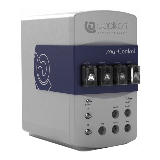
Page 11: The My-Control
Autoclavable Bioreactors 2 and 3L Hardware Version 3, Document Version 3.2 3 THE my-CONTROL The my-Control is a full-size biocontroller that is dedicated to the process in a bioreactor. It contains: • Fixed and adaptive PID control for pH, dO and Temperature •... -
Page 12: Rear View Of The My-Control
2 x T 4A (5 x 20 mm) The power switch is located at the rear side of cabinet. Make sure that the my-Control is installed in such a way, that the power switch can easily be reached in case of emergency! Optional Remote E-Stop Connector Optional connector for the external Emergency Stop circuit (button). -
Page 13: Modules To Be Mounted Inside The My-Control
In order to comply with the European EMC Standards for “emission” and “immunity”, the maximum length of the Ethernet cable is 30 meters! MODULES TO BE MOUNTED INSIDE THE my-CONTROL The following modules can be mounted inside the my-Control: Part # Description... -
Page 14: Colors Of The Front Panel
Autoclavable Bioreactors 2 and 3L Hardware Version 3, Document Version 3.2 COLORS OF THE FRONT PANEL By default, the my-Control comes with a silver front panel. Other front panel colors are available on demand. Ordering numbers of my-Controls with different colors: Part #... -
Page 15: Actuator Control
HARDWARE MANUAL THE my-CONTROL my-Control for Autoclavable Bioreactors 2 and 3L Hardware Version 3, Document Version 3.2 ACTUATOR CONTROL 3.6.1 DIGITAL ACTUATORS VERSUS CONTINUOUS ACTUATORS Discrete (digital) actuators like valves are controlled in a “Pulse-Width Modulated” manner (PWM): • within a predefined “cycle time”, the output (Actuator) is switched on during the “On-time”... -
Page 16: Sensor Input Specifications
The Redox Sensor can be used as an option (the Redox Amplifier Board is required; refer to section 3.3). It will be connected to the Level 2 sensor connection at the front of the my-Control cabinet. It in fact substitutes the Level 2 sensor. -
Page 17: Analog And Digital I/O Connections
Autoclavable Bioreactors 2 and 3L Hardware Version 3, Document Version 3.2 ANALOG AND DIGITAL I/O CONNECTIONS The analog and digital I/O connections are located at the rear of the my-Control: Analog Inputs The (max. 4) analog input connectors contain four pins: •... -
Page 18: Environmental Conditions
P-max = 400 VA 3.10 STORAGE INSTRUCTIONS When the my-Control, after being used, has to be stored for a longer time (> 1 month), follow the instructions below: • Disconnect the sensor cables and stirrer motor cable(s) from the my-Control. Store the sensors according to the instructions in the User Manual that comes with the sensor. -
Page 19: Internal Actuators
SOLENOID VALVE WITH TUNING VALVE Per gas inlet line, inside the my-Control a solenoid valve may be installed. The individual gas flows can be manually tuned by a Needle Valve Module. The needle valve module includes a Non-Return valve that prevents back-flow of gas. -
Page 20: Mass Flow Controllers
Hardware Version 3, Document Version 3.2 MASS FLOW CONTROLLERS Two types of mass flow controllers are used in the my-Control. • 3-Channel Mass Flow Controller (for controlling the flow of three individual gasses) • 1-Channel Mass Flow Controller (for controlling the flow of one gas only) Both Mass Flow Controllers (MFC) are applied for bioreactor aeration. -
Page 21: Connection For Sparging And Overlay
Z310212310* Mounting Kit for 1-Channel MFC my-Control When one or more MFCs must be added to an existing my-Control, one of the cables below must be ordered: VBL2080321* Cable Act. Board MFC (to connect the 1- or 3-channel MFC with the actuator board) VBL2080351* Cable Act. -
Page 22: Tubing Pump Assembly
Do not use the tubing pump drives for other purposes than displacement of fluids (or gas). Total number of positions for tubing pump (and micro valves) at the front of the my-Control = 4. The variable speed pump motor (0 – 200 rpm) drives a pump head. -
Page 23: Loading The Pump Tubing
4.4.1 LOADING THE PUMP TUBING WARNING: Before loading tubing into the Pump Head, switch off the power of the my-Control. Fingers or loose clothing could be caught in the rollers. 1. When the cover is opened, the Occlusion Bed moves upward, away from the rollers. -
Page 24: Pump Tubing Connection
HARDWARE MANUAL INTERNAL ACTUATORS my-Control for Autoclavable Bioreactors 2 and 3L Hardware Version 3, Document Version 3.2 4.4.2 PUMP TUBING CONNECTION The liquid addition line between storage bottle and medium inlet triple can be realized according to the image below: The rotor in the pump head turns counter-clockwise. -
Page 25: External Actuators
Dimension A (mm) Dimension B (mm) Power (W) Z311021120 Z311021130 The Heating Blanket is connected to the Heating Control Module, located at the rear of the my-Control. Refer to section 3.2 (Rear View of the my-Control) and section 3.8 (Analog and Digital I/O Connections). -
Page 26: Cold Water Valve And Condenser Regulator Valve
HARDWARE MANUAL EXTERNAL ACTUATORS my-Control for Autoclavable Bioreactors 2 and 3L Hardware Version 3, Document Version 3.2 5.1.2 COLD WATER VALVE AND CONDENSER REGULATOR VALVE The Cold Water Valve module and Condenser Regulator Valve are mounted in the External Cold Water / Condenser Assembly. -
Page 27: Actuators For Mixing
HARDWARE MANUAL EXTERNAL ACTUATORS my-Control for Autoclavable Bioreactors 2 and 3L Hardware Version 3, Document Version 3.2 ACTUATORS FOR MIXING Three different stirrer types can be used for mixing: • The Stepper Stirrer Motor, • The Brushless DC Motor M10 or •... -
Page 28: Stepper Stirrer Motor
The stepper stirrer motor is driven by the same controller as the stepper stirrer for the 250 and 500 ml MiniBio reactors. If applicable, the my-Control may be switched as controller for the MiniBio reactors to the 2 and 3L reactors and vice versa. -
Page 29: Brushless Dc Stirrer Motor M10
When during operation the control cable USB Connector is disconnected from the my-Control, the stirrer motor cannot receive a new stirrer speed setpoint. As a result, the stirrer will continue to run a the same speed until the USB connector is reconnected or the my-Control power is switched off. -
Page 30: Brushed Dc Stirrer Motor P100
The P100 is a brushed DC stirrer motor that can be used as an alternative for the M10 stirrer motor (see previous section). An encoder, present in the motor, is used for stirrer speed feedback to my-Control. The stirrer motor is delivered with four motor studs to fit in the stirrer assembly and a covered (flexible) coupling fork to avoid noise and vibrations during operation. -
Page 31: Reactors And Auxiliaries
HARDWARE MANUAL REACTORS AND AUXILIARIES my-Control for Autoclavable Bioreactors 2 and 3L Hardware Version 3, Document Version 3.2 6 REACTORS AND AUXILIARIES This chapter describes the 2 and 3L autoclavable bioreactors with their auxiliaries. REACTOR TYPES Materials in contact with the medium (all reactors): •... -
Page 32: Liter Dished Bottom Reactor
HARDWARE MANUAL AUXILIARIES my-Control for Autoclavable Bioreactors 2 and 3L Hardware Version 3, Document Version 3.2 6.1.2 3 LITER DISHED BOTTOM REACTOR Reactor type 3 liter, dished bottom Inner diameter 130 mm Inner height (maximum) 250 mm Liquid height (working volume) -
Page 33: Stirrer Assemblies
HARDWARE MANUAL REACTORS AND AUXILIARIES my-Control for Autoclavable Bioreactors 2 and 3L Hardware Version 3, Document Version 3.2 STIRRER ASSEMBLIES For agitation, stirrer assemblies, impellers and baffles can be applied. Use the formulas in section 6.2.5 determine which devices are optimal for your application. -
Page 34: Baffles
HARDWARE MANUAL AUXILIARIES my-Control for Autoclavable Bioreactors 2 and 3L Hardware Version 3, Document Version 3.2 6.2.3 BAFFLES Baffles are used to increase the mixing efficiency. Without baffles, the medium flow can become laminar, causing poor mixing efficiency and mass transfer. -
Page 35: Optimum Impeller Configuration
HARDWARE MANUAL REACTORS AND AUXILIARIES my-Control for Autoclavable Bioreactors 2 and 3L Hardware Version 3, Document Version 3.2 6.2.4 OPTIMUM IMPELLER CONFIGURATION The following images show the advised impeller configuration (position and diameter) for the glass autoclavable bioreactors (microbial and cell culture):... -
Page 36: Calculations Of Stirrer Power Requirements
HARDWARE MANUAL AUXILIARIES my-Control for Autoclavable Bioreactors 2 and 3L Hardware Version 3, Document Version 3.2 6.2.5 CALCULATIONS OF STIRRER POWER REQUIREMENTS The power (Watt) of the stirrer motor that is required depends on the number, type and diameter of the impellers, density of the medium and the stirrer speed. -
Page 37: Aeration
HARDWARE MANUAL REACTORS AND AUXILIARIES my-Control for Autoclavable Bioreactors 2 and 3L Hardware Version 3, Document Version 3.2 AERATION 6.3.1 GAS IN-/OUTLET FILTER The bacterial air filter is an economical filter for sterile gas delivery and venting applications. The hydrophobic PTFE filter membrane excludes the risk of contamination. The filter is autoclavable. -
Page 38: Air Overlay Assembly
Air overlay assembly 2 and 3 liter 10 mm port 6.3.4 PRESSURE RELIEF VALVE It is advised to install a relief valve in the (glass) Applikon reactors. The relief valve opens at a pressure of 0.5 barg. Z811302051 Pressure relief valve... -
Page 39: Air Outlet Condenser
HARDWARE MANUAL REACTORS AND AUXILIARIES my-Control for Autoclavable Bioreactors 2 and 3L Hardware Version 3, Document Version 3.2 6.3.5 AIR OUTLET CONDENSER Working at elevated temperatures and using aeration of the culture might cause too much evaporation during fermentation, causing an increase of nutrient concentration and a decrease in volume. An air-outlet condenser can prevent this. -
Page 40: Addition
HARDWARE MANUAL AUXILIARIES my-Control for Autoclavable Bioreactors 2 and 3L Hardware Version 3, Document Version 3.2 ADDITION During preparation and while running a process, fluids will be added to the reactor for medium addition, inoculation, pH and level control, perfusion, etc. -
Page 41: Medium Inlet Triple
HARDWARE MANUAL REACTORS AND AUXILIARIES my-Control for Autoclavable Bioreactors 2 and 3L Hardware Version 3, Document Version 3.2 6.4.3 MEDIUM INLET TRIPLE The medium inlet triple allows you to equip one head plate port with three additions (e.g. for acid, alkali and anti-foam addition). -
Page 42: Rapi-Lok Sterile Connector
HARDWARE MANUAL AUXILIARIES my-Control for Autoclavable Bioreactors 2 and 3L Hardware Version 3, Document Version 3.2 6.4.5 RAPI-LOK STERILE CONNECTOR The autoclavable Rapi-Loks are a fast and reliable way to make or break tubing connections during a fermentation or cell culture process. -
Page 43: Sampling And Drain
HARDWARE MANUAL REACTORS AND AUXILIARIES my-Control for Autoclavable Bioreactors 2 and 3L Hardware Version 3, Document Version 3.2 SAMPLING AND DRAIN The 1 liter reactor is delivered with a sample pipe that is fixed in the head plate. 6.5.1 ASSEMBLY HOLDER The Assembly Holder accepts any 6 mm (OD) tube. - Page 44 HARDWARE MANUAL AUXILIARIES my-Control for Autoclavable Bioreactors 2 and 3L Hardware Version 3, Document Version 3.2 6.5.2.3 SAMPLE PIPE FOR SCREENS If a sample screen is used at the end of this pipe, cell-free samples can be drawn from the culture.
- Page 45 HARDWARE MANUAL REACTORS AND AUXILIARIES my-Control for Autoclavable Bioreactors 2 and 3L Hardware Version 3, Document Version 3.2 6.5.2.6 CHEMOSTAT TUBE The chemostat tube is used in continuous fermentation. This device is designed to achieve a constant volume level in the reactor.
-
Page 46: Sample Systems
HARDWARE MANUAL AUXILIARIES my-Control for Autoclavable Bioreactors 2 and 3L Hardware Version 3, Document Version 3.2 6.5.3 SAMPLE SYSTEMS Reusable Sample system The sample system with a 60 ml (or 30 ml) glass bottle can be mounted onto the head plate of the reactor. -
Page 47: Heat Exchanger
HARDWARE MANUAL REACTORS AND AUXILIARIES my-Control for Autoclavable Bioreactors 2 and 3L Hardware Version 3, Document Version 3.2 HEAT EXCHANGER The 1 liter reactor comes with a heat exchanger that is fixed in the head plate. Heat exchanger for the 2 and 3 liter reactors:... -
Page 48: Thermometer Pocket
HARDWARE MANUAL AUXILIARIES my-Control for Autoclavable Bioreactors 2 and 3L Hardware Version 3, Document Version 3.2 G3/4” Ports Two nipples are available to fit a sensor or other OD 12 mm device with a fixed or adjustable height to the G3/4"... -
Page 49: Sensors
HARDWARE MANUAL SENSORS my-Control for Autoclavable Bioreactors 2 and 3L Hardware Version 3, Document Version 3.2 7 SENSORS Z001023551 Sensor pH+ (annular junction) L = 235 mm 2 and 3 liter PG 13.5 Z100065010 Cable pH sensor L = 0.65 m... -
Page 50: Start-Up Kit
HARDWARE MANUAL START-UP KIT my-Control for Autoclavable Bioreactors 2 and 3L Hardware Version 3, Document Version 3.2 8 START-UP KIT The Start-Up Kit for the 2 and 3L bioreactors is described below. Z81100AK12 Start-Up Kit II for autoclavable reactors 2 and 3L...
Need help?
Do you have a question about the my-Control and is the answer not in the manual?
Questions and answers