Subscribe to Our Youtube Channel
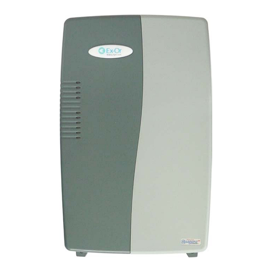
Summary of Contents for Ex-Or MLSUCA MK2
- Page 1 MLSUCA MK2 INSTALLATION GUIDE Doc:50054519-001 Rev. B Ex-Or, Novar ED&S Ltd Haydock Lane, Haydock, Merseyside, WA11 9UJ...
- Page 2 Doc:50054519-001_B...
-
Page 3: System Overview
As a controller/web-page server exclusively for the Ex-Or MLS System it is able to control and display up to 700 lighting zones spread over a number of Ex-Or RB2000/MLS Bus served areas of a building or campus. With the inclusion of the BACnet capability it is able to serve 450 lighting zones. -
Page 4: Technical Data
Preparing the MLSUCA MK2 for Fixing The MLSUCA MK2 should be mounted on a rigid surface with its long axis vertical and the two screw mounting tabs at the bottom. This allows a proper flow of cooling air through the enclosure. - Page 5 Fig. 1. Right Cover Removal. Fig. 2. Location and removal of knock-outs Doc:50054519-001_B...
- Page 6 See Fig 4. In either case the mains cabling should not be allowed to pass through the main cable chamber of the MLSUCA MK2 enclosure. After connecting the mains supply cables replace the shield over the mains terminal block. If the mains cables have been routed through the oval knock-out a blanking plug should be inserted into the circular cut out.
- Page 7 MLSUCA MK2 to terminate the two RS485 buses if the MLSUCA MK2 is to be the last device on one end of the bus. However if the MLSUCA MK2 is to be connected with at least one RB2000 between it and each of the ends of the Spine bus lines, then these resistors must be discarded.
-
Page 8: Network Connection
If, after applying power, the STATUS LED goes out, or if the yellow BEAT LED comes on (steady) and stays on for longer than two minutes, power the MLSUCA MK2 down and seek technical assistance. Documenting the wiring plan The next stage after installing the unit is commissioning.


Need help?
Do you have a question about the MLSUCA MK2 and is the answer not in the manual?
Questions and answers