Subscribe to Our Youtube Channel
Summary of Contents for Ex-Or MLSUCB
- Page 1 MLSUCB INSTALLATION GUIDE Doc: 50086856-001 Rev. D Honeywell Ex-Or Albery House, Springfield Road, Horsham, West Sussex, RH12 2PQ Tel: +44 (0)1942 719229 Web: www.ex-or.com...
- Page 2 This page intentionally left blank Doc: 50086856-001_D...
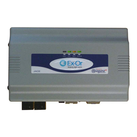
- Page 3 Ex-Or Digital Managed Lighting Systems, (MLS Systems). It also has the capability of presenting its status information and receiving commands in BACnet protocol form. The MLSUCB has two major components - the MLSJC6 and MLSJC6PSU which may also be ordered separately.
-
Page 4: Enclosure Mounting
Affixing the enclosure to the wall The MLSUCB enclosure can be wall mounted by fixing the wall mounting lugs to the corner holes on the rear side as shown in the fig.1 below. The wall mounting lugs and the fixing instructions are supplied with the enclosure. - Page 5 Fig. 2. Wiring connections to and from MLSJC6PSU Wiring the MLS Spine The MLSUCB assumes the role of Bus Master on the RB2000 Spine. This means that all the RB2000s should be given consecutive, unique non-zero addresses. The last unit at each end of the chain should be configured to terminate the two RS485 signal pairs, A-B and Y-Z.
- Page 6 Fig. 4. Spine connections from MLSJC6 to Terminal Block Fig. 5. Connection to the RB2000 Spine. Doc: 50086856-001_D...
-
Page 7: Din Rail Mounting
DIN Rail mounting The MLSJC6 and MLSJC6PSU can be individually ordered for mounting on a DIN rail. Mounting the MLSJC6 and MLSJC6PSU on the DIN rail The MLSJC6 unit base has a moulded DIN rail slot and a locking clip. A 35mm wide DIN rail is required for mounting the MLSJC6 and MLSJC6PSU. -
Page 8: Power Up And Initial Checkout
The MLSJC6 is powered by MLSJC6PSU which is a DIN rail Power supply unit. The MLSJC6PSU converts mains AC voltage to 15VDC for powering the MLSUCB. The screw type terminals for the Mains connections are on the bottom side and the 15VDC connections on the top side. The cable for the power supply connection from MLSJC6PSU to MLSJC6 is supplied along with the MLSJC6PSU module. - Page 9 Zone identities. Such as room names or numbers LCM locations Emergency Ballasts Some of this information may only be available from those who commission the MLS lighting control system which may or may not be an Ex-Or commissioning Engineer. Doc: 50086856-001_D...
- Page 10 When utilised for lighting control and lighting status display application (i.e. no emergency testing) the MLSUCB takes the role of bus master on the RS485 spine linking a number of RB2000s each of which drives an MLS bus capable of supporting up to 100 separate lighting zones comprised of up to 200 individual presence detectors with photocells.
- Page 11 System Overview- MLSUCB Doc: 50086856-001_D...
- Page 12 MLSUCB Technical Data Construction: Plastic, DIN rail or screw mount chassis, plastic cover Dimensions: MLSJC6 - 104mm (H) x 181mm (W) x 63.5mm (D). MLSJC6PSU –90mm (H) x 22mm (W) x 100mm (D) Power supply: 100-240VAC 0.55A ~ 50-60Hz universal PSU.


Need help?
Do you have a question about the MLSUCB and is the answer not in the manual?
Questions and answers