Advertisement
Quick Links
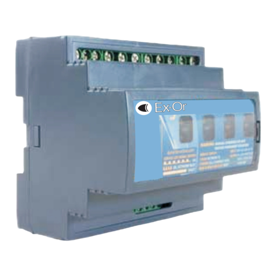
SceneSelect II
Scene-setting and Dimming System
SRC420
RELAY CONTROLLER
Warning ............................................................. 2
Features ............................................................ 2
Important Safeguards ........................................ 2
Electrical Diagram .............................................. 3
Tel: 01942 719229 Fax: 01942 272767 Email: technicalsales.ex-or@ex-or.com
Instruction Manual
Haydock Lane, Haydock, Merseyside WA11 9UJ
www.ex-or.com
Contents
Installation Steps................................................. 3
Connecting Serial Control Cables....................... 4
Product Specifications ...................................... 4
Ex-Or
W4380B
Advertisement

Subscribe to Our Youtube Channel
Related Manuals for Ex-Or SceneSelect II SRC420

Summary of Contents for Ex-Or SceneSelect II SRC420
- Page 1 Warning ............. 2 Installation Steps..........3 Features ............2 Connecting Serial Control Cables....... 4 Important Safeguards ........2 Product Specifications ........4 Electrical Diagram ..........3 Ex-Or Haydock Lane, Haydock, Merseyside WA11 9UJ Tel: 01942 719229 Fax: 01942 272767 Email: technicalsales.ex-or@ex-or.com www.ex-or.com...
- Page 2 THIS DEVICE TO RAIN OR via a computer. Should programming be MOISTURE. required, contact Ex-Or for details. Once the DO NOT ENERGISE UNLESS THE data cable is connected to the device(s), the FRONT COVER IS IN PLACE. factory default settings will allow any control THIS DEVICE MUST BE EARTHED.
- Page 3 Electrical Diagram Control Supply: 230V 0.1A 1 Phase RS485 SceneSelect II Bus Installation Steps Mount the device on a DIN rail inside an approved enclosure. Calculate loads to ensure individual channels are not overloaded, then connect loads to the output channels.
- Page 4 Connecting Serial Control Cables Connect Data Cable in a "Daisy Chain" Serial Cable Permanent Connections Sample Colours INSTALLATION DETAILS INSTALLATION DETAILS INPUT: 230 V 50-60Hz 10 A INPUT: 230 V 50-60Hz 10 A OUTPUT: 1 x 230V 10A OUTPUT: 1 x 230V 10A ORANGE/WHITE PAIR MOUNT VERTICALLY MOUNT VERTICALLY...
Need help?
Do you have a question about the SceneSelect II SRC420 and is the answer not in the manual?
Questions and answers