
Related Manuals for VELMEX VXC-1


Summary of Contents for VELMEX VXC-1
- Page 1 VXC M ICROSTEPPING OTOR ONTROLLER RIVER User’s Manual n r ller r er “Positioning Systems for Science and Industry” Since 1967 ELMEX Version 5.01 Document #UMVXC-7-23-24 Copyright 2024 INC.
-
Page 2: Table Of Contents
Jog Mode ..............................20 Optional Joysticks ........................... 20 Serial Communication ..........................21 Units & Direction ............................22 Units for Velmex Positioners ........................23 Unit Conversion........................... 23 Other Formulas ..........................23 Motion Commands ............................. 24 The Difference Between Incremental and Absolute Indexes ..............24 Incremental: I1M1000, ........................ - Page 3 Interactive Mode............................33 Interactive Examples ..........................34 Standalone Mode ............................35 Standalone Examples ..........................36 Command Summary (Common & Advanced) ..................... 37 Operation Commands ..........................37 Editing/Debugging Tools ......................... 37 Setup Commands ............................ 37 Status Request Commands ........................38 Motion Commands ..........................38 Program Management Commands ......................
- Page 4 Wait for Input ............................50 Input 1 ..............................50 Run Low/High ............................52 Conditional Branch on Input ....................... 52 Wait for Front Panel Button ........................ 52 Output ..............................53 Output 1 .............................. 53 Output 2 .............................. 53 Output 3 .............................. 53 Output 4 ..............................
- Page 5 User Input Mode ............................. 63 Motor Jog Function ..........................63 Troubleshooting ............................64 Technical Specifications ..........................66 Environmental Requirements ......................... 66 Model VXC-1 ............................66 Function .............................. 66 Physical..............................66 Cabling ..............................66 Electrical Requirements ........................66 I/O ............................... 66 Serial Ports ............................
- Page 6 Appendix A (Motor Settings) ........................69 Setting Motor Type ..........................69 Non-Standard Motors ......................... 70 Appendix B (Limits/Home/Stall Detect) ...................... 71 Limit Switch Inputs ..........................71 Home/Stall Detect Input ......................... 72 Limits, Home, Stall Detect Function Interaction ..................73 Device Compatibility with Limits, Home, Stall Detect ................ 73 Using a Limit for Home Reference ......................
- Page 7 Analog Joystick (2 Axis Finger Stick) ....................86 VC Series Analog Joystick (2 & 3 Axis) ....................87 Appendix F (Faults) ............................. 88 Fault Checking ............................88 Immediate Checks ..........................88 Level 1 Faults ............................89 Level 2 Faults ............................89 Level 3 Faults ............................
- Page 8 Complex Profiles/Coordinated Motion ....................105 Complex Profiles ..........................105 Coordinated Motion ......................... 105 Master/Slave Associated Programs ....................106 Appendix M (Math) ........................... 107 Math Capability ............................. 107 Math Expressions ..........................108 “if” Conditional Statement ........................ 109 “if” Expressions ..........................109 “end”...
- Page 9 Table 1 When VXC Will not be Factory Configured ..................19 Table 2 Settings for Limits, Home/Stall ....................... 20 Table 3 Velmex Product Advance per Turn & Advance per Step ..............23 Table 4 Motor Type Setting ........................69 Table 5 Motor Type Setting for Legacy 6 Wire Motors (Half Winding) ............69 Table 6 “get Motor Type”...
- Page 10 Table 13 Finger Joystick Cable Connections ....................86 Table 14 VC Series Analog Joystick Connections ..................87 Table 15 Index Listing of Faults ........................92 Table 16 Controller Mode Settings ......................96 Table 17 User Inputs Mode Settings ......................98 Table 18 Program Select Truth Table ......................
- Page 11 Example 1 Enable On-Line Mode Echo on ....................44 Example 2 Single Axis Incremental Index Move 1 Motor 400 Steps ............44 Example 3 Single Axis Incremental Index Move 1 Motor 400 Steps ............44 Example 4 Clear all Commands from Current Program & Zero Motor Position ......... 44 Example 5 Clear Previous &...
- Page 12 Torque Graph 20 for VMN231-4.2-D (ST5918X3008) Motor @ 24V With Damper ......... 140 Torque Graph 21 for VMN231-4.2-D (ST5918X3008) Motor @ 24V ............140 Torque Graph 22 for VMN231-4.2-D (ST5918X3008) Motor @ 28V, 100% Power, With/Without Damper .................................. 141 Torque Graph 23 for VMN232-4.2-D (ST5918S3008-B) Motor @ 24V With Damper ......142 Torque Graph 24 for VMN232-4.2-D (ST5918S3008-B) Motor @ 24V .............
-
Page 13: Precautions
Do not disconnect motor while running. Keep Motor and Limit cables separated if possible. Only operate with designated motor. Do not alter cables in any way without first consulting Velmex CAUTION: Mismatched Motor Settings can Damage Motor & Controller... - Page 14 TO REDUCE THE RISK OF ELECTRICAL SHOCK, DO NOT ATTEMPT TO REMOVE COVERS ON POWER SUPPLY OR CONTROLLER. THERE ARE NO USER SERVICEABLE PARTS INSIDE. Any servicing should be done by Velmex qualified service personnel. ELMEX Version 5.01 Document #UMVXC-7-23-24 Copyright 2024 INC.
-
Page 15: High Integration Stepping Motor Controller/Drive
Coordinated motion to produce angles, arcs, circles, etc. Model Numbers The basic VXC model numbers are VXC-1, VXC-2, VXC-3, VXC-4 which include a 24V power supply and 10-foot motor and limit cables. Velmex will customize the VXC to your exact requitements. Different voltages, cable lengths, special labeling, optional connectors, custom remote jog controls, custom programming, and open chassis versions are some of the possibilities. -
Page 16: Function
Function Figure 1 VXC-2 Functional Diagram ELMEX Version 5.01 Document #UMVXC-7-23-24 Copyright 2024 INC. -
Page 17: External Features
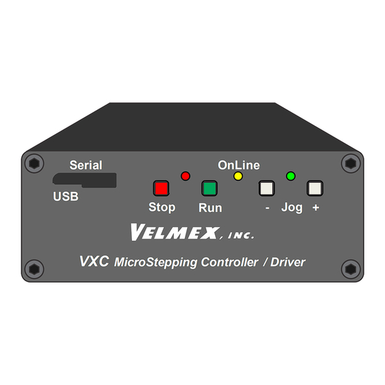
External Features e me com icroSte ing ontro er ri er Motor Leadshine Nanotec Oriental Grn & Wh/Blk Blk & Wh/Grn Blu & Wh/Red Red & Wh/Blu Pin# Name Wire Color Limit Cable (Cat5e) Limit CW (+) Wh/Or 0V (Common) Limit CCW (-) Wht/Grn +10V Output... -
Page 18: Setup
. Normally closed to move is the standard used for mechanical switches on Velmex products. Normally open to move is common for hall type limits and home switches. Velmex linear and rotary tables with the home switch option require that the switch inputs be configured correctly. -
Page 19: Configuring Vxc With Device Id
Damage to the VXC, Motor, Switches, and the Mechanical Assembly. The easiest method to enter the Device ID# into the VXC is with the Velmex VXC Utility App. The other method is using a simple terminal program and directly type in the information. Put the VXC On-line first by sending an “E”... -
Page 20: Device Id For Limit, Home/Stall Settings
Device ID for Limit, Home/Stall Settings The Device ID defines the system motor, limits, and home/stall hardware. Refer to Table 2 Settings for Limits, Home/Stall description of settings. Table 2 Settings for Limits, Home/Stall 7/5/2024 VXC Label ID# Creator for "setMLHm M=Label ID"... -
Page 21: Serial Communication
"F" so the host’s input buffer will not be burdened with echoed characters from the VXC. Use ”C” to clear previous commands from any previous command sending. The simplest method to send commands is with the Velmex VXC Utility App, or with a terminal program like TeraTerm, CoolTerm, Termite, etc. -
Page 22: Units & Direction
Direction is relative to the device the motor is used on. On screw drive actuators like UniSlide®, XSlide and BiSlide® Assemblies, positive is the direction moving away from the motor. On worm gear type rotary tables like the Velmex B4800 or B5990, positive is counter clockwise (CCW.) To reorient direction, refer to “Controller Mode“... -
Page 23: Units For Velmex Positioners
Units for Velmex Positioners Table 3 Velmex Product Advance per Turn & Advance per Step Lead Screw Models BiSlide Speed UniSlide XSlide Advance per turn Advance per step @ 1000 sps (2.5 rps) Units Units Units 0.025 inch 0.0000625 inch 0.0625 inch/sec... -
Page 24: Motion Commands
Motion Commands This section gives detailed explanations of the VXC motion commands. For the advanced user, refer to the Appendices for more information. Most commands with variables (except “set” and “get” commands) use the VXC's program memory space. The required memory needed per command is specified in the command description. The VXC has 256 bytes of program memory allocated for each program. -
Page 25: Incremental Index (Move An Increment)
Incremental Index (Move an Increment) ImMx Set steps (400 steps/rev.) to incremental Index (move) motor, m=motor# (1,2,3,4) Motor moves CW (positive, Slider/Carriage will move away from motor end, Rotary Table will rotate CCW ) when x=1 to 16,777,215. Motor moves CCW (negative, Slider/Carriage will move toward motor end, Rotary Table will rotate CW ) when x= -1 to -16,777,215... -
Page 26: Absolute Index (Move To Position)
Absolute Index (Move to Position) IAmMx Set steps (400 steps/rev.) to Absolute Index (move), m=motor# (1,2,3,4) , x=±1 to ±16,777,215 NOTE: The absolute position registers have a range of -8,388,608 to 8,388,607 steps therefore to maintain a correct absolute position x should not be set to any number less than -8,388,608 or greater than 8,388,607. -
Page 27: Index To Absolute Zero (Move To Zero)
Index to Absolute Zero (Move to Zero) IAmM0 Set an Index to Absolute zero position, m=motor# (1,2,3,4) When this command is used the VXC calculates the distance and direction to get back to absolute zero position. The "absolute zero" position was established when the "N"... -
Page 28: Move To Positive To Home/Limit
Move to Positive to Home/Limit ImM0 Move positive until Home or positive limit switch is encountered, m=motor# (1,2,3,4) Refer to Appendix B (Limits/Home/Stall Detect) for limit switch and home settings. The Index will end if the switch is not encountered after 16,777,215 steps. Memory usage = 4 bytes. -
Page 29: Speed
NOTE: Motor power will always be zero when the motor is stationary (motors are normally un- energized at a standstill. Contact the Velmex Engineering department for more information on fail-safe brake and holding torque options. NOTE: Motor torque decreases as speed increases, and some motors have limited useful torque above 3000 steps/sec. -
Page 30: How To Determine Maximum Speed
Smart Speed values are based on a maximum speed that has approximately 50% of the starting torque of the motor. Contact the Velmex Engineering department for help on determining what system parameters to consider for your particular application. -
Page 31: Acceleration
Acceleration AmMx Set Acceleration/deceleration of motor, m= motor# (1,2,3,4) , x= 1 to 127. If never set the default value will be 2. The higher the number the faster the motor will reach the set speed, and the faster it will slow down to a stop. NOTE: motors may stall if this value is set too high. Memory usage = 2 bytes. -
Page 32: Program Coding Shortcut
Controller is first turned on. The last motor jog/slewed will be the current motor number. The current motor will be the number used in the last Acceleration, Speed, or Index command. Users that have only a one motor VXC (Model VXC-1) do not have to use the motor designation in a command. -
Page 33: Interactive Mode
7. Repeat from Step #2 Figure 2 Interactive Mode Application software such as Velmex VXC Utility App TeraTerm, C, BASIC, Python, LabVIEW, MATLAB, etc. are commonly used to send, receive, wait, and repeat in Interactive Mode. Refer to examples at VelmexControls.com... -
Page 34: Interactive Examples
Interactive Examples The interactive examples below are shown keyed directly into Velmex VXC Utility App terminal window. NOTE: Spaces between commands are optional and commands with a value should end with a comma or carriage return (enter). Example that puts the VXC On-line with echo on, Clears memory, Indexes motor one 4000 steps... -
Page 35: Standalone Mode
8. Use the Run button or Run input to start the program Figure 3 Standalone Mode Application software such as Velmex VXC Utility App, TeraTerm, CoolTerm, Termite, etc. are commonly used to send/download commands. Refer to examples at VelmexControls.com When running Standalone, multiple programs (0 to 7) can be selected and run with a thumbwheel selector switch connected to Inputs 1,2,3, refer to Multifunction User Inputs and Application Note for selecting programs with a thumbwheel switch. -
Page 36: Standalone Examples
Standalone Examples The Standalone examples below are shown keyed directly into Velmex VXC Utility App terminal window. NOTE: Spaces between commands are optional and commands with a value should end with a comma or carriage return (enter). Example that saves an Index for motor one of 4000 steps in Program #0... -
Page 37: Command Summary (Common & Advanced)
Command Summary (Common & Advanced) The following are the abbreviated descriptions for the most common commands, refer to the “Command Reference” section for detailed command information. Operation Commands Enable On-Line mode with echo "on" Enable On-Line mode with echo "off” Clear all commands from current program Quit On-Line mode (return to Local/Jog mode) Run currently selected program... -
Page 38: Status Request Commands
Status Request Commands Help Display context sensitive help screen (for use with terminal program interfacing) Send current position of motor 1 to host (Motor can be in motion) Send current position of motor 2 to host (Motor must be stationary) Send current position of motor 3 to host (Motor must be stationary) Send current position of motor 4 to host (Motor must be stationary) Verify Controller's status, VXC sends “F”... -
Page 39: Program Management Commands
Program Management Commands Select Program number x, x= 0 to 12 PM-x Select and clear all commands from Program number x, x= 0 to 12 Request the number of the current Program Request Memory available for currently selected program lst, List the current program for a single axis VXC lstmMx List program x of axis m Run save memory (saves setup &... - Page 40 Start of Continuous Index with no output Start of Continuous Index sending "@" to the host End of Continuous Index with auto-decel to stop Synchronize Master and Slave Axis End of Continuous Index with auto-generate a deceleration Index as next command End of Continuous Index using next Index for deceleration to stop End of Continuous Index with instantaneous stop Skip next command if input 1 is high...
-
Page 41: Program Management Commands
U219 Axis 4 User output 4 high Program Management Commands Most commands with variables (except set commands) use the VXC's program memory space. The required memory needed per command is specified in this section. The VXC has 256 bytes of program memory for each program. - Page 42 Run save memory, saves setup/ program values to nonvolatile memory. The VXC will send the single character "^" after completion of the save. Use this command to: 1. To permanently save setup/special function (commands) values that have been modified. 2. To save programs/commands and settings for stand-alone use. CAUTION: When using the “rsm”...
-
Page 43: Editing/Debugging Tools
Editing/Debugging Tools Ignore all characters from here to end of the line (<cr>) Used to add comments in script files to send to the VXC. Example: ;Put VXC On-Line with Echo Off ;Clear Out All Previous Commands I1M400, ;Index Motor 1 400 steps+ (1 rev) The VXC only interprets the “FCI1M400,”... -
Page 44: Program Examples
Program Examples The following examples can be keyed into the VXC with a terminal program like TeraTerm, or the Velmex VXC Utility App. Another method to send commands is with commercially available languages such as BASIC, C, LabVIEW, Matlab, etc. -
Page 45: Example 5 Clear Previous & Index Move 2Nd Motor 600 Steps
NOTE: Running Multi-Axis examples on a VXC that lacks an axis will result in Fault # 31 “Axis Does Not Exist” Example 5 Clear Previous & Index Move 2nd Motor 600 Steps C I2M-600,R Bytes: 4 ← End|------------|Start Example 6 Index Motor 1 Both Directions (Auto Reverse) C I1M800,I1M-800,R Bytes: 8 →... -
Page 46: Example 10 Two-Axis Raster Scan With 0.1 Pulse At Each Stop & Return To Start
Example 10 Two-Axis Raster Scan With 0.1 Pulse at Each Stop & Return to Start N C I1M300,PA.1,L7,I2M400,L-4,IA2M0,R Bytes: 21 → P Start0---|---|---|---|---|---|---| : ↓ P ← : |---|---|---|---|---|---|---| : ↓ : → P |---|---|---|---|---|---|---| : ↓ P ← : |---|---|---|---|---|---|---| Example 11 Two-Axis With Two Different Raster Scans &... -
Page 47: Example 12 Three-Axis Xy Matrix, Z Up/Dn At Each Position, & Return To Start
NOTE: Running Multi-Axis examples on a VXC that lacks an axis will result in Fault # 31 “Axis Does Not Exist” Example 12 Three-Axis XY Matrix, Z up/dn at Each Position, & Return to Start NC I3M1000,I3M-1000,I1M600,L5,I2M400,L-3,(IA2M0,IA1M0,)R Bytes: 32 → Start0-----|-----|-----|-----| : ↓... -
Page 48: Looping/Branching Commands
Looping/Branching Commands Loop Loop continually from the beginning or Loop-to-marker of the current program. The loop will occur to the last Loop-to-marker of the current program if it was set previously. This command can be used once in a program as the last command, it functions the same as a "continuous run input". -
Page 49: Jump
LA-x Loop Always from beginning or Loop-to-marker of the current program x-1 times alternating direction of motor 1 indexes (x=2 to 65,535). Maximum 10 nested loop commands per run allowed. Memory usage = 3 bytes Examples: This example sets a loop to repeat all previous commands 100-1 times: LA100<cr> Consecutively nested loops are equal to the product of their loop values. -
Page 50: Pause
Pause Pause x seconds, (x=0.0001 to 5.9999 & 6.0 to 6553.5 seconds) Memory usage = 3 bytes Examples: This example pauses for 50 milliseconds: P.05<cr> This example pauses for 0.6 seconds: P.6<cr> This example pauses for 10 seconds: P10<cr> This example pauses for 1.25 seconds: 1.25<cr> This example pauses for 1 hour: P3600<cr Pause x seconds (x=0.0001 to 5.9999 &... - Page 51 Wait for a low to high transition on the user input 1. A "high" is a voltage between +1.5VDC and +5VDC applied to I/O,5. A simple pushbutton or toggle switch can be used between 0V (I/O,1) and input 1 (I/O,5) to satisfy this input. The input level must be low (less than 0.8V) for at least 1ms, and go high for at least 1 ms to be a valid input.
-
Page 52: Run Low/High
Run Low/High Wait for a low to high transition on the Run input/button with debouncing for a mechanical push-button switch. Pressing the front panel Run button or a connection between I/O,4 and I/O,1 (0V) will activate this input. Memory usage = 2 bytes Programming Tip: Use “U90“as the first command if you want a run to only start with a press and the release of the Run button. -
Page 53: Output
Output Output 1 User output 1 low. The user output 1 (I/O,14) will go to 0V. This is the state of the user output 1 on power-up. This command is used in conjunction with the "U5" command. Memory usage = 2 bytes User output 1 high. -
Page 54: Outputs On Axes 2,3,4
Outputs on Axes 2,3,4 The I/O outputs on a second, third, or fourth Slave VXC (in a Master/ Slave bussed configuration) are available through the Master. To access the user I/O on the Axis 2 from the Master use the standard “Ux”... -
Page 55: Jog While Waiting
Jog While Waiting Enable Jog while waiting for an input. This command will allow motor jogging, with the jog button/inputs, during the following wait commands: U0, U1, U30, U31, U50, U51, or U90 Memory usage = 2 bytes Disable Jog while waiting for an input (default setting on power-up.) This command will disable motor jogging during a wait command. - Page 56 End of Continuous Index. This command is similar to the “U9” except it requires an index move directly after it in the program for decelerating to a stop. When the VXC sees this command, it will look ahead for the index command and use it as the deceleration distance. Memory usage = 2 bytes NOTE: The “U91”...
-
Page 57: Operation Commands
Operation Commands NOTE: These commands are immediate (not stored), they do not use the VXC's program memory, and do not need an ending carriage return or comma. Online/Off-Line Enable On-Line mode with echo on. The single character "E" is used to put the VXC in the On- Line mode after power-up. -
Page 58: Status Request Commands
Status Request Commands Help Menu Help Display context sensitive help screen (for use with terminal program interfacing) Sending “Help” to the VXC will list the most basic commands pertinent to the current mode the Controller is in. Help Menu in Jog Mode VXC Jog Mode Commands =Status: J=Jog,b=Busy =Enable OnLine echo on... -
Page 59: Verify Status
Send position of motor 4 to the host. When the VXC receives the single character "T" it will transmit the value from its motor 4 Absolute Position Register. This is what the host would receive if motor 4 is at positive 930005: 0930005<cr> Motor must be stationary. -
Page 60: Position When Decelerated
Position When Decelerated (Asterisk) Request motor position when the last deceleration occurred. This position can be from a normal index decelerating to a stop, or an interrupted index from a "D" (Decelerate to a stop) command or Stop input/button (User input 4.) Below is what the host would receive if the last motor indexing started its deceleration at position negative 14901. -
Page 61: List All Settings
NOTE: The VXC also sends the ASCII character <EOT> (End-Of-Transmission, decimal value 4) at end of listing the settings. Example listing all settings on a single axis VXC (VXC-1): lss, The default motor is the last motor selected when using the “mM” designator in a command. At power up the VXC sets the default motor to 1. -
Page 62: Backlash Compensation
Backlash Compensation getKmM Read Backlash Compensation setting for axis m, off when value returned=0 (default) The number of “comp” steps will be returned when set. See “setKmM” command for more information Motor Type getMTmM= Read motor type set for motor/axis m ... -
Page 63: Pulse Output Settings
Pulse Output Settings getPmM Read “Pulse Every x # Steps” value for axis m See “setPmM” command for more information getPA Read Pulse width used by setPmMx and U7 See “setPAmM” command for more information User Input Mode getI Read operating mode of user inputs ... -
Page 64: Troubleshooting
Troubleshooting Symptom Cause/Remedy At Power-up, Green LED flashes rapidly Jog, Run, or Stop button is down (low). Release button or input. At Power-up, Red/Green LEDs alternate flash Wrong power supply voltage, verify power supply constantly is 24VDC At Power-up, Red+Yellow/Green LEDs alternate Internal fuse issue. - Page 65 Symptom Cause/Remedy Motor vibrates excessively between 100 and 2000 Wrong motor setting or power is too high for steps per second load. Use 40% power (S-x for speed) if light to no load application. Motor vibrates excessively between 2000 and 3000 Wrong motor setting or power is too high for steps per second load.
-
Page 66: Technical Specifications
Technical Specifications Environmental Requirements Ambient Operating Temperature: 35°-95° F (2°-35° C) Relative Humidity: 10%-90% (non-condensing) Model VXC-1 Function One Axis Motor Controller with Half-step/Micro-step 31.25 kHz PWM motor drive for size 11 to 34 hybrid stepping motors. Physical Weight: 1.3 lbs (0.57 kg) Height (without feet): 1.5”... -
Page 67: Model Vxc-2
Width: 3.90” (99.1 mm) Length: 4.42” (112.3 mm) Cabling, Electrical Requirements, I/O, Serial Ports Same as VXC-1 Except 2x Power and Cabling Model VXC-3 Function Three Axis Motor Controller with Half-step/Micro-step 31.25 kHz PWM motor drive for size 11 to 34 hybrid stepping motors. -
Page 68: Power Supply
Stepping Motor Controllers manufactured by Velmex are warranted to be free from defects for a period of two (2) years on all parts. Velmex's obligation under this warranty does not apply to defects due, directly or indirectly, to misuse, abuse, negligence, accidents, or unauthorized repairs, alterations, or cables/connectors that require replacement due to wear. -
Page 69: Appendix A (Motor Settings)
Use the setMTmM=a to set the motor(s) for each axis m to value “a” in Table 4 Motor Type Setting. IMPORTANT: Always use “rss” command after set to permanently save Table 4 Motor Type Setting Motor Model (base Velmex Catalog Number Smart Speed (shortcut) (long) -
Page 70: Non-Standard Motors
Maximum product of Inductance & Amps: Maximum L (Mh) x I (Amps) = 12 CAUTION: Incorrect Motor Settings can Damage VXC and Motor Contact Velmex technical support at Support@Velmex.com for correct setting for motors not listed in Table 4 Motor Type Setting & Table 5 Motor Type Setting for Legacy 6 Wire Motors (Half Winding) ELMEX Version 5.01 Document #UMVXC-7-23-24... -
Page 71: Appendix B (Limits/Home/Stall Detect)
Appendix B (Limits/Home/Stall Detect) Limit Switch Inputs The VXC by default recognizes both normally closed (N/C to run) and normally open (N/O to run) limit switches, this is the auto-detect mode for limit switches. CAUTION: In auto-detect mode, If the device is on (actuating) one of the limits at power-up the Limit switch mode should VXC will not know for certainty if the switches are N/C or N/O type. -
Page 72: Home/Stall Detect Input
The VXC has a dedicated Home/Stall input that can be configured several different ways. When used as a dedicated home input it allows the limit switches to coexist with a home input. Verification of motor position is possible if the input is used with the Velmex stall detect option on the motor The “setHSx”... -
Page 73: Limits, Home, Stall Detect Function Interaction
Limits, Home, Stall Detect Function Interaction Since the VXC inputs are multifunctional, some functions conflict with each other and home settings will override limit settings. There are two different places to connect a home switch, to limit switch inputs tied together or to the dedicated Home Input. Table 9 Limit, Home, Stall Settings Interaction shows the interaction of the limit, home, and stall functions. -
Page 74: Using A Limit For Home Reference
Using a Limit for Home Reference When a dedicated home switch is not possible or necessary, like when the optional stall detect is needed, the limit switches can be utilized as a home reference. Programming sequence for homing to a limit switch 1. -
Page 75: Using A Home Switch On Home Input
Using a Home Switch on Home Input When properly applied, a home switch provides a high degree of precision and accuracy as an absolute starting reference. Repeatability of 1 motor step is achievable if the proper procedures are followed when referencing to a home switch. For a hall effect or reed type switch use “... -
Page 76: Example 17 Move Positive Into Home Switch And Zero Position 1000 Steps Away
This example homes motor 2 moving positive direction into home switch and zeroes position 1000 steps away from switch. Example 17 Move positive into home switch and zero position 1000 steps away C S2M800,I2M0,I2M-4000,I2M0,I2M-1000,IA2M-0,R Bytes: 23 → Start, Index to Home|--------------------|Stopped by Home Switch ←... -
Page 77: Appendix C (Referencing/Feedback)
Limit or Home Switch for Initial Reference The limit switches or an optional home switch on a typical Velmex assembly can provide an absolute position reference with a repeatability of better than 0.0004” (0.010 mm.) Referencing a limit or home switch after initial power-up is the simplest method to insure consistent repeatability from a precision positioning system. -
Page 78: Backlash Compensation Set Examples
Backlash Compensation Set Examples This example sets the backlash compensation on motor 2 to 1 (20 steps): setK2M1<cr> This example sets the backlash compensation on motor 1 to 30 steps: setK1M30<cr> This example disables backlash compensation on motor 3: setK3M0<cr> IMPORTANT: Always use “rss”... -
Page 79: Appendix D (Digital Jog)
Appendix D (Digital Jog) Advanced Digital Jog Mode When the On-Line (yellow) light is not lit, the VXC is in the Local/Jog mode. Using the front panel jog buttons, each motor can be jogged a single step or slewed to a default speed of 2000 sps (5 revs/sec.) in either direction. -
Page 80: Optional Digital Joystick
Optional Digital Joystick The optional digital joystick allows remote jog control of a one or two axis VXC controller. The joystick provides four momentary outputs that are connected to the Jog Motor inputs on the Auxiliary I/O (internally connected to same inputs as the front panel jog buttons.) See Advanced Digital Jog Mode for information on jog function and speed settings. -
Page 81: Jog Function Settings
Jog Function Settings Optional Jog settings are available for how the digital jog responds to the jog buttons/inputs. There is an 8-bit value for the settings (see Table 11 Jog Function Settings) to read and write with the following commands. setMJmMx Set Motor Jog function decimal number x between 0-255, m= motor# (1,2,3,4) setMJmMb,x... -
Page 82: Custom Jog Distances
This Example will list the complete detailed Jog settings. getMJc Below is what the VXC will send back. * 76543210 Bit # # 00000000 (Default Setting) 7,#1: Slower Accel *7,#0:(------) 6,#1: Faster Accel *6,#0:(------) 5,#1: Slower Decel *5,#0:(------) 4,#1: Faster Decel *4,#0:(------) Bit#, Value: Function 3,#1: Longer Pause... -
Page 83: Appendix E (Analog/Jog)
Appendix E (Analog/Jog) Analog Input The VXC has a 10-bit analog to digital converter for general use, motor speed setting, or for use with the Analog Joystick Option The analog reference voltage is the internal +5VDC which is also used for the VXC’s internal logic. This +5VDC is brought out on I/O pin 2 for use with additional analog circuitry. -
Page 84: Analog Joystick Option
Analog Joystick Option The VXC Proportional Speed Joystick provides a precise efficient one, two, three, or four axis variable speed positioning system when used with VXC Stepping Motor Controllers. The joystick has a button switch for a primary/secondary speed range selection. Heavy duty and Joysticks without the enclosure are available for OEM applications. - Page 85 Table 12 Analog Joystick Speed Ranges Speed Range (steps/sec.) Disable joystick 1-250 2-500 3-750 4-1000 5-1250 6-1500 7-1750 8-2000 9-2250 10-2500 11-2750 12-3000 13-3250 14-3500 15-3750 16-4000 17-4250 18-4500 19-4750 20-5000 21-5250 22-5500 23-5750 24-6000 IMPORTANT: Use the ”rss” command to save new joystick settings ELMEX Version 5.01 Document #UMVXC-7-23-24 Copyright 2024...
-
Page 86: Analog Joystick (2 Axis Finger Stick)
The finger joystick provides analog outputs for two VXC axes. A connection to each axis is accomplished with a special Velmex “Y” cable. The analog joystick has a button switch connected to Input 2 for toggling between the primary and secondary settable jog speeds. -
Page 87: Vc Series Analog Joystick (2 & 3 Axis)
VC Series Analog Joystick (2 & 3 Axis) The VC series joystick provides analog outputs for two or three VXC axes. There are 10’ (3 meter) integrated cables for connection to each axis. The joystick has a center button switch on the stick connected to Input 2 for toggling between the primary and secondary settable jog speeds. -
Page 88: Appendix F (Faults)
Appendix F (Faults) Fault Checking The VXC does extensive fault checking with three levels of alarms dependent on the significance of the fault. Limit switches and the optional Stall detect allow user settable alarm levels. Additionally, Output 4 can be set as an alarm output for level 3 fatal faults. Immediate Checks At power-up the VXC checks for Run, Stop, Jog+ &... -
Page 89: Level 1 Faults
Level 1 Faults Level 1 faults are change of state faults. Level one faults log the fault only. Fault # Description Type Motor detection failure hardware Power failed (default every power up) Interrupt Stop pressed (input 4 low) Interrupt Hit limit switch Interrupt First power up after factory default Interrupt... -
Page 90: Level 3 Faults
Figure 5 Limits Connection. The removable fuse is an automotive 4-amp Mini AT size accessible by separating the top and bottom of the enclosure by first removing the screws from the front and rear panels. Before attempting fuse replacement contact Velmex technical support at Support@Velmex.com for help and the proper procedure to check or replace fuse. -
Page 91: Level 3 Faults By Common Flash Code
Level 3 Faults by Common Flash Code Master/Slave Communication Faults Fault # Description Flashing LEDs Type Lost communication with Axis 2 R:10 Y:01 G:00 hardware Lost communication with Axis 3 R:10 Y:01 G:00 hardware Lost communication with Axis 4 R:10 Y:01 G:00 hardware Slave Axis version not up to date R:10 Y:01 G:00... -
Page 92: Level 3 Faults Checked At Power-Up Only
Level 3 Faults Checked at Power-up Only Fault # Description Flashing LEDs Type Fuse blown R:10 Y:10 G:01 hardware Input voltage too low R:10 Y:00 G:01 hardware Input voltage too high R:10 Y:00 G:01 hardware Slave Axis is off R:10 Y:01 G:00 hardware Index of All Faults To see a listing of all the possible faults with their description use the indexF command. -
Page 93: Appendix G (Serial Ports)
Appendix G (Serial Ports) Serial Port Connections The VXC has two independent serial ports for communication with a host computer or PLC. One port is a USB standard port and the other is a full duplex RS-422 port that can be configured as a RS-232 compatible port. -
Page 94: How To Test Usb Cable For A Reliable Connection
Figure 12 Wiggle Test on USB Cable Velmex sells USB cables that have been evaluated and tested to provide error free communication with the VXC. Since the USB receptacle in the VXC has a durability rating of 10,000 cycles, any connection failures are most likely due to the cable. -
Page 95: Rs-422 Adapters
RS-422 Adapters There are optional RS-422 Breakout cables and a RS-422 to RS-232 Adapter/Converter cables available from Velmex. Figure 14 RS-422 to Terminal Block Breakout Figure 15 RS-422 to RS-232 Adapter/Converter Only RS-232 receivers that accept 0-5VDC on Rx as valid data are compatible with this adapter ELMEX Version 5.01 Document #UMVXC-7-23-24... -
Page 96: Appendix H (Modes)
Appendix H (Modes) Controller Mode The VXC has a main mode register that can be set with the “setDMx” command. setDMx Set operating mode of VXC. The value for x is a number between 0 and 255 that can be derived from the table below. - Page 97 This Example will set bit 7 which will run program #12 on first Run after being powered up. setDMb7,1<cr> “getDMb<cr>” will return “10000001<cr>” “getDM<cr>” will return “129<cr>” “getDMb7<cr>” will return “1<cr>” This Example will set Mode settings back to default. setDMb,00000001<cr>...
-
Page 98: Appendix I (Inputs)
Appendix I (Inputs) Multifunction User Inputs setIx set operating mode of User Inputs. The value for x is a number between 0 and 255 that can be derived from Table 17 User Inputs Mode Settings. Example: This example enables binary selection of programs 0 to 7 with user inputs 1,2, and 3. setIb6,1<cr>... - Page 99 This Example will return current setting in binary format. getIb<cr> 00000111<cr> VXC will send: This Example will return Run enable/disable bit setting. getIb0<cr> 1<cr> VXC will send: This Example will list the complete detailed Mode settings. getIc Below is what the VXC will list back. * 76543210 Bit # # 00000111...
-
Page 100: Appendix J (Dynamically Read Position)
Appendix J (Dynamically Read Position) Getting Motor Position When Moving Motor position can be directly read while motor is in motion on Axis 1 using the “X” command. At high motor speeds serial port latency will result in miss reading the actual position. Another approach is to use an external trigger to tell the VXC to capture motor position(s) for later retrieval (after motion has ended.) The Automatic Deceleration Capture... -
Page 101: Appendix K (Output Triggers)
Appendix K (Output Triggers) Producing Trigger Outputs There are three different methods to produce a trigger pulse, at exact positions, commonly used for signaling data acquisition equipment. 1. Index to a position, then while stopped use “PA”, “U1”, or “U5”/” U4” command. 2. -
Page 102: U7 Continuous Indexing Command Examples
U7 Continuous Indexing Command Examples This example makes an index on motor 1, producing a pulse at positions 1000,1100,1150,1250, and then runs motor 1 back to the start position: S1M1500,U7,I1M1000,I1M100,I1M50,I1M100,U9,IA1M0<cr> This example will Index motor 1 and pulse 100 times: U7,I1M400,LA100,U9<cr>... -
Page 103: Pulse Every "N" Steps
Pulse Every “n” Steps The following commands make it possible to produce a pulse at a fixed interval of motor steps from 1 to 32,767. setPmMn Set “Pulse Every n # Steps” on Output 2 for axis m, m= motor# (1,2,3,4), n= 0 to 32,767 (0= disable/default.) Pulse width is settable with the “setPAx”... - Page 104 getPmM Get value for “Pulse Every n # Steps” for axis m. m= motor# (1,2,3,4) Value returned will between 0 and 32,767 (0= disabled/default) setPAx Set Pulse width used by setPmMn and U7 commands. x= 1 to 255 (1=default.) Units are 10µsec increments (10 x 10 seconds) Example:...
-
Page 105: Appendix L (Complex Motion)
Appendix L (Complex Motion) Complex Profiles/Coordinated Motion Complex Profiles The VXC automatically does a simple profile move every time it is required to perform an index. This profile consists of an acceleration segment, slew segment, and a deceleration segment. Using the VXC’s Continuous indexing feature more complex motion profiles are possible. -
Page 106: Master/Slave Associated Programs
Master/Slave Associated Programs Multi-axis VXC models can be set to run programs, residing in each axis, simultaneously. The procedure to coordinate VXC axis programs to VXC axis programs is as follows. 1. Transfer a program(s) to a Slave Axes using “[m[…]” 2. -
Page 107: Appendix M (Math)
Appendix M (Math) Math Capability The VXC can perform basic arithmetic operations of addition, subtraction, multiplication and division. Arithmetic capability allows for: 1) Setting & proportioning speed to analog input value 2) Producing custom asymmetrical accelerations / decelerations 3) Calculating position in pick & place applications 4) Self-determining center of system travel. -
Page 108: Math Expressions
Math Expressions Table 20 Math Expressions a=[literal] ImMx=a a=a+[literal] a+[literal] b=[literal] ImMx=b b=b+[literal] b+[literal] c=[literal] ImMx=c c=c+[literal] c+[literal] a=-a IAmMx=a a=a-[literal] a-[literal] Shorthand b=-b IAmMx=b b=b-[literal] b-[literal] Equivalent c=-c IAmMx=c c=c-[literal] c-[literal] a=-b a=a*[literal] a*[literal] a=-c SmMx=a b=b*[literal] b*[literal] b=-a SmMx=b c=c*[literal] c*[literal]... -
Page 109: If" Conditional Statement
“if” Conditional Statement The VXC can perform the statement “if” in the following format. if <expression> True=do next/False=skip next When “if” is encountered in a program the next command will be skipped if the result is False (performs next command if True) “if”... -
Page 110: Setting & Proportioning Speed To Analog Input
Setting & Proportioning Speed to Analog Input The VXC has a 10-bit analog to digital converter for general use, motor speed setting, or for use with the optional Analog Joystick. Example 21 Setting Speed Proportional to Analog Input Description Motors Run Function Analog Speed Set speed 1 to 4000 proportional to the value of the analog input... -
Page 111: Producing Custom Accelerations / Decelerations
Producing Custom Accelerations / Decelerations Very long accelerations and decelerations are possible using a variable and adder between moves of a continuous index. Example 22 Extra Long Accelerations Description Motors Run Function Long Move 60K steps taking one-minute to ramp up/down from 10 to Acceleration 6000 to 10 steps/sec PM-2, a=9, U77, LM0, a+1, S=a, I5, LA6000, LM0, a-1, S=a, I5, LA6000,... -
Page 112: Self-Determining Center Of System Travel
Self-determining Center of System Travel Traversing a linear slide from its limit to limit will reveal the travel distance. Equating travel distance to a variable and dividing it by 2 will be the midpoint of travel. Example 24 Calculating Center of Travel Description Motors Run Function... -
Page 113: Appendix N (Input Select Programs/Speed)
Appendix N (Input Select Programs/Speed) Stand-alone Methods to Select Program Sometimes it is desirable for the user to interact directly with the VXC to select a program, stop program, change speed, or change to different routine based on an external input. Below are the four categories and the methods for user interaction with the VXC in standalone applications. -
Page 114: Skip Next Command If Input High/Low
Skip Next Command If Input High/Low Skip next command if Input 1 (I/O,5) is high. Memory usage = 2 bytes. Skip next command if Input 1 (I/O,5) is low. Memory usage = 2 bytes. Skip next command if Input 2 (I/O,6) is high. Memory usage = 2 bytes. Skip next command if Input 2 (I/O,6) is low. -
Page 115: Appendix O (Setting Baud Rate)
Appendix O (Setting Baud Rate) Baud Rate Setting Methods Baud rate for the serial ports can be changed by two different methods, “setBx” command or through the front panel buttons. Setting Baud with setBx Command Baud rate can be changed with the “setBx” command. This method is only possible if the current rate is known and the host has multiple baud rate options. -
Page 116: Appendix P (Vxc Versus Vxm)
Appendix P (VXC Versus VXM) VXC Compatibility With VXM Users transitioning to the VXC from the previous Velmex VXM Stepping Motor Controller need to be aware of the fundamental differences outlined here. VXC New Features Compared to Previous VXM •... -
Page 117: Vxc Versus Vxm Settings Differences
VXC versus VXM Settings Differences Function 57600 9600 Default Serial Port Baud Rate setMT=x setMx Motor Setting Can be set to match the VXM default of 9600, see Appendix O for method to change baud rate Requires settings “A” to “F” and new 4 wire stepping motors VXC Versus VXM Command Differences Function Speed setting for 100% power... -
Page 118: Vxc New Commands
VXC New Commands Command Function Speed with Power at 40% Smart Speed, sets motor to maximum speed based on motor Smart Acceleration, sets motor to maximum acceleration based on motor Ix.y Micro-Incremental Index motor Run save settings (saves setup values only) lssmM, List all settings of axis “m”... -
Page 119: Appendix Q (Microstepping)
Appendix Q (Microstepping) Dynamic & Static Microstepping Dynamic microstepping is built into the VXC to greatly reduce motor vibration at the lower speeds. The VXC always uses dynamic microstepping regardless if the index position value is a half-step or a microstep distance. -
Page 120: Appendix R (Dimensions)
Appendix R (Dimensions) VXC Dimensions Figure 16 VXC Dimensional Drawing VXC Models Figure 17 VXC Models icroSte ing ontro er ri er icroSte ontro er ri er icroSte ontro er ri er icroSte ing ontro er ri er ELMEX Version 5.01 Document #UMVXC-7-23-24 Copyright 2024 INC. -
Page 121: Rack Mounting
Rack Mounting Figure 18 Rack Shelf Mounting Dimensions icroSte ing ontro er ri er icroSte ing ontro er ri er icroSte ing ontro er ri er icroSte ing ontro er ri er Depth = 10” (254mm) ELMEX Version 5.01 Document #UMVXC-7-23-24 Copyright 2024 INC. -
Page 122: Cleat Mounting
Cleat Mounting Figure 19 Cleat Mounting Dimensions ELMEX Version 5.01 Document #UMVXC-7-23-24 Copyright 2024 INC. -
Page 123: Power Supply Dimensions
Power Supply Dimensions Figure 20 Standard 24V Power Supply Dimensional Drawing ” ” IEC320/C14 Figure 21 Optional 28V Power Supply Dimensional Drawing ELMEX Version 5.01 Document #UMVXC-7-23-24 Copyright 2024 INC. -
Page 124: Appendix S (I/O Specifications)
Appendix S (I/O Specifications) I/O Electrical Specifications All User I/O inputs and outputs (except limit switch inputs) are TTL levels (0 to +5VDC.) Inputs have a 4700 ohm resistor to +5VDC, and are activated by connecting to 0V. NOTE: When Input 4 (Stop) is held low (0V) program will not run. Outputs are normally low, and can sink and source 20 mA max. -
Page 125: Optional Auxiliary I/O Breakout Module
Optional Auxiliary I/O Breakout Module The optional auxiliary I/O breakout module is a convenient method to interface to the VXCs auxiliary I/O. Wire connections can be made to all 15 I/O connections using the screw type terminal blocks. Specifications Wire size: 26 to18 AWG Boot material: Boot dielectric strength: 700 V/mil... -
Page 126: Appendix T (Motor Torque)
Appendix T (Motor Torque) Motor Torque Curves VML111-1.2-S (28CM006) Motor Torque Graph 1 for VML111-1.2-S (28CM006) Motor @ 24V Figure 24 VML111-1.2-S (28CM006) Motor Specifications ELMEX Version 5.01 Document #UMVXC-7-23-24 Copyright 2024 INC. -
Page 127: Vml112-1.2-S (28Cm010) Motor
VML112-1.2-S (28CM010) Motor Torque Graph 2 for VML112-1.2-S (28CM010) Motor @ 24V Figure 25 VML112-1.2-S (28CM010) Motor Specifications ELMEX Version 5.01 Document #UMVXC-7-23-24 Copyright 2024 INC. -
Page 128: Vml113-1.2-S (28Cm013) Motor
VML113-1.2-S (28CM013) Motor Torque Graph 3 for VML113-1.2-S (28CM013) Motor @ 24V Figure 26 VML113-1.2-S (28CM013) Motor Specifications ELMEX Version 5.01 Document #UMVXC-7-23-24 Copyright 2024 INC. -
Page 129: Vml171-1.5-S (42Cm02) Motor
VML171-1.5-S (42CM02) Motor Torque Graph 4 for VML171-1.5-S (42CM02) Motor @ 24V Figure 27 VML171-1.5-S (42CM02) Motor Specifications ELMEX Version 5.01 Document #UMVXC-7-23-24 Copyright 2024 INC. -
Page 130: Vml173-2.5-D (42Cm06-Sz) Motor
VML173-2.5-D (42CM06-SZ) Motor Torque Graph 5 for VML173-2.5-D (42CM06-SZ) Motor @ 24V With Damper Torque Graph 6 for VML173-2.5-D (42CM06-SZ) Motor @ 24V NOTE @ 100% Power Without Damper: 2500-6000 sps the motor requires > 25% torque load to dampen resonance. ELMEX Version 5.01 Document #UMVXC-7-23-24 Copyright 2024... -
Page 131: Torque Graph 7 For Vml173-2.5-D (42Cm06-Sz) Motor @ 28V, 100% Power, With/Without Damper
Torque Graph 7 for VML173-2.5-D (42CM06-SZ) Motor @ 28V, 100% Power, With/Without Damper NOTE @ 100% Power Without Damper: 2500-6000 sps the motor requires > 25% torque load to dampen resonance Figure 28 VML173-2.5-D (42CM06-SZ) Motor Specifications ELMEX Version 5.01 Document #UMVXC-7-23-24 Copyright 2024 INC. -
Page 132: Vml231-3.0-D (57Cm06) Motor
VML231-3.0-D (57CM06) Motor Torque Graph 8 for VML231-3.0-D (57CM06) Motor @ 24V With Damper Torque Graph 9 for VML231-3.0-D (57CM06) Motor @ 24V NOTE @ 100% Power Without Damper: 2500-6000 sps the motor requires > 25% torque load to dampen resonance. ELMEX Version 5.01 Document #UMVXC-7-23-24 Copyright 2024... -
Page 133: Torque Graph 10 For Vml231-3.0-D (57Cm06) Motor @ 28V, 100% Power, With/Without Damper
Torque Graph 10 for VML231-3.0-D (57CM06) Motor @ 28V, 100% Power, With/Without Damper NOTE @ 100% Power Without Damper: 2500-6000 sps the motor requires > 25% torque load to dampen resonance. Figure 29 VML231-3.0-D (57CM06-SZ) Motor Specifications ELMEX Version 5.01 Document #UMVXC-7-23-24 Copyright 2024 INC. -
Page 134: Vml232-4.0-D (57Cm13) Motor
VML232-4.0-D (57CM13) Motor Torque Graph 11 for VML232-4.0-D (57CM13) Motor @ 24V With Damper Torque Graph 12 for VML232-4.0-D (57CM13) Motor @ 24V NOTE @ 100% Power Without Damper: 2500-6000 sps the motor requires > 25% torque load to dampen resonance. ELMEX Version 5.01 Document #UMVXC-7-23-24 Copyright 2024... -
Page 135: Torque Graph 13 For Vml232-4.0-D (57Cm13) Motor @ 28V, 100% Power, With/Without Damper
Torque Graph 13 for VML232-4.0-D (57CM13) Motor @ 28V, 100% Power, With/Without Damper NOTE @ 100% Power Without Damper: 2500-6000 sps the motor requires > 25% torque load to dampen resonance. Figure 30 VML232-4.0-D (57CM13-SZ) Motor Specifications ELMEX Version 5.01 Document #UMVXC-7-23-24 Copyright 2024 INC. -
Page 136: Vml233-5.0-D (57Cm22C) Motor
VML233-5.0-D (57CM22C) Motor Torque Graph 14 for VML233-5.0-D (57CM22C) Motor @ 24V With Damper Torque Graph 15 for VML233-5.0-D (57CM22C) Motor @ 24V NOTE @ 100% Power Without Damper: 2500-6000 sps the motor requires > 25% torque load to dampen resonance. ELMEX Version 5.01 Document #UMVXC-7-23-24 Copyright 2024... -
Page 137: Torque Graph 16 For Vml233-5.0-D (57Cm22C) Motor @ 28V, 100% Power, With/Without Damper
Torque Graph 16 for VML233-5.0-D (57CM22C) Motor @ 28V, 100% Power, With/Without Damper NOTE @ 100% Power Without Damper: 2500-6000 sps the motor requires > 25% torque load to dampen resonance. Figure 31 VML233-5.0-D (57CM22C-SZ) Motor Specifications ELMEX Version 5.01 Document #UMVXC-7-23-24 Copyright 2024 INC. -
Page 138: Vml341-4.0-D (86M35) Motor
VML341-4.0-D (86M35) Motor Torque Graph 17 for VML341-4.0-D (86M35) Motor @ 24V With Damper Torque Graph 18 for VML341-4.0-D (86CM35) Motor @ 24V NOTE @ 100% Power Without Damper: 1500-5000 sps the motor requires > 25% torque load to dampen resonance, 5000 sps and higher the motor is unstable. ELMEX Version 5.01 Document #UMVXC-7-23-24 Copyright 2024... -
Page 139: Torque Graph 19 For Vml341-4.0-D (86Cm35) Motor @ 28V, 100% Power, With/Without Damper
Torque Graph 19 for VML341-4.0-D (86CM35) Motor @ 28V, 100% Power, With/Without Damper NOTE @ 100% Power Without Damper: 1500-5000 sps the motor requires > 25% torque load to dampen resonance, 5000 sps and higher the motor is unstable. Figure 32 VML341-4.0-D (86M35-SZ-19) Motor Specifications ELMEX Version 5.01 Document #UMVXC-7-23-24 Copyright 2024... -
Page 140: Vmn231-4.2-D (St5918X3008) Motor
VMN231-4.2-D (ST5918X3008) Motor Torque Graph 20 for VMN231-4.2-D (ST5918X3008) Motor @ 24V With Damper Torque Graph 21 for VMN231-4.2-D (ST5918X3008) Motor @ 24V NOTE @ 100% Power Without Damper: 4000-6000 sps the motor requires > 25% torque load to dampen resonance. ELMEX Version 5.01 Document #UMVXC-7-23-24 Copyright 2024... -
Page 141: Torque Graph 22 For Vmn231-4.2-D (St5918X3008) Motor @ 28V, 100% Power, With/Without Damper
Torque Graph 22 for VMN231-4.2-D (ST5918X3008) Motor @ 28V, 100% Power, With/Without Damper NOTE @ 100% Power Without Damper: 4000-6000 sps the motor requires > 25% torque load to dampen resonance. Figure 33 VMN231-4.2-D (ST5918X3008-B) Motor Specifications. ELMEX Version 5.01 Document #UMVXC-7-23-24 Copyright 2024 INC. -
Page 142: Vmn232-4.2-D (St5918S3008-B)
VMN232-4.2-D (ST5918S3008-B) Torque Graph 23 for VMN232-4.2-D (ST5918S3008-B) Motor @ 24V With Damper Torque Graph 24 for VMN232-4.2-D (ST5918S3008-B) Motor @ 24V NOTE @ 100% Power Without Damper: 3000-6000 sps the motor requires > 15% torque load to dampen resonance ELMEX Version 5.01 Document #UMVXC-7-23-24 Copyright 2024... -
Page 143: Torque Graph 25 For Vmn232-4.2-D (St5918S3008-B) Motor @ 28V, 100% Power, With/Without Damper
Torque Graph 25 for VMN232-4.2-D (ST5918S3008-B) Motor @ 28V, 100% Power, With/Without Damper NOTE @ 100% Power Without Damper: 3000-6000 sps the motor requires > 25% torque load to dampen resonance. Figure 34 VMN232-4.2-D (ST5918S3008-B) Motor Specifications ELMEX Version 5.01 Document #UMVXC-7-23-24 Copyright 2024 INC. -
Page 144: Cable Length Versus Torque
NOTE: Without factory CLC (Circulating Loss Compensation) the torque loss can be significant at the lower speeds. If the VXC is ordered with a longer cable option Velmex will set CLC. Table 23 Cable Lengths Torque Factors...
Need help?
Do you have a question about the VXC-1 and is the answer not in the manual?
Questions and answers