Table of Contents
Advertisement
Important User Information
This information is for the end user of Velmex VXM Stepping Motor
VXM
This Manual explains the general and advanced operation of the VXM-1, VXM-2, VXM-
3, and VXM-4 stepping motor controllers.
Also included on the CDROM:
1.
COSMOS utility/controller software (A user friendly Windows program for easy
setup, testing, and programming of VXM controllers)
2.
Software examples and software drivers
Controllers.
Stepping Motor Controller
User's Manual
(Extended Version)
Models VXM-1,2,3,4
Document # VXM-UM-E5
12-29-04
Advertisement
Table of Contents

Related Manuals for VELMEX VXM-3


Summary of Contents for VELMEX VXM-3
- Page 1 Document # VXM-UM-E5 12-29-04 Important User Information This information is for the end user of Velmex VXM Stepping Motor Controllers. Stepping Motor Controller User’s Manual (Extended Version) Models VXM-1,2,3,4 This Manual explains the general and advanced operation of the VXM-1, VXM-2, VXM- 3, and VXM-4 stepping motor controllers.
-
Page 2: Precautions
Motor(s) must be mounted to a metal surface to dissipate internal heat. Motors mounted to Velmex actuators/positioners will usually provide sufficient heat dissipation. Motor surface temperature should not exceed 152 F (70 C.) In continuous duty applications when the motor is not mounted to a suitable heat dissipating device, motor surface temperature could exceed 152 F (70 C.) -
Page 3: Table Of Contents
Table of Contents Appendix A Precautions......2 Editing/Debugging Tools......32 Features......4 Appendix B Front VXM......5 Advanced Input/Output......34 Back.VXM......5 Appendix C RS-232 Port......5 The Multifunction User Inputs....38 Auxiliary I/O......6 Appendix D Motor wiring......6 Producing Trigger Outputs....... Limit Switch wiring....6 Appendix E Setup........7 Getting Motor Position When Moving..4 Jog Mode......7 Appendix F Optional Joystick....7... -
Page 4: Features
One and two motor versions. Three and four motor capability with two Controls linked by the VXM bus Backward compatible with Velmex NF90 and VP9000 Step Motor controllers User programmable inputs and outputs 10 bit analog input for external sensor, setting speed, or for analog joystick control Runs 6 or 8 lead permanent magnet step motors rated from 0.4 to 4.7 amps... -
Page 5: Rs-232 Port
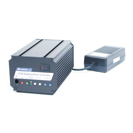
Front Power Switch (Press right side is On) www.velmex.com VXM Stepping Motor Controller On-Line Jog 1 Jog 2 Stop Run Local Moves Motor 2 Bus connection to second VXM for 3 and 4 motor operation Moves Motor 2 Moves Motor 1... -
Page 6: Auxiliary I/O
Jog Motor 2 CCW (Same as front panel button) (active low) Jog Motor 2 CW (Same as front panel button) (active low) Output 1 (normally low) Output 2 (normally low) Motor Wiring (for Velmex installed step motors) Step Motor Pin Motor Cable Slo-Syn Vexta... -
Page 7: Setup
Power cables. CAUTION: Motor cable length or connectors should not be altered without consulting Velmex first. Improper wiring can result in poor performance and damage to the VXM. Altered cables and resultant damage is not covered by the warranty. -
Page 8: Communication Methods
Programming of the VXM is accomplished by sending commands (ASCII characters) to the VXM through the RS-232 interface. The simplest method to send commands is with the Velmex COSMOS program, or with HyperTerminal in Microsoft Windows. NOTE: All command characters are case sensitive Another method to send commands is with commercially available languages such as VisualBASIC, C, LabVIEW, etc. - Page 9 F“ ” command VisualBASIC, C, LabVIEW, etc. R“ ” www.velmex.com VXM Stepping Motor Controller On-line -- Jog 1 -- -- Jog 2 -- wait for “^” Stop Local C“ ” Index Motor 1 Example Enable On-Line mode with echo on Incremental Index Motor #1 +400 steps (1rev.)
-
Page 10: Linking Vxms For 3 & 4 Motors
VXM controls that are configured as Master and Slave. Considerations when linking VXM controls together: Use only a Velmex approved cable for the bus connection, telephone handset cables will not work. Telephone cables reverse the 1 and 4 connection, a straight through cable is required. -
Page 11: Units & Directions
Direction is relative to the device the motor is used on. On screw drive actuators like UniSlides and BiSlides, positive is the direction moving away from the motor. On worm gear type rotary tables like the Velmex B4800 or B5990, positive is counter clockwise (CCW.) To reorient directions refer to the “setDM” command in Appendix... - Page 12 Command Summary (Common Commands) The following are the most common commands, refer to page 14 for an additional listing of commands for advanced users. Motor commands: Set steps to incremental Index motor CW (positive), m= motor# (1,2,3,4), x=1 to 16,777,215 ImM-x Set steps to incremental Index motor CCW (negative), m= motor# (1,2,3,4), x=1 to 16,777,215...
- Page 13 Operation commands: Quit On-Line mode (return to Local mode) Run currently selected program Null (zero) motors 1,2,3,4 absolute position registers Kill operation/program in progress and reset user outputs Clear all commands from currently selected program Decelerate to a stop (interrupts current index/ program in progress) Enable On-Line mode with echo "on"...
-
Page 14: Command Summary (Advanced Commands)
Command Summary (Advanced Commands) The following commands are for advanced VXM users. For more information on these commands refer to Appendices in this User’s Manual. Motor commands: SmM-x Read and assign analog input value to motor m speed (70% power), x=speed range (SAmM-x is 100% power) Program management commands: PMAx... - Page 15 Operation commands: Enable On-Line mode with echo off Grouping a <cr> with "^", ":", "W", "O" responses; Also Go after waiting or holding Put Controller on Hold (stop after each command and wait for go) Record motor positions for later recall with “x”,”y” commands Software reset controller Delete last command Status request commands:...
-
Page 16: Command Reference (Common Commands)
Command Reference (Common Commands) This section gives detailed explanations of the most common VXM commands. For the advanced user, refer to the Appendices for more information. Most commands with variables (except set commands) use the VXM's program memory space. The required memory needed per command is specified in this section. The VXM has 256 bytes of program memory for each program. - Page 17 position registers have a range of -8,388,608 to 8,388,607 steps, x should not be set to any number less than -8,388,608 or greater than 8,388,607. Memory usage = 4 bytes. Examples: This example sets motor 1 to index to absolute position 1200 : IA1M1200<cr>...
- Page 18 6000 steps/sec. in 1 step/sec. intervals. If this command is never used, the default speed will be 2000 steps/sec. NOTE: motor torque decreases as speed increases, and some motors have limited torque above 2000 steps/sec. If the motor torque is below the needed torque to move the load, the motor will stall (lose synchronism and proper position.) Memory usage = 3 bytes.
-
Page 19: Program Management Commands
Programming Shortcut: The motor designation in Acceleration, Speed, and Index commands is optional if the desired motor has already been set as the current motor. The current motor is motor 1 when the Controller is first turned on. The last motor jog/slewed will be the current motor number. -
Page 20: Looping/Branching Commands
Looping/Branching Commands Loop continually from the beginning or Loop-to-marker of the current program. The loop will occur to the last Loop-to-marker of the current program if it was set previously. This command can be used once in a program as the last command, it functions the same as a "continuous run input". - Page 21 oop A lways from beginning or Loop-to-marker of the current program x-1 times alternating direction of motor 1 indexes ( =2 to 65,535). A maximum of 10 nested loop commands can be used per run. Memory usage = 3 bytes. Examples: This example sets a loop to repeat 100-1 times all previous commands alternating motor 1 direction every repeat:...
-
Page 22: Commands
Pausing and Input/Output Commands Examples: This example pauses for 1 second: <cr> This example pauses for 15 seconds: <cr> This example pauses for 1 hour: <cr Example: <cr> This example pauses for 50 milliseconds (0.050 seconds): Example: <cr> This example pauses for 15 seconds holding output 1 high: user output 1 (I/O,14) will go to +5V for the duration of the pause. -
Page 23: Operation Commands
User output 1 "low". The user output 1 (I/O,14) will go to 0V. This is the state of the user output 1 on power-up. This command is used in conjunction with the "U5" command. Memory usage = 2 bytes. User output 1 high. The user output 1 (I/O,14) will go to +5V. This command is used in conjunction with the "U4"... -
Page 24: Status Request Commands
Enable On-Line mode with echo oFF. The single character "F" is used to put the VXM in the On-Line mode after power-up. No characters will be echoed back to the host. The VXM will still respond to motor position and status requests. Refer to the section "Communication Methods "... -
Page 25: Setup Commands
Send position of motor 3 to the host. When the VXM (Master) receives the single character "Z" it will transmit (from motor 1 in Slave) the value of the motor 3 Absolute Position Register. Below is what the host would receive if motor 3 is at negative 20. -
Page 26: Examples
Examples The following examples can be keyed into the VXM with a terminal program like HyperTerminal in Microsoft Windows, or the Velmex COSMOS software. Another method to send commands is with commercially available languages such as VisualBASIC, C, LabVIEW, etc. - Page 27 Function Incremental Example #4 Motors run RAM used Index Motor #2 600 steps Index start Function Example #5 Motors run RAM used Index Motor #1 both directions Auto-Reverse start Function Example #6 Motors run RAM used Repeating Index pausing 1 second Repeating Index between Indexes, return to start start...
- Page 28 Function Example #8 Motors run RAM used Raster Scan Raster scan with 1 sec. pauses and waiting for “G” at the end; then run backwards through raster scan = out = back start Function Example #9 Motors run RAM used Rectangle, with Output 1 and Rectangle Wait for Input 1 at each corner...
- Page 29 Function Example #10 Motors run RAM used Two Different Raster Scans Raster Scans using Loop-to-marker start This would do the entire pattern of the above example 5 times: Function Example #11 Motors run RAM used X,Y Matrix Moving Z Axis Up X,Y Matrix then Down at each Position start...
-
Page 30: Troubleshooting
Troubleshooting Symptom Possible Cause Power (Green LED) light does not come on Power supply not connected or AC cord not attached. Power switch not on. Circuit breaker tripped (white center protruding from breaker.) Motor makes noise but is not moving (Stalled) VXM not configured for Motor, speed too high, broken wiring, or jammed mechanism/motor. -
Page 31: Specifications
RS-232 Port Configuration: 8 Data, No Parity, 1 Stop, 9600 baud rate default Velmex COSMOS Software The COSMOS software for Windows is the easiest way to configure, program, and become familiar with the features of the VXM controller. COSMOS has the following... -
Page 32: Editing/Debugging Tools
Appendix A Editing/Debugging Tools *Revised: Command listing only on VXM firmware versions 1.21 & up Delete the last command in current program. This command should only be used for manual editing of programs with a terminal/ terminal program. Use the “C”... - Page 33 Get State of User Inputs, Motor 1 and Motor 2 Jog Inputs. Each input represents one bit of a binary value. The value the VXM sends is represented in the table below. Decimal Decimal Value Value 1=high Input Input Input Input No Inputs Activated...
-
Page 34: Appendix B Advanced Input/Output
Appendix B Advanced Input/Output Input commands: single character "W" to the host when this command is executed. The VXM will wait until a "G" is received from the host before proceeding in the program. Memory usage = 2 bytes. Wait for a Jog button to be pressed. This command allows user interaction, by initiating a jump to a specific program, or allowing the current program to proceed. - Page 35 Wait for the Jog 1- button to be pressed and debounced. Memory usage = 2 bytes. Wait for the Jog 1+ button to be pressed and debounced. Memory usage = 2 bytes. Wait for a low to high transition on the user input 1with debouncing for a mechanical push-button switch.
- Page 36 Output commands: User output 2 "low". The user output 2 (I/O,15) will go to 0V. This is the state of the user output 2 on power-up. This command is used in conjunction with the "U15" command. Memory usage = 2 bytes. User output 2 high.
- Page 37 Using the I/O on Slave (Bussed VXMs) Most of the inputs and outputs on a Slave VXM (in a Master/ Slave bussed configuration) are available through the Master. To access the user I/O on the second VXM (Slave) from the Master use the standard “Ux” commands +100. The Master will subtract 100 from the “Ux”...
-
Page 38: The Multifunction User Inputs
Appendix C The Multifunction User Inputs The program select feature of inputs 2 and 3 can setI et operating mode of User Inputs. The value for is a be used to select programs 0 to 3 for stand-alone number between 0 and 255 that can be derived from the applications. -
Page 39: Producing Trigger Outputs
Appendix D Producing Trigger Outputs There are three different methods to produce a pulse at an exact position: Index to a position, then while stopped use “PA”, “U1”, or “U5”/”U4” command. Use the Continuous indexing method with the “ “ command to produce a pulse out instead of stopping at the end of indexes. - Page 40 U7 Command Examples: This example makes an index on motor 1, producing a pulse at positions 1000,1100,1150,1250, and then runs motor 1 back to the start position: S1M1500,U7,I1M1000,I1M100,I1M50,I1M100,U9,IA1M0<cr> This example will Index motor 2 and pulse 100 times: U7,I2M400,LA100,U9<cr> This example makes an index on motor 2, producing a pulse with speed changes between each index: S2M1500,U7,I2M2000,S2M3000,I2M4000,S2M500,I2M800,U9,S2M3000,IA2M0<cr>...
- Page 41 Pulse Every “n” Steps The following command makes it possible to produce a repeating pulse for any number of motor steps from 1 to 32,767. Set “Pulse Every n # Steps” on output 2* for axis = 0 to 32,767 (0= disable/default.) Pulse width is settable with the command (default width is 10 msec.) “setPAx”...
- Page 42 getPmM Get value for “Pulse Every # Steps” for axi m= motor# (1,2,3,4) Value returned will between 0 and 32 setPAx (1=default.) Units are 10msec increments (10 x 10 seconds) NEW COMMAND: available only on VXM firmware versions 1.24 & up Example: This example will set the pulse width to 4 0 microseconds...
-
Page 43: Getting Motor Position When Moving
Appendix E Getting Motor Position When Moving It is possible to read motor position directly while motor is in motion using the commands. At high motor speeds it might not be timely or accurate enough to transfer motor position over the serial port while the motor is in motion. Another approach is to use an external trigger to tell the VXM to capture motor position(s) for later retrieval (after motion has ended.) The Automatic Deceleration Capture... - Page 44 Request captured motor 1 positions from FIFO buffer (all 4 positions.) NOTE: buffer data is automatically zeroed at the start of every run. Example: This example shows the values the VXM returned when the “!” was sent at positions 521,919, and 1149 while motor 1 was indexing. +0000521 +0000919 +0001149...
-
Page 45: Appendix F More Feedback/ Precision
Use Limit Switch for Home The limit switch on a typical Velmex slide assembly can provide a repeatability of better than 0.0004” (0.010 mm.) Using a limit switch on initial power-up to set a home is a good way to insure consistent performance from a precision positioning system. - Page 46 Indicate Limit Switch Encounter to Detect Faults A properly connected/ configured limit switch will always stop a motor immediately. Normally the host computer would not know if a limit switch stopped a move. With the “O” command described below, the VXM can be set to notify the host computer that it has hit a limit switch and stop the entire program too.
-
Page 47: Complex Profiles & Coordinated Motion
Appendix G Complex Profiles & Coordinated Motion Complex Profiles The VXM automatically does a simple profile move every time it is required to perform an index. This profile consists of a acceleration segment, slew segment, and a deceleration segment. Using the VXM’s Continuous indexing feature more complex motion profiles are possible. - Page 48 NOTE: A motor 3 or motor 4 index command must be before a motor 1 or motor 2 index for simultaneous operation to occur. Example: (I1M400,I3M800,)R This will not run the motors same time! Master/Slave Associated Programs* Two VXM controllers that are bussed together can be set to execute entire programs simultaneously.
-
Page 49: Appendix H Advanced Jog Mode
Appendix H Advanced Jog Mode When the On-Line (yellow) light is not lit, the VXM is in the Local/Jog mode. Using the front panel jog buttons, each motor can be jogged a single step or slewed to a default speed of 2000 sps (5 revs/sec.) in either direction. When a Jog button is pressed the motor moves 1 step (1/400 rev.) If the button is held for >0.3 second the motor will accelerate to a default speed of 2000 sps. - Page 50 Optional Digital Joystick The optional digital joystick allows remote jog control of a one or two axis VXM controller. The joystick provides four momentary outputs that are connected to the Jog Motor inputs on the Auxiliary I/O (internally connected to same inputs as the front panel jog buttons.) See previous page for information on jog function and speed settings.
- Page 51 Enabling Jog When a Program is Running Enable Jog while waiting for an input. This command will allow motor jogging, with the jog button/inputs, during the following wait commands: U0,U1,U30,U31,U50,U51, or U90. Memory usage = 2 bytes. Disable Jog while waiting for an input (default setting on power-up.) This command will disable motor jogging during a wait command.
-
Page 52: Appendix I The Analog Input
Appendix I The Analog Input The VXM has a 10-bit analog to digital converter for general use, motor speed setting, or for use with the optional Analog Joystick (see Appendix J.) The analog reference voltage is the internal +5VDC which is also used for the VXM’s internal logic. - Page 53 NOTE: When a “SmM-x” is stored in a program, the original x value will be kept with the command. However, when the “ ” command is used to list the program, the x value displayed will be the steps/sec speed converted from reading Ain. This feature allows viewing the actual derived speed the VXM is going to use.
-
Page 54: The Analog Joystick Option
Appendix J The Analog Joystick Option The VXM Proportional Speed Joystick provides a precise efficient one, two, three, or four axis variable speed positioning system when used with one or two VXM Stepping Motor Controllers. The Joystick is a compact long life 1 million cycle design packaged in a hand held size enclosure. - Page 55 setDA Set Joystick Deadband value. 20 to 100 (default=40) NOTE: Setting x to a low value makes it difficult to move just one axis without inducing motion on the opposite axis. Setting to a high value produces a noticeable delay when changing direction. getDA Get Joystick Deadband value.
- Page 56 Analog Joystick with One VXM The optional analog joystick can be used with a single VXM control. The joystick provides analog outputs for two VXM controls. With a single VXM one output is not connected resulting in “no function” in the one direction of the joystick. The analog joystick has a button switch connected to Input 2 for toggling between the primary and secondary settable jog speeds.
- Page 57 Analog Joystick with Two VXMs The joystick provides analog outputs for two VXM controls. A connection to each VXM is accomplished with a special Velmex “Y” cable. The analog joystick has a button switch connected to Input 2 for toggling between the primary and secondary settable jog speeds.
-
Page 58: I/O Electrical Specifications
Appendix K I/O Electrical Specifications All User I/O inputs and outputs (except limit switch inputs) are TTL levels (0 to +5VDC.) Inputs have a 2200 ohm resistor to +5VDC, and are activated by connecting to 0V. NOTE: When Input 4 (Stop) is held low (0V) program will not run.* Outputs are normally low, and can sink and source 20 mA max. - Page 59 Optional Auxiliary I/O Breakout Module The optional auxiliary I/O breakout module is a convenient method to interface to the VXMs auxiliary I/O. Wire connections can be made to all 15 I/O connections using the screw type terminal blocks. Specifications Wire size: 26 to18 AWG Boot material: Boot dielectric strength: 700 V/mil...
- Page 60 Appendix L Motor Torque Curves (Torque measured at 100% power settings) Vexta PK245 1.2A rev/sec 1.25 12.5 500 1000 2000 3000 4000 5000 6000 Speed steps/sec Vexta PK266-03 rev/sec 1.25 12.5 500 1000 2000 3000 4000 5000 6000 Speed steps/sec Slo-Syn M091 4.7A rev/sec 1.25...
- Page 61 Motor Torque Curves (Torque measured at 100% power settings) Vexta PK264-03 rev/sec 1.25 12.5 500 1000 2000 3000 4000 5000 6000 Speed steps/sec Vexta PK268-03 rev/sec 1.25 12.5 500 1000 2000 3000 4000 5000 6000 Speed steps/sec Slo-Syn M092 4.6A rev/sec 1.25 12.5...
-
Page 62: Appendix L Motor Torque Curves
Motor Torque Curves (continued) (Torque measured at 100% power settings) Slo-Syn M061 3.8A rev/sec 1.25 12.5 500 1000 2000 3000 4000 5000 6000 Speed steps/sec Slo-Syn M063 4.6A rev/sec 1.25 12.5 500 1000 2000 3000 4000 5000 6000 Speed steps/sec... - Page 63 Motor Torque Curves (continued) (Torque measured at 100% power settings) Slo-Syn M062 4.7A rev/sec 1.25 12.5 500 1000 2000 3000 4000 5000 6000 Speed steps/sec...
-
Page 64: Appendix M Advanced Motor Setup
Appendix M Advanced Motor Setup The VXM applies energy to the motors based on the size of the motor. The physical size is the important aspect that determines the amount energy the VXM will apply. The size of the motor is proportional to the motor’s current times it’s inductance. Motors of the same current are not the same to the VXM. - Page 65 Setting for other Motors The VXM can be used with motors not listed in the table on the previous page. Motors that are compatible with the VXM must meet the following criteria: 6 or 8 wire permanent magnet step motor Motor rated at a unipolar per phase current of 0.4 to 4.7 Amps If the motor you want to use does not meet the above requirements, STOP!The motor is not compatible with the VXM.
-
Page 66: Limit Switches And Home Switches
Appendix N Limit Switches and Home Switches The VXM by default recognizes normally closed (N/C to run) limit switches. The default mode is auto-detect normally closed switches. If the VXM is used with normally open or with a home switch, the limit switch mode will need to be changed. The following command sets the operating mode of the limit switch inputs. - Page 67 Procedure to configure the VXM for use with a home switch: (For rotary tables only, see page 27 & 46 for linear actuator homing example) 1. Determine which axis (axes) will be connected to a home switch and connect motor, limit cables, and set VXM for motor type/model attached.
- Page 68 Appendix O Controller Mode The VXM has a main mode register that can be set with the “setDMx” command. setDMx et operating mode of VXM. The value for is a number between 0 and 255 that can be derived from the table below. Example: This example would invert the direction of motor 1 from the standard.
- Page 69 setD0 The VXM can be set back to factory defaults with the “ ” command. This command will erase all programs, modes, and motor settings. setD0 Set VXM back to factory defaults CAUTION: All programs, settings, motor selections will be erased NOTE: The VXM will send “ËN”...
-
Page 70: Vxm Comparison To Nf90/ Vp9000
Appendix P VXM Comparison to NF90/ VP9000 Motor commands: Set steps to incremental Index motor CW (positive), m= motor# (1,2,3,4), x=1 to 16,777,215 ImM-x Set steps to incremental Index motor CCW (negative), m= motor# (1,2,3,4), x=1 to 16,777,215 AmMx Set Absolute Index distance, m=motor# (1,2,3,4), x= ±1 to ±16,777,215 steps IAmM0 Index motor to Absolute zero position, m=motor# (1,2,3,4) IAmM-0... - Page 71 Pausing and input output commands: Pause x tenths of a second, (x=0 to 65,5350) tenths of a millisecond when x is negative Pause x tenths of a second (x=0 to 65,535, 10 μsec pause when x=0) Altering output 1 high for duration of the pause, tenths of a millisecond when x is negative Wait for a "...
- Page 72 Operation commands: Quit On-Line mode (return to Local mode) Run currently selected program Null (zero) motors 1,2,3,4 absolute position registers Kill operation/program in progress and reset user outputs Clear all commands from currently selected program Decelerate to a stop (interrupts current index/ program in progress) Enable On-Line mode with echo "on"...
- Page 73 Commands for two controls connected by VXM bus: (i3,i1... Combine Index commands to run simultaneously on two VXM controllers connected by VXM bus Send data to Slave through Master Jog mode commands [i1,i2...] Read motor position (Digitize) Special function and setup commands: Backlash compensation, on when x=1, off when x=0 Indicate limit switch Over-travel to host, off when x=0, VXM sends "O"...
- Page 74 Feature Addressable Axes/ Control 1,2,3*,4* * By 2nd VXM linked with VXM bus Motor Compatibility Size 17 to size 34 (0.4 to 4.7 amp) Motor output torque as percent of NF90 185% @ 0.2 rev/sec (M091 Motor) 200% @ 5 rev/sec 340% @ 10 rev/sec Steps/ revolution Speed Range (steps/sec)
-
Page 75: Appendix Q Outline Dimensions
Appendix Q Outline Dimensions... - Page 76 Power Supply...
-
Page 77: Appendix R Model Configurations
Appendix R Model Configurations 1 Motor 2 Motor 3 Motor 4 Motor For OEM applications contact Velmex Sales/ Engineering department to find out more about how we can accommodate your special requirements. Possible Options: Half “U” enclosure Din rail mountable version... - Page 78 Rack Panel 1 Motor Rack Panel 2 Motor Rack Panel 3 Motor Rack Panel 4 Motor...
- Page 79 Appendix S Pick and Place Using JM-x* There are applications that require moving objects from a common pick location to an array of placement locations (or vice of versa.) One way to accomplish this would be to write individual moves to every array position followed by a move to the absolute pick position.
- Page 80 Function Example #12 Motors run Pick from common point and place Pick and Place in row start/end (Pick) 1000 8200 Position...
- Page 81 Pick and Place Using JM-x (continued) Function Example #13 Motors run Pick from common point and place Pick and Place in 3 rows 1600 7200 Position start/end (Pick) 1200 2400...
- Page 82 Function Example #14 Motors run Pick from common point and place Pick and Place in rows, Y axis moves tray of parts to next row U5,P1 start/end (Pick) 1st Row Tray ) ) ) ) ) start/end (Pick) 2nd Row...
- Page 83 Pick and Place Using JM-x (continued) The following example is the similar to example 14 except for a third axis (Z) moves part up from pick location and down at place location, there are 3 rows instead of 2, The program will start again with the Run button.
- Page 84 Function Example #16 Motors run Pick from rows and place at common location, Pick and Place Y axis moves tray of parts to next row (Place) 1st Row start/end Tray ) ) ) ) ) (Place) 2nd Row...
- Page 85 Appendix T Stand-alone Methods to Select/Alter Program Sometimes it is necessary for the user to interact directly with the VXM to select a program, stop program, change speed, or change to different routine based on an external input. Below are the four categories and the methods for user interaction with the VXM in standalone applications.
- Page 86 Skip Next Command If Input High*/Low** Skip next command if Input 1 (I/O,5) is high. 2 bytes Memory usage = Skip next command if Input 1 (I/O,5) is low. Memory usage = 2 bytes. Skip next command if Input 2 (I/O,6) is high. Memory usage = 2 bytes.
- Page 87 Stepping Motor Controllers manufactured by Velmex are warranted to be free from defects for a period of two (2) years on all parts. Velmex's obligation under this warranty does not apply to defects due, directly or indirectly, to misuse, abuse, negligence, accidents, or unauthorized repairs, alterations, or cables/connectors that require replacement due to wear.
- Page 88 7550 State Route 5 & 2 0 Bloomfield, NY 14469 Copyright 2002 Velmex Inc. All rights reserved. Velmex, the Velmex logo, UniSlide, and BiSlide are trademarks of Velmex Inc. All other trademarks are the property of their respective owners. 12-29-04...
Need help?
Do you have a question about the VXM-3 and is the answer not in the manual?
Questions and answers