Sign In
Upload
Manuals
Brands
VELMEX Manuals
Controller
VXC-1
VELMEX VXC-1 Manuals
Manuals and User Guides for VELMEX VXC-1. We have
1
VELMEX VXC-1 manual available for free PDF download: User Manual
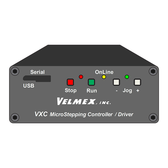
VELMEX VXC-1 User Manual (144 pages)
MICROSTEPPING MOTOR CONTROLLER / DRIVER
Brand:
VELMEX
| Category:
Controller
| Size: 5 MB
Table of Contents
Table of Contents
2
Precautions
13
High Integration Stepping Motor Controller/Drive
15
Model Numbers
15
Function
16
External Features
17
Setup
18
Configuring VXC with Device ID
19
Device ID for Limit, Home/Stall Settings
20
Jog Mode
20
Optional Joysticks
20
Serial Communication
21
Units & Direction
22
Units for Velmex Positioners
23
Unit Conversion
23
Other Formulas
23
Motion Commands
24
The Difference between Incremental and Absolute Indexes
24
Incremental: I1M1000
24
Absolute: IA1M2000
24
Sending Commands to the VXC
24
Incremental Index (Move an Increment)
25
Absolute Index (Move to Position)
26
Index to Absolute Zero (Move to Zero)
27
Zero Motor Position
27
Move to Positive to Home/Limit
28
Move to Negative to Home/Limit
28
Speed
29
How to Determine Maximum Speed
30
Smart Speeds
30
Acceleration
31
How to Determine Maximum Acceleration
31
Smart Acceleration
31
Program Coding Shortcut
32
Interactive Mode
33
Interactive Examples
34
Standalone Mode
35
Standalone Examples
36
Command Summary (Common & Advanced)
37
Operation Commands
37
Editing/Debugging Tools
37
Setup Commands
37
Status Request Commands
38
Motion Commands
38
Program Management Commands
39
Looping & Branching Commands
39
Pausing, Input/Output Commands
39
Program Management Commands
41
Editing/Debugging Tools
43
Program Examples
44
Example 1 Enable On-Line Mode Echo on
44
St Motor 400 Steps
44
Example 2 Single Axis Incremental Index Move 1
44
Example 3 Single Axis Incremental Index Move 1
44
Example 4 Clear All Commands from Current Program & Zero Motor Position
44
Example 5 Clear Previous & Index Move 2Nd Motor 600 Steps
45
Example 6 Index Motor 1 both Directions (Auto Reverse)
45
Example 7 One-Axis Index Pausing 0.5 Sec, Loop, Return to Start
45
Example 8 One-Axis Index Using Index Absolute Zero to Return to Start
45
Example 9 Two-Axis Out/Down, Wait for Run Button, Rapid Return to Start
45
Example 10 Two-Axis Raster Scan with 0.1 Pulse at each Stop & Return to Start
46
Example 11 Two-Axis with Two Different Raster Scans & Return to Start
46
Example 12 Three-Axis XY Matrix, Z Up/Dn at each Position, & Return to Start
47
Example 13 Two-Axis Rectangle, Wait Input 1 at each Corner, Loop Forever
47
Example 14 One-Axis Index/10Ms Pulse, Looping, Using Smart Acel & Speed
47
Looping/Branching Commands
48
Loop
48
Jump
49
Pause
50
Ux Commands
50
Wait for Input
50
Input 1
50
Run Low/High
52
Conditional Branch on Input
52
Wait for Front Panel Button
52
Output
53
Output 1
53
Output 2
53
Output 3
53
Output 4
53
Outputs on Axes 2,3,4
54
Axis 2 Outputs
54
Axis 3 Outputs
54
Axis 4 Outputs
54
Jog While Waiting
55
Programmable Serial Prompt
55
Continuous Indexing
55
Operation Commands
57
Online/Off-Line
57
Clear Previous
57
Run/Start
57
Interrupt Motion
57
Status Request Commands
58
Help Menu
58
Help Menu in Jog Mode
58
Help Menu in Online Mode
58
Motor Position
58
Verify Status
59
Capture Position
59
Retrieve Captured Positions
59
Position When Decelerated
60
Read Analog Value
60
List All Settings
61
Backlash Compensation
62
Motor Type
62
Limit Mode
62
Firmware Status Request
62
Jog/Joystick Settings
62
Digital Jog
62
Analog Joystick
62
Pulse Output Settings
63
User Input Mode
63
Motor Jog Function
63
Troubleshooting
64
Technical Specifications
66
Environmental Requirements
66
Model VXC-1
66
Function
66
Physical
66
Cabling
66
Electrical Requirements
66
I/O
66
Serial Ports
66
Model VXC-2
67
Function
67
Physical
67
Cabling, Electrical Requirements, I/O, Serial Ports
67
Model VXC-3
67
Model VXC-4
67
Power Supply
68
Function
68
Physical
68
Electrical Requirements
68
Warranty
68
Appendix A (Motor Settings)
69
Setting Motor Type
69
Non-Standard Motors
70
Appendix B (Limits/Home/Stall Detect)
71
Limit Switch Inputs
71
Home/Stall Detect Input
72
Limits, Home, Stall Detect Function Interaction
73
Device Compatibility with Limits, Home, Stall Detect
73
Using a Limit for Home Reference
74
Programming Sequence for Homing to a Limit Switch
74
Example 15 Move Negative into Limit Switch, then Back 400 Steps, & Zero Position
74
Reasons to Use a Dedicated Home Switch
74
Using a Home Switch on Home Input
75
Homing to a Home Switch on Rotary Tables Without Limit Switches, and When Home Switch Is at Limit End on Devices with Limit Switches
75
Example 16 Move Negative into Home Switch and Zero Position Example
75
Example 17 Move Positive into Home Switch and Zero Position 1000 Steps Away
76
Programming Sequence for Homing to a Centrally Located Home Switch with Limit Switches
76
Example 18 Move Negative into Limit Switch, then + to Home Switch, and Zero Position
76
Appendix C (Referencing/Feedback)
77
More Feedback & Precision
77
Limit or Home Switch for Initial Reference
77
Backlash Compensation to Improve Accuracy
77
Example 19 Typical Homing Routine (Speed 500, Move to +Limit, Move Back 200, Zero Position)
77
Backlash Compensation Set Examples
78
Indicate Limit Switch Encounter
78
Stall Detect Option to Verify Movement
78
Appendix D (Digital Jog)
79
Advanced Digital Jog Mode
79
Optional Digital Joystick
80
Jog Function Settings
81
Custom Jog Distances
82
Appendix E (Analog/Jog)
83
Analog Input
83
Analog Joystick Option
84
Analog Joystick (2 Axis Finger Stick)
86
VC Series Analog Joystick (2 & 3 Axis)
87
Appendix F (Faults)
88
Fault Checking
88
Immediate Checks
88
Level 1 Faults
89
Level 2 Faults
89
Level 3 Faults
90
Level 3 Faults by Common Flash Code
91
Level 3 Faults Checked at Power-Up Only
92
Index of All Faults
92
Appendix G (Serial Ports)
93
Serial Port Connections
93
USB Port
93
How to Find COM Port VXC Is on in Microsoft Windows
93
How to Test USB Cable for a Reliable Connection
94
RS-422 Port
94
RS-422 Adapters
95
Appendix H (Modes)
96
Controller Mode
96
Appendix I (Inputs)
98
Multifunction User Inputs
98
Appendix J (Dynamically Read Position)
100
Getting Motor Position When Moving
100
The Automatic Deceleration Capture
100
The Triggered Position Capture
100
Retrieve Captured Positions
100
Appendix K (Output Triggers)
101
Producing Trigger Outputs
101
Index, Stop, Output
101
Example 20 Index Motor One 400 Steps, Pause/Output
101
Continuous Indexing
101
U7 Continuous Indexing Command Examples
102
Pulse Every "N" Steps
103
Appendix L (Complex Motion)
105
Complex Profiles/Coordinated Motion
105
Complex Profiles
105
Coordinated Motion
105
Master/Slave Associated Programs
106
Appendix M (Math)
107
Math Capability
107
Math Expressions
108
If" Conditional Statement
109
If" Expressions
109
End" Statement
109
Setting & Proportioning Speed to Analog Input
110
Example 21 Setting Speed Proportional to Analog Input
110
Producing Custom Accelerations / Decelerations
111
Calculating Position in Pick & Place Applications
111
Example 22 Extra Long Accelerations
111
Example 23 Calculated Pick and Place
111
Self-Determining Center of System Travel
112
Self-Calculating Ratios of Absolute Position
112
Example 24 Calculating Center of Travel
112
Example 25 Self-Calculating Ratios of Distance
112
Appendix N (Input Select Programs/Speed)
113
Stand-Alone Methods to Select Program
113
External Selection of Programs
113
External Setting of Speed
113
Program Interruption
113
Conditional Branching
113
Skip Next Command if Input High/Low
114
Example 26 Change Speed Using U11 & U21
114
Example 27 Change Program Using U12
114
Appendix O (Setting Baud Rate)
115
Baud Rate Setting Methods
115
Setting Baud with Setbx Command
115
Setting Baud at Front Panel
115
Appendix P (VXC Versus VXM)
116
VXC Compatibility with VXM
116
VXC New Features Compared to Previous VXM
116
VXC Versus VXM Settings Differences
117
VXC Versus VXM Command Differences
117
VXC New Commands
118
VXC New Set/Gets
118
VXC Different Values
118
Appendix Q (Microstepping)
119
Dynamic & Static Microstepping
119
Appendix R (Dimensions)
120
VXC Dimensions
120
VXC Models
120
Rack Mounting
121
Cleat Mounting
122
Power Supply Dimensions
123
Appendix S (I/O Specifications)
124
I/O Electrical Specifications
124
Optional Auxiliary I/O Breakout Module
125
Appendix T (Motor Torque)
126
Motor Torque Curves
126
VML111-1.2-S (28CM006) Motor
126
Torque Graph 1 for VML111-1.2-S (28CM006) Motor @ 24V
126
VML112-1.2-S (28CM010) Motor
127
Torque Graph 2 for VML112-1.2-S (28CM010) Motor @ 24V
127
VML113-1.2-S (28CM013) Motor
128
Torque Graph 3 for VML113-1.2-S (28CM013) Motor @ 24V
128
VML171-1.5-S (42CM02) Motor
129
Torque Graph 4 for VML171-1.5-S (42CM02) Motor @ 24V
129
VML173-2.5-D (42CM06-SZ) Motor
130
Torque Graph 5 for VML173-2.5-D (42CM06-SZ) Motor @ 24V with Damper
130
Torque Graph 6 for VML173-2.5-D (42CM06-SZ) Motor @ 24V
130
Torque Graph 7 for VML173-2.5-D (42CM06-SZ) Motor @ 28V, 100% Power, With/Without Damper
131
VML231-3.0-D (57CM06) Motor
132
Torque Graph 8 for VML231-3.0-D (57CM06) Motor @ 24V with Damper
132
Torque Graph 9 for VML231-3.0-D (57CM06) Motor @ 24V
132
Torque Graph 10 for VML231-3.0-D (57CM06) Motor @ 28V, 100% Power, With/Without Damper
133
VML232-4.0-D (57CM13) Motor
134
Torque Graph 11 for VML232-4.0-D (57CM13) Motor @ 24V with Damper
134
Torque Graph 12 for VML232-4.0-D (57CM13) Motor @ 24V
134
Torque Graph 13 for VML232-4.0-D (57CM13) Motor @ 28V, 100% Power, With/Without Damper
135
VML233-5.0-D (57CM22C) Motor
136
Torque Graph 14 for VML233-5.0-D (57CM22C) Motor @ 24V with Damper
136
Torque Graph 15 for VML233-5.0-D (57CM22C) Motor @ 24V
136
Torque Graph 16 for VML233-5.0-D (57CM22C) Motor @ 28V, 100% Power, With/Without Damper
137
VML341-4.0-D (86M35) Motor
138
Torque Graph 17 for VML341-4.0-D (86M35) Motor @ 24V with Damper
138
Torque Graph 18 for VML341-4.0-D (86CM35) Motor @ 24V
138
Torque Graph 19 for VML341-4.0-D (86CM35) Motor @ 28V, 100% Power, With/Without Damper
139
VMN231-4.2-D (ST5918X3008) Motor
140
Torque Graph 20 for VMN231-4.2-D (ST5918X3008) Motor @ 24V with Damper
140
Torque Graph 21 for VMN231-4.2-D (ST5918X3008) Motor @ 24V
140
Torque Graph 22 for VMN231-4.2-D (ST5918X3008) Motor @ 28V, 100% Power, With/Without Damper
141
Vmn232-4.2-D (St5918S3008-B)
142
Torque Graph 23 for VMN232-4.2-D (ST5918S3008-B) Motor @ 24V with Damper
142
Torque Graph 24 for VMN232-4.2-D (ST5918S3008-B) Motor @ 24V
142
Torque Graph 25 for VMN232-4.2-D (ST5918S3008-B) Motor @ 28V, 100% Power, With/Without Damper
143
Cable Length Versus Torque
144
Example VM341-4.0-D-F, 2500 Steps/Sec, 100% Power (S+2500), "TF with CLC" & 50 Ft Cable
144
Advertisement
Advertisement
Related Products
VELMEX VXM-3
VELMEX VXM-1
VELMEX VXM-2
VELMEX VXM-4
VELMEX VXC-2
VELMEX VXC-3
VELMEX VXC-4
VELMEX Categories
Controller
More VELMEX Manuals
Login
Sign In
OR
Sign in with Facebook
Sign in with Google
Upload manual
Upload from disk
Upload from URL