
Subscribe to Our Youtube Channel
Related Manuals for Noraxon 508

Summary of Contents for Noraxon 508
- Page 1 DTS 2D Electrical Goniometer User Manual Model 508 DTS 2D Electrical Goniometer User Manual P-5088 Rev J...
-
Page 2: Authorized European Representative
Noraxon and myoRESEARCH are registered trademarks and the Noraxon logo, myoANALOG, myoFORCE, myoMETRICS, myoMOTION, myoMUSCLE, myoPRESSURE, myoVIDEO, myoSYNC, NiNOX, TRUsync and Ultium are common-law trademarks of Noraxon U.S.A., Inc. All other trademarks are the property of their respective owners. ©2018, all rights reserved. -
Page 3: Table Of Contents
DTS 2D Electrical Goniometer User Manual Table of Contents Section 1: Introduction Brief Description ...................... 1 Intended Use ......................1 Contraindications ...................... 1 Section 2: Definitions Graphic Symbols and Meanings ................2 Glossary of Terms ....................2 Section 3: Identification Model Designation .................... - Page 4 DTS 2D Electrical Goniometer User Manual Section 14: List of Spare Parts and Consumables Replaceable Items ....................22 Section 15: Taking Product Out of Operation Disposal of Equipment and Batteries ............... 22 Section 16: Specifications of the Product Expected Useful Lifetime..................
-
Page 5: Section 1: Introduction
It also allows for placement of the sensor on uneven surfaces. Due to the amplifier built into the cable, it has direct plug-in functionality to Noraxon devices. Intended Use Noraxon’s DTS 2D Electrical Goniometer is used to measure angular displacement. This particular model can measure in one or 2 dimensions. Intended Users Researchers and individuals trained in physical medicine, physical therapy or ergonomics Subject Populations –... -
Page 6: Section 2: Definitions
Glossary of Terms Channel – In the case of the Electrical Goniometer a channel represents any one of the sixteen measurable signals designated as Channel 1 through Channel 16 in the Noraxon systems. DTS – Abbreviation for Direct Transmission Frequency Electrical Goniometer –... - Page 7 DTS 2D Electrical Goniometer User Manual Multi-Channel Sensor – Certain Sensor Types provide more than one signal. Thus a Multi-Channel Sensor behaves like two or three standard Sensors. An example is a 3-D Accelerometer that provides acceleration data for the x, y and z directions. RF –...
-
Page 8: Section 3: Identification
Model 508 2D Electrical Goniometer Product Versions and Configurations The model 508 DTS 2D Electrical Goniometer can work in conjunction with any of the Noraxon Wired EMG systems. As the Electrical Goniometer requires software to perform its function, the equipment is offered in combination with the following computer program packages. -
Page 9: Section 4: General Warnings And Cautions
DTS 2D Electrical Goniometer User Manual Section 4: General Warnings and Cautions Risks and Benefits There is no identified risk of physical harm or injury with use of the Electrical Goniometer sensor. The benefit provided by use of the device is the provision of objective measures to assess the severity of pathological human movement conditions and gauge any subsequent improvement offered by therapy, training, prosthetic alterations or ergonomic design changes. -
Page 10: Section 5: Getting Started
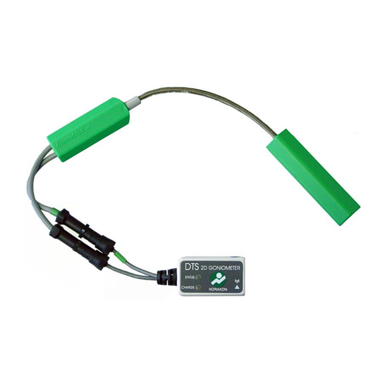
Please see the appropriate hardware manual for the appropriate EMG system. Section 6: Preparing the Product for Use (Set-up Instructions) Unpacking and Component Identification Two Inline 1D/2D Electrical Goniometer (part #508) Note: The 1D Goniometer has only one cable X-Y Goniometer Sensor (Part# PGXY) Note: The Goniometer Sensor cable... -
Page 11: Component Interconnections
5. Please include the following: Your name, Company/Organization Name, Serial Number on TeleMyo 2400T G2 and the Activation Key. 6. Noraxon Support will email or respond by phone with the Activation Code 7. Enter the provided Activation Code to remove any restrictions on use. -
Page 12: Companion Software Configuration
MR3 software. Companion Software Configuration Before the Electrical Goniometer can be used with the Noraxon EMG system can be used, the companion software must be configured to recognize the different components that make up the system. - Page 13 DTS 2D Electrical Goniometer User Manual MyoResearch XP Configuration Step 1 Enter the Hardware Setup screen and setup the Noraxon EMG system in accordance with its provided hardware manual. Step 2 Select the appropriate EMG DTS system icon and hit Settings in the A/D Input bar to enter the Serial number.
- Page 14 DTS 2D Electrical Goniometer User Manual Step 4a Highlight the channel number that will use the Goniometer and click on the check box in the lower right corner of the 2D Goniometer icon Note: The 2D Goniometer will require 2 channels. Step 4b Click on the check box next to the channel the Electrical Goniometer...
- Page 15 DTS 2D Electrical Goniometer User Manual MR3 Configuration Step 1 Enter the Hardware Setup screen and setup the Noraxon EMG system in accordance with its provided hardware manual. Be sure to enter the Electrical Goniometer serial numbers into the correct channel.
- Page 16 DTS 2D Electrical Goniometer User Manual Step 5 Continue with the measurement setup as described in the EMG system’s hardware manual. P-5088 Rev J...
-
Page 17: Section 7: Pre-Use Check-Out
DTS 2D Electrical Goniometer User Manual Section 7: Pre-Use Check-Out Normal Appearance of Signals In the idle state, the STATUS indicator will flash green at a low rate. While acquiring signals the STATUS indicator will flash green at a low, once per second rate. When in the charging station, if the CHARGE indicator is glowing amber the sensor is charging. -
Page 18: Section 8: Operating Instructions
Normal Functions with Interface to a PC When used with the companion software the Noraxon’s DTS 2D Electrical Goniometer is used to measure angular displacement. This particular model can measure in 2 dimensions for any joint in the body, or along the spine to measure spinal movement. -
Page 19: Section 9: Accessories And Optional Modules
Accessories Part Image Description Elastic strap for adhering the sensor to the user As new accessories may be available after the time of printing, please check Noraxon’s website at this link for the latest offerings. http://noraxon.com/products Options Part No. Image Description More…... -
Page 20: Section 10: Cleaning
The Electrical Goniometer Sensor is not warranted against exposure to any of the conventional forms of sterilization(autoclave, heating, etc.). Users wishing to utilize this equipment in a sterile environment, such as an operating theater, should consult Noraxon for other options. P-5088 Rev J... -
Page 21: Section 11: Maintenance
DTS 2D Electrical Goniometer User Manual Section 11: Maintenance Safety Precautions When Performing Maintenance No precautions required. Maintenance by Users Because the DTS sensor batteries are Li-Ion, the only battery maintenance required is recharging. Charging the DTS Sensors The DTS Sensors may be charged using the DTS Sensor Charging Station •... -
Page 22: Maintenance By Qualified Individuals
Companion Software Updates • Perform a backup of the data folders to a separate drive as a precaution. • Click on the Patch/Update link provided in the email or as given on the Noraxon website http://noraxon.com/software-downloads • Download the Patch/Update file. -
Page 23: Section 12: Trouble Shooting, Fault Diagnosis
(esp. at long distances) of-sight relationship between sensor and receiver Website Link to FAQ Answers to common questions can be found at Noraxon’s Frequently Asked Questions (FAQ) website page at this link: http://noraxon.com/faq Other educational material is available at this link: http://noraxon.com/educational-materials... -
Page 24: Radio Considerations
WiFi enabled devices. Despite all this competing radio activity the Noraxon systems are able to discern its particular information from all the surrounding radio traffic. Reliable transmission depends on good signal quality. -
Page 25: Section 13: Service And Repair
If you are shipping from outside the USA please use UPS, FedEx, DHL, or EMS (US Postal Service) and not a freight-forwarder. Using a freight-forwarder incurs additional brokerage fees. If a package is shipped to Noraxon via a carrier other than the ones listed above, it may be refused. -
Page 26: Section 14: Spare Parts And Consumables
DTS 2D Electrical Goniometer User Manual Section 14: Spare Parts and Consumables Replaceable Items Part Image Description Elastic strap for adhering the sensor to the user Section 15: Taking Product out of Operation Disposal of Equipment and Batteries The DTS 2D Electrical Goniometer Sensor contains a Li-Polymer battery, which may be hazardous if disposed of incorrectly. -
Page 27: Section 16: Specifications Of The Product
DTS 2D Electrical Goniometer User Manual Section 16: Specifications of the Product Expected Useful Lifetime The 2d Electrical Goniometer sensor has a usable life of seven years. The 2d Electrical Goniometer sensor operates with a rechargeable Lithium Ion battery. The battery capacity will decline with ongoing use and require replacement after 500+ discharge/charge cycles to preserve the device’s rated 8 hours of operating time. -
Page 28: Section 17: Technical Information
DTS 2D Electrical Goniometer User Manual Section 17: Technical Information Block Diagram Model 508 Electrical Goniometer Sensor Coming soon… Theory of Operation The working mechanism is the same for all three types of sensor (see next section: F35, SG, Q). -
Page 29: Technical Specifications
DTS 2D Electrical Goniometer User Manual Crosstalk Crosstalk is defined as the ability of the goniometer to measure independently the simultaneous angular movements of a joint in 2 degrees of freedom. Most of the joints discussed in this manual do not have crosstalk, with the exception being the wrist and hip. Provided the guidelines on the size selection and mounting position are followed, crosstalk between the 2 channels will be minimized to an acceptable level. -
Page 30: Section 18: Appendices
Use a network sniffer program to determine which WiFi RF channels are being used in your area. InSSIDer” is a network sniffer with a graphical display that is available as a free download from the Noraxon website at: http://www.noraxon.com/docs/default-source/Utility-Downloads/noraxon-inssider2- installer.zip?sfvrsn=0 This network sniffer is compatible with Windows XP, Vista and 7 (32 and 64-bit). -
Page 31: Appendix B-Sensor Rf Channel Frequencies
DTS 2D Electrical Goniometer User Manual Appendix B – Sensor RF Channel Frequencies The Respiration Sensor operates on a RF channel. The RF Channels (A-H) are assigned to the RF frequencies according to the table below. RF Channel Frequency (GHz) 2.400-2.409 2.415-2.424 2.427-2.436... -
Page 32: Appendix C-Radiation Exposure Information Regarding Use Of Dts Sensors
(next to the person’s head). At present, Noraxon identifies no restrictions on use and placement of the DTS sensors on any portion of the human body. The DTS sensors operate at radio frequencies known to effect older style pacemakers. -
Page 33: Appendix D-Radio Regulatory Statements
DTS 2D Electrical Goniometer User Manual Appendix D – Radio Regulatory Statements FCC Statement This device complies with part 15 of the FCC rules. Operation is subject to the following two conditions: (1) This device may not cause harmful interference, and (2) this device must accept any interference received, including interference that may cause undesired operation. -
Page 34: Appendix E-Available Goniometer Sensor Types
DTS 2D Electrical Goniometer User Manual Appendix E – Available Goniometer Sensor Types In general, there are no fixed rules governing which size of sensor is most suitable for a particular joint; this depends on the size of the subject. The sensor must be capable of reaching across the joint so that the two endblocks can be mounted where least movement occurs between the skin and underlying skeletal structure. -
Page 35: Appendix F-Electrical Goniometer Sensor Application
DTS 2D Electrical Goniometer User Manual Appendix F – Electrical Goniometer Sensor Application Fingers and Toes – Goniometer F35 The F35 goniometer is a single axis goniometer intended for use on fingers and toes. Angles are measured by rotating one endblock relative to the other about axis X-X. The goniometer is not designed to measure rotations about Y-Y. - Page 36 DTS 2D Electrical Goniometer User Manual Start with the subject’s shoulder in abduction at 90̊ and elbow flexed at 90̊ , such that the forearm is close to full pronation. As shown in Fig. 9, attach the distal endblock to the dorsal surface over the third metacarpal with the center axis of the hand and endblock coincident.
- Page 37 DTS 2D Electrical Goniometer User Manual Elbow 1) Position the subject’s shoulder in abduction at 90 degrees with the elbow and forearm in neutral position. 2) Attach the distal endblock to the forearm with the center axis of the endblock coincident with the center axis of the forearm.
- Page 38 DTS 2D Electrical Goniometer User Manual Knee 1) Have the subject stand in the neutral position with the foot on a flat surface. 2) Attach the distal endblock laterally on the leg so the axes of the leg and endblock coincide, when viewed in the sagittal plane (figure 15).
- Page 39 DTS 2D Electrical Goniometer User Manual Back 1) Attach the proximal endblock to the sacral area at S1 as shown in figure 17. 2) With the patient upright and the goniometer near minimum length, attach the sliding endblock to the back at T12-L1 (this will vary depending upon patient height). 3) Zero the goniometer with the patient in this upright position.
- Page 40 DTS 2D Electrical Goniometer User Manual Forearm Pronation/Supination Attach the two endblocks of the torsiometer to the forearm as shown in Fig. 19 with the slider mechanism approximately midway between the two extremes. Measurements of pronation/supination may now be made from the grey plug. Movements of wrist flexion/extension or radial ulnar deviation will not affect the output.
- Page 41 DTS 2D Electrical Goniometer User Manual Sign Conventions for Selected Joints (Lefts vs. Right) The sign convention for certain joints will differ depending which side of the body the sensor is attached to. Sign conventions for the most common joints are shown below and following pages. Finger, Wrist and Elbow P-5088 Rev J...
- Page 42 DTS 2D Electrical Goniometer User Manual Knee and Hip Ankle and Back P-5088 Rev J...
Need help?
Do you have a question about the 508 and is the answer not in the manual?
Questions and answers