Advertisement
Table of Contents
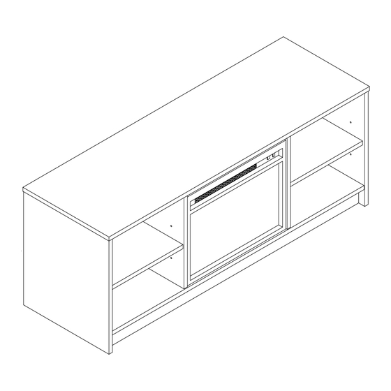
1524015WCOM
Fireplace/TV Stand
Date of Purchase ___ / ___ / ___
Lot Number:
THIS INSTRUCTION BOOKLET CONTAINS IMPORTANT SAFETY INFORMATION. PLEASE READ AND KEEP FOR FUTURE REFERENCE.
WARNING
Unit can tip over causing severe injury or death.
- Do Not allow children to climb on unit
- Put heavy items on lower shelves
- Two people required for assembly
Do Not Return This Product!
Contact our customer service team for help first.
Call: 1-800-489-3351 (toll free)
Visit: www.ameriwoodhome.com
Easy
Assembly Difficulty Meter
Follow Ameriwood Home
B341524015COM0E
Tough
You
Tube
Advertisement
Table of Contents

Subscribe to Our Youtube Channel
Related Manuals for Ameriwood HOME 1524015WCOM


Summary of Contents for Ameriwood HOME 1524015WCOM
- Page 1 Easy Tough Unit can tip over causing severe injury or death. Assembly Difficulty Meter - Do Not allow children to climb on unit Follow Ameriwood Home - Put heavy items on lower shelves - Two people required for assembly Tube...
-
Page 2: Helpful Hints
Contact Us! Do NOT return this product! Contact our friendly customer service team first for help. Call us! 1-800-489-3351 Monday-Friday Visit ameriwoodhome.com to view the limited warranty valid in the U.S. and Canada. Helpful Hints PEOPLE NEEDED FOR ASSEMBLY: 2 - Open your item in the area you plan to keep it to avoid excessive heavy lifting. -
Page 3: Before You Start
Before You Start Read through each step carefully and follow the proper order Separate and count all your parts and hardware Parts are labeled on the surface or edge of the part Give yourself enough room for the assembly process Have the following tools: #2 Phillips Head Screwdriver, a ruler or tape measure and Hammer Caution: If using a power drill or power screwdriver for screwing,... - Page 4 Before You Start Please Note: You may need to lightly tap the wood dowels with a hammer into the holes during your assembly process. Not Actual Size Wood Dowel Actual Size Wood dowel will extend out approximately 3/8". 2 PEOPLE NEEDED FOR ASSEMBLY CAUTION: Failure to use 2 people for assembly could result in unit damage or personal injury...
-
Page 5: Board Identification
Board Identification Not actual size Left Panel Right Panel Left Partition Right Partition 31524015010 31524015030 31524015020 31524015040 Bottom Back (x2) 31524015060 31524015050 31524015070 Kick Adjustable Shelf (x2) 31524015090 31524015080 ameriwoodhome.com... - Page 6 Board Identification Not actual size ameriwoodhome.com...
-
Page 7: Part List
ote: Your unit may contain extra hardware. Part List Actual Size (x4) (x20) (x12) (x5) (x20) #A21670 #A23030 #A22710 #A22760 #A22700 cam bolt wood dowel confirmat quickloc cam lock (x3) (x8) (x8) #A12120 #A80250 #A245015 7/16" screw shelf support decorative cam cover Not Actual Size 9b x3 (x1) - Page 8 STEP 1 (x2) (x4) (x1) Dowels extend out 3/8". For more details, please see page 4 Insert two cam locks (1), four cam bolts (2) and one wood dowel (3) into the Left Panel (A). Proper orientation of cam lock ameriwoodhome.com...
- Page 9 STEP 2 Dowels extend out 3/8". (x2) (x1) (x4) For more details, please see page 4 Insert two cam locks (1), four cam bolts (2) and one wood dowel (3) into the Right Panel (B). Proper orientation of cam lock ameriwoodhome.com...
- Page 10 STEP 3 (x1) (x2) (x2) Dowels extend out 3/8". For more details, please see page 4 Insert two cam locks (1), two cam bolts (2) and one wood dowel (3) into the Left Partition (C). Proper orientation of cam lock ameriwoodhome.com...
- Page 11 STEP 4 (x1) (x2) (x2) Dowels extend out 3/8". For more details, please see page 4 Insert two cam locks (1), two cam bolts (2) and one wood dowel (3) into the Right Partition (D). Proper orientation of cam lock ameriwoodhome.com...
- Page 12 STEP 5 Dowels extend out 3/8". (x8) (x4) For more details, please see page 4 Insert four cam locks (1) and two wood dowel (3) into each Back (E). Proper orientation of cam lock Proper orientation of cam lock unfinished surface ameriwoodhome.com...
- Page 13 STEP 6 (x8) Press in eight cam bolts (2) into the Top (F). ameriwoodhome.com...
- Page 14 STEP 7 (x4) (x4) Dowels extend out 3/8". For more details, please see page 4 Insert four cam locks (1) and 4 wood dowels (3) into Bottom (G). finished edge Proper orientation of cam lock unfinished surface Proper orientation of cam lock ameriwoodhome.com...
- Page 15 STEP 8 Pressed into hole and flush against board (x5) Insert five quicklocs (4) into Kick (I). Proper orientation of quickloc Proper orientation of quickloc Proper orientation of quickloc ameriwoodhome.com...
- Page 16 STEP 9 Turn clockwise to lock in place. Position Kick (I) onto Bottom (G) so three quicklocs (4) engage the holes in the Bottom (G). Turn quickloc (4) clockwise to lock both parts together. unfinished surface ameriwoodhome.com...
- Page 17 STEP 10 Lay Left Partition (C) and Right Partition (D) flat on the working surface as shown. Engage the cam bolts (2) into the cam locks (1) in both Backs (E). Turn clockwise with screwdriver to lock in place. unfinished surface unfinished surface...
- Page 18 STEP 11 (x4) Insert screws (5) through the Bottom (G) and into both the Left Partition (C) and the Right Partition (D). Please note: view is turned slightly to better view all panels. Finished Edges Face Up unfinished surface finished surface ameriwoodhome.com...
- Page 19 STEP 12 Attach the Left and Right Panels (A&B) as shown, making sure when attaching, the cam bolts (2) and wood dowels (3) in Bottom (G) engage into the holes in the Left and Right Panels (A&B). Also make sure the quicklocs (4) in the end of the Kick (I) engage the hole in the Left &...
- Page 20 STEP 13 Engage the cam bolts (2) that are in the Top (F) into the cam locks (1) in the Left Panel (A), the Right Panel (B), the Left Partition (C) and the Right Partition (D). Turn clockwise to lock in place. Finished Edges Face Up ameriwoodhome.com...
- Page 21 STEP 14 With the help of another person, carefully stand your unit upright. Lock the cam locks (1) that were not locked in each of the Backs (E) in step 12. All back edges and surfaces are unfinished ameriwoodhome.com...
- Page 22 STEP 15 Not Actual Size #A95060 Fireplace Insert CAUTION: THE FIREPLACE BOX COMES WITH THE INSTRUCTION MANUAL FOR OPERATION. FOR SAFETY REASON, PLEASE CAREFULLY READ AND FOLLOW THE INSTRUCTION MANUAL BEFORE OPERATING. PLEASE NOTE: WHEN TURNING ON THIS APPLIANCE THERE WILL BE A SLIGHT BURN OFF SMELL.
- Page 23 STEP 16 Not Actual Size (x3) (x1) Position the fireplace insert brackets (9b) on the fireplace insert (9a) where the pre-assembled screws are located as shown below. Please note: do not fully tighten in this step. Note: outlet cord not shown Fit screw head into keyhole slot Be sure fireplace brackets...
- Page 24 STEP 17 Place the fireplace insert (9a) with the fireplace brackets (9b) attached, into the opening in the center of the unit. Please refer to the diagram to help with the placement of the fireplace insert (9a). Locate the pilot holes in Right Partition (D), at the approximate location shown on the diagram. Note that the holes in the Left Partition (C) and the Bottom (G) will be at the same distance.
- Page 25 STEP 18 Engage each screw (6) into each fireplace bracket (9b) as shown below and fully tighten. Then, fully tighten the pre-assembled screws from the fireplace insert (9a) to the fireplace bracket (9b). (x3) back view Pro Tip: use a flashlight to help locate the pilot holes in panels C, D, and G. ameriwoodhome.com...
- Page 26 STEP 19 (x8) Press in and lightly tap with a hammer, eight decorative cam covers (8) The top (F) was removed to better show the view ameriwoodhome.com...
- Page 27 STEP 20 (x8) Insert two support pins (7) into Left Panel (A) at the desired level. Repeat for the Left Partition (C) at the same desired level. Then, repeat for the Right Panel (B) and the Right Partition (D). Rear adjustable shelf holes are hidden in this view.
- Page 28 Maximum Loads This unit has been designed to support the maximum loads shown. Exceeding these load limits could cause sagging, instability, product collapse, and/or serious injury. Please apply the TV Warning Label B64355 to the Top (F) in a visible location. It is a reminder of the maximum weight your television can be for this particular item.
- Page 29 Visit your local retailer's website, rate your purchased product and leave us some feedback! We would like to extend a big "Thank You" to all of our customers for taking the time to assemble this Ameriwood Home product, and to give us your valuable feedback. ameriwoodhome.com...
Need help?
Do you have a question about the 1524015WCOM and is the answer not in the manual?
Questions and answers