Table of Contents
Advertisement
Quick Links
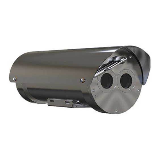
Flame Proof Smart IR Camera
Housings & Pan Tilt Units
Installation & Maintenance Instructions
This manual should be read before attempting to connect or operate the equipment
This equipment shall be installed in accordance with the latest local/national codes of practice, and standards
e.g.: BS EN 60079-14:2014 Explosive atmospheres – Part 14: Electrical installations design, selection and erection
Whilst every effort has been made to ensure that all information in this document is correct at the time of
publication, due to our policy of continuous improvement, the company reserves the right to change any
information contained herein without notice or reference.
With the exception to Annexe B which must be referred to the certification Body.
OXALIS
Unit B Sutton Park Way
Oddicroft Lane, Sutton in Ashfield
NG17 5FB
Tel: +44 (0)1623 444400
XP & XF
IECEx/ATEX Certified
II 2 G Ex db IIC
II 2 D Ex tb IIIC
(IEC 60079-14:2013)
ISS.A TM410 XF-XP40B SMART IR ATEX/IECEX
Advertisement
Table of Contents

Subscribe to Our Youtube Channel
Related Manuals for Eaton XP Series


Summary of Contents for Eaton XP Series
- Page 1 OXALIS ISS.A TM410 XF-XP40B SMART IR ATEX/IECEX Unit B Sutton Park Way Oddicroft Lane, Sutton in Ashfield NG17 5FB Tel: +44 (0)1623 444400 XP & XF Flame Proof Smart IR Camera Housings & Pan Tilt Units IECEx/ATEX Certified II 2 G Ex db IIC II 2 D Ex tb IIIC Installation &...
-
Page 2: Amendment Record
EATON Installation & Maintenance Instructions ISS.A TM410 XF-XP40B SMART IR ATEX/IECEX Amendment Record Issue Date Details of Amendment 07/02/2024 First Issue... -
Page 3: Table Of Contents
Recommended Tools ..........................6 Recommended Spares .......................... 6 Installation ..............................6 Unpacking.............................. 6 Handling ..............................6 Mounting ............................... 7 3.3.1 Mounting the XP Series ......................... 7 3.3.2 Mounting the XF Series ......................... 9 Accessory Installation .......................... 10 3.4.1 Sunshield Installation .......................... 10 3.4.2 Washer Nozzle Installation ........................ -
Page 4: General
A readily accessible disconnection device shall be incorporated in the electrical installation wiring, to provide all pole isolation of the supply to the equipment. Only use tools and replacement parts supplied or recommended by EATON. This unit does not contain any user serviceable parts. -
Page 5: Description
XF series, fixed camera housings. XP series, P&T units with integral pan and tilt shafts and a fixed base section for cable connection. Each of the above contain an integrated smart illuminator. The XF series fixed housings comprise a single tube section with either 3 cable entries in the rear cover or 1 in the side (model dependent). -
Page 6: Versions
EATON Installation & Maintenance Instructions ISS.A TM410 XF-XP40B SMART IR ATEX/IECEX Versions There are various camera configurations available within the range; these include Day/Night cameras with optional wiper, integral washer or external washer, Thermal Imager and Dual Camera Day/Night and Thermal units. -
Page 7: Mounting
It is strongly suggested that the EATON range of mounting brackets are used 3.3.1 Mounting the XP Series The XP pan/tilt/housing assembly may be mounted onto various structures such as bulkheads, walls or towers, it can be mounted in the inverted position, but this must be specified upon order. - Page 8 EATON Installation & Maintenance Instructions ISS.A TM410 XF-XP40B SMART IR ATEX/IECEX Fig.1 XP40VE Smart IR - Example XP Series unit showing base mount fixing points Fig.2 Example mounting bracket: BPW6500 Wall Bracket...
-
Page 9: Mounting The Xf Series
The type and size of these fixings to be supplied by the user/installer and must be suitable for the specific installation requirements. To gain flexibility of the cameras view direction one of the EATON is needed, these comprise of the BFP00SW Swivel joint (Fig 4), the BFW32SW (Fig 5) a combination of the BFW5000 and BFP00SW. -
Page 10: Accessory Installation
EATON Installation & Maintenance Instructions ISS.A TM410 XF-XP40B SMART IR ATEX/IECEX Fig.5 BFW32SW Swivel Joint & Pole Adaptor Accessory Installation 3.4.1 Sunshield Installation Sunshields are supplied uninstalled to prevent damage during shipping and unpacking. They are supplied with a protective white film that must be removed prior to installation. - Page 11 EATON Installation & Maintenance Instructions ISS.A TM410 XF-XP40B SMART IR ATEX/IECEX Fig.6 Type A Sunshield Installation Fig.7 Type B Sunshield Installation...
-
Page 12: Washer Nozzle Installation
EATON Installation & Maintenance Instructions ISS.A TM410 XF-XP40B SMART IR ATEX/IECEX 3.4.2 Washer Nozzle Installation A continuous rotation P&T system, if supplied with an external washer unit, is supplied with a suitable washer nozzle and mounting bracket. These should be fitted during installation with the supplied fixing and positioned to allow cleaning fluid to reach the camera housing window when the wash command is sent. -
Page 13: Electrical Installation
EATON Installation & Maintenance Instructions ISS.A TM410 XF-XP40B SMART IR ATEX/IECEX Electrical Installation Electrical installation and servicing should only be carried out by qualified service personnel and in accordance with all local/national codes of practice and standards e.g. EN 60079- 14:2014 and IEC 60079-14:2013. -
Page 14: Xp Common Connection Examples
EATON Installation & Maintenance Instructions ISS.A TM410 XF-XP40B SMART IR ATEX/IECEX 3.5.2 XP Common Connection Examples Always refer to project specific drawings and information... -
Page 15: Electrical Installation Xf Series Units
EATON Installation & Maintenance Instructions ISS.A TM410 XF-XP40B SMART IR ATEX/IECEX 3.5.3 Electrical Installation XF Series Units Cable entry type to the housing will be via 1 x M20 x 1.5 ISO entry at the side adaptor of the housing, or via the 3x M20 cable entry end cover on the rear of the housing, solely for connection of power and signal wiring, no internal user wiring is allowed in this unit.(Fig 11, 12 &... -
Page 16: Xf Common Connection Examples
EATON Installation & Maintenance Instructions ISS.A TM410 XF-XP40B SMART IR ATEX/IECEX 3.5.4 XF Common Connection Examples (Above) Example of Alternate FIXED camera common connections for 24 V Models. -
Page 17: Maintenance
In the event of ferrous deposits, the units should be cleaned immediately following EATON guidelines. In atmospheres that are high in corrosive particles the units should be cleaned every 3 to 4 months using only EATON recommended cleaning products and procedures. -
Page 18: Op Pr Enclosure Label
EATON Installation & Maintenance Instructions ISS.A TM410 XF-XP40B SMART IR ATEX/IECEX OP PR Enclosure Label... -
Page 19: Specifications, Technical Data & Special Conditions For Safe Use
EATON Installation & Maintenance Instructions ISS.A TM410 XF-XP40B SMART IR ATEX/IECEX Specifications, Technical data & Special conditions for safe use. Coding IECEx & ATEX II 2 G Exdb IIC T6-3*Gb -##°C ≤ Ta ≤ +##°C II 2 D Ex tb IIIC T135°C Db IP66/67 Fibre Optic II 2 G Exdb op pr IIC T6…3*Gb -##°C ≤... -
Page 20: A Ex Annex
EATON Installation & Maintenance Instructions ISS.A TM410 XF-XP40B SMART IR ATEX/IECEX A Ex Annex Special Conditions of Certification Specific Conditions for Safe Use. No modifications must be made to the flame paths of the unit without consultation of the drawings listed on the schedule. - Page 21 EATON Installation & Maintenance Instructions ISS.A TM410 XF-XP40B SMART IR ATEX/IECEX The test conditions shall be such that the stresses are comparable to those to which these parts are exposed in the complete enclosure. If required during the construction, thread inserts needs to withstand the routine overpressure test also.
Need help?
Do you have a question about the XP Series and is the answer not in the manual?
Questions and answers