EASTERN INSTRUMENTS CENTRIFLOW Installation & Operation Manual
Hide thumbs
Also See for CENTRIFLOW:
- Installation & operation manual (78 pages) ,
- Quick start manual (3 pages) ,
- Manual (93 pages)
Table of Contents
Advertisement
Quick Links
CENTRIFLOW
DIGITAL ELECTRONICS
®
INSTALLATION & OPERATION
MANUAL
REV 6/23
VERSION cM3.0.0 SOFTWARE
[cM3.0.0 Software for use with cMT3072XH HMI]
ORIGINAL LANGUAGE
Copyright© 2023 Eastern Instrument Laboratories, Inc.
All Rights Reserved
416 Landmark Drive
Phone:(910) 392-2490
www.easterninstruments.com
Wilmington, NC 28412
Fax: (910) 392-2123
Advertisement
Table of Contents

Related Manuals for EASTERN INSTRUMENTS CENTRIFLOW


Summary of Contents for EASTERN INSTRUMENTS CENTRIFLOW
- Page 1 CENTRIFLOW DIGITAL ELECTRONICS ® INSTALLATION & OPERATION MANUAL REV 6/23 VERSION cM3.0.0 SOFTWARE [cM3.0.0 Software for use with cMT3072XH HMI] ORIGINAL LANGUAGE Copyright© 2023 Eastern Instrument Laboratories, Inc. All Rights Reserved 416 Landmark Drive Phone:(910) 392-2490 www.easterninstruments.com Wilmington, NC 28412...
-
Page 2: Table Of Contents
TABLE OF CONTENTS SAFETY Safe Operation ......................4 Warnings and Cautions ....................4 Safety Placards ......................5 INSTALLATION Installation Requirements ....................6 Trouble Areas .......................6 Electronics Enclosure Drawing ..................7 OPERATION Identifying Your Components..................8 Powering On .........................9 Screen Saver .......................11 Security Features ......................12 Logging On ....................12 Changing Your Password ................13 PROCEDURES Static Calibration ......................14... - Page 3 TABLE OF CONTENTS SCREEN GUIDE 19. HMI Screen Guide .....................33 TOP ........................33 TOP.RUN ........................34 TOP.CAL........................35 TOP.COM ........................36 TOP.SET ........................37 TOP.I/O ........................38 TOP.OPT .........................39 TOP.PRF ........................40 CAL.ZERO ........................41 CAL.CALs .........................42 CAL.CALd ........................43 CAL.RANGE ......................44 CAL.INHIBIT ......................45 CAL.FILTER ......................46 COM.INFO ......................47 COM.IP ........................48 SET.RATIO .......................49 SET.FS.MODIFY .......................50 SET.FIELD ........................51...
-
Page 4: Safety Safe Operation
• Use the appropriate Personal Protection Equipment as required for operating the meter within its installation location. • The various surfaces of the CentriFlow Meter module may have sharp edges and have the potential to cause injury. Use the proper protection for your hands when servicing or maintaining your CentriFlow Meter. -
Page 5: Safety Placards
SOME OR ALL OF THESE WARNINGS MAY BE ON YOUR METER. BE AWARE OF THE POSSIBLE DANGERS PRESENT. ELECTRICAL SERVICE Electrical shock or electrocution is possible when servicing the electronics of any Eastern Instruments equipment. Be sure to disconnect power before conducting any repairs on the elec- tronics. PRODUCT FLOW The Control Valve for the CentriFeeder is used only as a control valve and does not act as an isolation valve. -
Page 6: Installation
• The Electronics Enclosure should be wired using only the factory cable. There is a standard 25’ Remote Electronics Cable supplied with the CentriFlow® Meter. The Electronics Cable should be cut to the exact length required. Do not coil the cable inside the meter casing or within the electronics cabinet. -
Page 7: Trouble Areas
Isolate both power and signal lines from each other at all times. • The CentriFlow® Meter is balanced at a specific angle and should not be subject to vibration or movement. The mass of the mount should be at least 2 times the mass of the meter . -
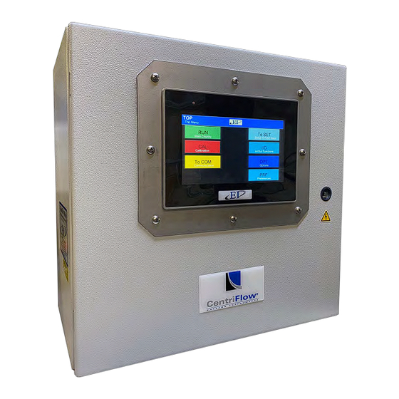
Page 8: Electronics Enclosure Drawing
Electronics Enclosure Drawing Dimensional Drawing • Shown here with optional HMI cover installed. 416 Landmark Drive Phone:(910) 392-2490 www.easterninstruments.com Wilmington, NC 28412 Fax: (910) 392-2123... -
Page 9: Operation
POWER CONNECTIONS LABEL ENCLOSURE DOOR WITH CIRCUIT BREAKERS GROUND CONNECTION The Digital Electronics Enclosure contains the HMI, the Digital CentriFlow® Electronics (DCE), Power Supply, Alarm Relay, Power Connections with Circuit Breakers, and the Customer Con- nections. 416 Landmark Drive Phone:(910) 392-2490 www.easterninstruments.com... -
Page 10: Powering On
Powering On To power on your digital electronics, open the Digital Electronics Enclosure and close the Cir- cuit Breakers on the VAC Power wiring connections as shown below. Circuit Breakers Close the Digital Electronics Enclosure. The HMI should now be coming on. Upon startup, the HMI will display the Main Menu Screen, also called TOP, as shown below. -
Page 11: Screen Saver
Screen Saver Please note that the ScreenSaver option will be enabled upon shipment. If any page is left un- disturbed for 120 minutes, the ScreenSaver will be enabled. The ScreenSaver will look like the image below. To stop the ScreenSaver, press anywhere on the screen. To disable the ScreenSaver option, from the TOP MENU, press the PRF Button and then, the SCREEN SAVER Button. -
Page 12: Security Features
Security Features Your CentriFlow® HMI is equipped with a security system that allows sensitive information and settings for your process to be protected via a password-based security layer. The password- based security system is designed to protect your information and settings from unauthorized access and tampering. -
Page 13: Changing Your Password
After correctly entering your username and password, you will be logged on to the system. Please note that you will be required to log in any time the HMI unit is powered up. CHANGING YOUR PASSWORD The password-based security system of your HMI was designed to have a similar look and feel to computer-based security systems commonly encountered on a PC. -
Page 14: Procedures
PROCEDURES Static Calibration (Static Cal.) Static Calibration sets the Range of the Transducer in the CentriFlow Meter. This allows the meter to be versatile in a way such that it can be ranged up, known as Extended Static Calibra- tion, or it can be ranged down, known as Reduced Static Calibration. The Static Calibration is a Factory Setting and should not need to be changed while the meter is in service, unless the Transducer has been replaced. - Page 15 Step 5: Press the CALs Button. You should now be on the CAL.CALs page as seen to the right. Step 6: Hang the Test Weight provided with the Electronics Enclosure from the Calibration Stud located under the bottom edge of the Pan as seen below.
-
Page 16: Site Calibration
Site Calibration When the CentriFlow® Meter is shipped from the factory, it is programmed with Default val- ues for the Static Calibration and the Calibration Voltage, which were chosen for the particular material being measured with the meter. As described in the previous Section, the Static Cali- bration is an adjustment that ranges the Transducer, the Measurement Element of the meter. - Page 17 Site Calibration Continued Step 3: After product has stopped flowing through the meter, go to the SET.FIELD page locat- ed under the TO SET option on the MAIN MENU. HINT: Access the MAIN MENU and then press TO SET, and finally, FIELD DATA. Step 4: Click on the “ENTER RUN”...
- Page 18 Site Calibration Continued Step 7: Return to the TOP.RUN page and press the RESET Button on the bottom left. To reset your total to 0. Step 8: Repeat Steps 2-7 four more times to complete the five Field Data runs. Please note: Check your data to ensure your runs are repeatable.
- Page 19 Step 10: Now return to the TOP.SET page by returning to the MAIN MENU and pressing the TO SET Button. Step 11: Now press the FIELD CALd Button. Step 12: You should now be on the SET.FIELD page. The newly calculated Dynamic Calibration can be seen on the left side of the page, while the current Dynamic calibration can be seen on the right side of the screen.
-
Page 20: Alarm Rate
Alarm Rate The alarm relay can be used to trigger alarms which warn the operator that a batch is com- plete or that the rate has exceeded a set speed. To use the alarm function of your Digital Elec- tronics Package, please make sure that the alarm relay is wired according to the diagram in the Wiring Customer Connections-Alarm Outputs section of the Wiring Manual. - Page 21 Step 4: You should now be on the I/O.RATE.SP page. Details of this page can be found in the HMI Screen Guide in this manual. Step 5: Press the RATE TARGET Button. A Numeric Keypad will appear. Please enter your rate target into the keypad and press ENTER.
-
Page 22: Alarm Totalization
Alarm Totalization The alarm relay can be used to trigger alarms which will either hold for a period of time after a set Total has been reached, or will latch indefinitely until the Total is reset. To use the alarm function of your Digital Electronics Package, please make sure that the alarm relay is wired ac- cording to the diagram in the Wiring Customer Connections-Alarm Outputs section of the wir- ing manual. - Page 23 Step 6: Press the OK Button. You should now be back on the I/O.WEIGHT.OUT page. Step 7: You should now choose which type of Weight Output you would like to use. Press the OUTPUT TYPE Button for your options. A popup should appear. More infor- mation on the two types of Weight Output (Pulse and Latch), can be found on the I/O.WEIGHT.OUT page in the Screen Guide section of the manual.
- Page 24 Remote Reset & Zero Capability What is Remote Reset? Remote Reset allows you to remotely trigger a reset of the Totalization on your Digital Electronics. This feature is similar to pressing the RESET Button from the TOP.RUN page. The Remote Reset can be used by installing a remote push button on/off switch (customer sup- plied).
- Page 25 Weighted Count Output (Optional) What is Weighted Count? Weighted Count is an output option that will allow you to generate a count much slower than the 500 Hz Frequency, flow rate proportional signal. It is derived mathematically by dividing the totalization output by a scale factor. Once a target weight is selected, a pulsed output sig- nal is generated by the electronics each time the target weight is reached.
- Page 26 Pulsed Air System (Optional) ® *If the CentriFlow Meter was shipped with the Pulsed Air option please continue with the following directions.* PURPOSE: The Pulsed Air System was designed to deliver a pulsed blast of air to the area in front of the Backplate and behind the Tangential Cover, as well as across the Measurement Pan.
-
Page 27: Ma Filter
4-20 mA Filtering Filtering of the 4-20 mA signal allows smoothing of the otherwise instantaneous output delivered by the CentriFlow Meter’s electronics. The 4-20 mA signal can be filtered from 1/4s up to 10s increments, however the mathematical method of filter- ing differs depending on the desired incre- ment. - Page 28 Software Setup of the 4-20 mA Filter The 4-20 mA filter allows local filtering of the 4-20 mA flow rate signal and can be filtered us- ing 1/4s increments up to 10s increments. Please note that the 4-20 mA Filter cannot be transmitted via Remote Communications Protocol.
-
Page 29: Rate Filter
Filtering of the rate as seen on the TOP.RUN allows smoothing of the otherwise instantaneous output delivered by the CentriFlow Meter’s electronics. The filtering method is similar to the 4 -20 mA Simple Moving Average filter with some specific differences. Whereas the 4-20 mA filter is a local filter only, the Rate Filter allows filtering of the output that is transmitted via Ethernet or any other Internet Protocol. -
Page 30: Changing The Ip Address
Changing the Ethernet/IP Address (Optional) Example of Establishing Communication : ContrlLogx Unit If you have purchased the Ethernet/IP Option, read on for the procedure to set up your IP Address to communicate with your existing PLC. The Ethernet/IP option allows you to output both the flow rate and the totalization signals via an Ethernet connection, directly to your PLC. - Page 31 DATA/COMMANDS RECIEVED BY PLC FROM HMI TAG NAME DIRECTION FUNCTION Rate_2000 HMI to PLC Flow Rate Total_2000 HMI to PLC Totalization Zero_rdbk_2000 HMI to PLC Read back register for the Remote Zero command Read back for Remote Product (Number of Prod- mCAL_rdbk_2000 HMI to PLC uct: Multiple Cal.
- Page 32 Protocol Selection (EI01) If the Meter EI01 protocol is selected, then the tag names have a _EI01 suffix, where EI01 is a gener- ic four-digit number. This may be useful in a single or dual meter installation to help simplify the PLC programming.
- Page 33 NOTE: Reset output functions similarly to pressing the Reset Button on the TOP.RUN page, while the Multiple Cal output functions similarly to using the multiple calibration option detailed in the Setup of Multiple Calibration section of this manual. PLC Programming Note: Remote RESET: (Valid values) 0 for normal operation 1 to reset the total...
- Page 34 NOTE: Please enter all tags into the PLC configuration. Missing tags may affect system performance. 416 Landmark Drive Phone:(910) 392-2490 www.easterninstruments.com Wilmington, NC 28412 Fax: (910) 392-2123...
- Page 35 Step 3 (PLC): From the Controller Properties window for your PLC, click on the System Proto- col tab. Verify that the following settings have been applied: • Protocol: DF1 Point to Point • Station Address: Default is 0 • Error Detection: BCC Step 4 (PLC): Double-click on the Ethernet module folder and note the IP address that is as- signed to the module.
- Page 36 Step 5 (HMI): Enter the IP Address of the PLC EtherNet module into the HMI OPT.PLC page. Please note that the CPU Slot is hard coded to the value of 0. If anoth- er value is required, EI will change the software to accept your CPU Slot val- ue.
- Page 37 Communication can be toggled from the PLC control page OPT.PLC. To reach that page, please see the below page progression. ETHERNET/IP Please note that if PLC Communication is enabled, data is only transmitted via Ethernet while on the Main Run screen or TOP.RUN page. The TOP.RUN Screen is accessed by travelling to the page only.
-
Page 38: Setup Of Multiple Calibration
Setup of Multiple Calibration Screens The Multiple Calibration Screens option allows you to run more than one product through your meter without having to recalibrate each time the product is switched. This option allows you to store up to eight product calibrations at one time. To access the option, press the MULTIPLE CAL Button from the TOP.OPT page, accessed by pressing the OPTIONS Button from the TOP Menu. - Page 39 Step 1: (Continued) Selecting the product above will allow you to rename the selected product. Although this step is not necessary to continue it will help you differenti- ate your products and their calibration voltages in the future. Step 2: To assign a new calibration name, the name of the product itself is typically used, however any name can be used.
- Page 40 Step 5: To manually enter a Dynamic Calibration, return to the main TOP Menu, press the CAL Button, and then press the CALd Button. You should now see this screen (right). Click the current value for Dynamic Calibration (yellow button) and enter your new value.
-
Page 41: Web Server
Web Server EasyWeb and WebView The WebView feature enables viewing and interacting with your HMI screens in a web browser. This section describes how to set it up. Connecting to WebView: To connect to WebView all you need is a device that has a web browser and has access to the HMI’s IP address. - Page 42 Web Server EasyWeb and WebView • To connect to WebView: 5. After logging in, you’ll see the EasyWeb 2.0 system dashboard. Select WebView within ‘admin.’ 6. Select Control Mode. Enter the default password 111111. Click Log in. Selecting ‘Control Mode’ Here 416 Landmark Drive Phone:(910) 392-2490 www.easterninstruments.com...
-
Page 43: Hmi Software Update
HMI Software Update The following section explains how to download a project file by using USB drive. Downloading a new project is a way of updating your HMI program which allows for function/feature updates as well as Ethernet Tag name updates. This is especially useful for multiple meter installations where all meter's tags will have to have different Ethernet Tag names. - Page 44 HMI Software Update Continued 4. Next, click the folder Icon in the Project field, it will show the directories in the external device. (usbdisk: USB Drive) 5. Select the directory that contains the project. 6. Select the project and press OK to start downloading the new project. 416 Landmark Drive Phone:(910) 392-2490 www.easterninstruments.com...
-
Page 45: Screen Guide
SCREEN GUIDE Every HMI page has a unique name that includes the previous page name combined with a de- scription of the current page. A period separates the names. When the DCE is first powered on, or when you press the TO TOP Button on another page, the TOP page is displayed. TOP is the Main Menu screen. -
Page 46: Top.run
TOP.RUN TOP.RUN is the main display mode. Access this screen by pressing the RUN Button from the TOP screen. A Horizontal Bar Graph is used for a graphical indication of flow rate. The length of the green horizontal bar is proportional to the flow rate. To determine the flow rate, use the scale just below the horizontal bar. -
Page 47: Top.cal
TOP.CAL TOP.CAL is the Main Calibration Page. Access this screen by pressing the CAL Button from the TOP page. There are six buttons on the TOP.CAL page. ZERO: Press the ZERO Button to go to the CAL.ZERO page. This is where you can perform a Zero Calibration. -
Page 48: Top.com
TOP.COM TO COM TOP.COM is the Main Communication Page. Access this page by pressing the COM Button from the TOP page. There are two buttons on the TOP.COM page. INFORMATION: Press the INFORMATION Button to view information concerning your Software’s version, your IP Address, and your main configuration settings. -
Page 49: Top.set
TOP.SET TO SET TOP.SET is the Main Data Entry menu. Access this page by pressing the SET Button from the TOP page. There are five buttons on the TOP.SET page. MODEL: Change the meter model. When the MODEL Button is pressed, a popup appears which allows you to scroll through the meter models that are available. -
Page 50: Top.i/O
TOP.I/O TOP.I/O is the Main Input/Output Menu page. Access this screen by pressing the I/O Button from the TOP page. There are three buttons on the TOP.I/O page. This page is for accessing all options associated with setting all inputs and outputs in your process. ALARM: Set up and configure the alarms. -
Page 51: Top.opt
TOP.OPT TOP.OPT is the Main Options page. Access this screen by pressing the OPT Button from the TOP page. There are 3 options that can be adjusted here. The options accessed from this page are listed below. MULTIPLE CAL: Set up and configure the Multiple Calibration option after pushing this button. -
Page 52: Top.prf
TOP.PRF is the Main Preferences page. Access this screen by pressing the PRF Button from the TOP page. There are 6 preferences that can be adjusted here. The TOP.PRF page allows access to several features that offer greater flexibility during the operation of the CentriFlow Meter. The features accessed from this page are listed below. -
Page 53: Cal.zero
CAL.ZERO ZERO CAL.ZERO is the Zero Calibration page. Access this screen by pressing the ZERO Button on the TOP.CAL screen after pressing the CAL Button from the TOP page. This page is for conducting Zero Calibrations. The procedure for a Zero Calibration can be found under the Static Calibra- tion Section. -
Page 54: Cal.cals
CAL.CALs CALS CAL.CALs is the Static Calibration page. Access this screen by pressing the CALs Button on the TOP.CAL page after pressing the CAL Button from the TOP page. This page is for conducting Static Calibrations. The procedure for a Static Calibration can be found under the Static Cali- bration Section. -
Page 55: Cal.cald
CAL.CALd CALD CAL.CALd is the Dynamic Calibration page. Access this screen by pressing the CALd Button on the CAL Screen after pressing the CAL Button from the TOP page. This page is for conducting Dynamic Calibration. Please see the Dynamic Calibration (or Site Calibration) procedure in this manual. -
Page 56: Cal.range
CAL.RANGE RANGE CAL.RANGE is the Calibration Range page. Access this screen by pressing the RANGE Button on the TOP.CAL page after pressing the CAL Button from the TOP page. This page is for changing the Range of your electronics. The Range can be changed to the desired value by clicking on the appropriate button. The Range setting is already selected by the factory and typically adjustment is not required. -
Page 57: Cal.inhibit
CAL.INHIBIT INHIBIT CAL.INHIBIT is the Inhibit page. Access this screen by pressing the INHIBIT Button on the TOP.CAL page after pressing the CAL Button from the TOP page. This page is for changing the Inhibit that sets a threshold which the Flow Rate Output must rise above for the electronics to begin counting. -
Page 58: Cal.filter
CAL.FILTER FILTER CAL.FILTER is the Filter page. Access this screen by pressing the FILTER Button on the TOP.CAL page after pressing the CAL Button from the TOP page. This page is for selecting the number of points used in the 4-20mA moving average filter. The filter will be a simple moving average filter for filtering up to three seconds and will be an exponential moving average for filtering three seconds or over. -
Page 59: Com.info
COM.INFO TO COM INFORMATION This screen is accessed when the INFORMATION Button is pushed from the TOP.COM page. This page can be accessed to view information regarding the software version for your particu- lar unit as well as your current communication protocol information. 416 Landmark Drive Phone:(910) 392-2490 www.easterninstruments.com... -
Page 60: Com.ip
COM.IP TO COM IP CONFIGURATION This screen is accessed when the IP CONFIGURATION Button is pushed from the TOP.COM page. This page can be accessed to enter or change your IP Address. Please note that each section of the IP address must be pressed and the new value entered via a popup keypad. All for sections are entered independently. -
Page 61: Set.ratio
SET.RATIO TO SET CALCULATE DEFAULT SET.RATIO is the page that allows you to calculate your count per weight ratio. The C/W Ratio, or Count per Weight Ratio, is determined by the factory. This value is the divisor used to calcu- late the engineering count (total) from the raw count. -
Page 62: Set.fs.modify
SET.FS.MODIFY TO SET FULL SCALE MODIFY SET.FS.MODIFY is the page that allows you to modify your full scale. Pressing the ELECTRON- ICS FULL SCALE Button opens a list of possible Full Scales that you can choose from. Select your Full Scale value and press the SET RATIO Button in the upper right hand corner. ELECTRONIC FULL SCALE BUTTON... -
Page 63: Set.field
SET.FIELD TO SET FIELD DATA SET.FIELD is the page that allows you to collect and verify your site calibration data. This page is used extensively in Site Calibration as shown in the Site Calibration section of this manual. This screen allows you to compare the metered weight of material run through the meter ver- sus the actual weight of the material, often weighed by a static scale after being diverted. -
Page 64: Set.cald
SET.CALd TO SET FIELD CALD SET.CALd is a page used in conjunction with SET.FIELD page to adjust your Dynamic Calibration using recently collected field data. Once the field data is entered, open this page and you should see the new calculated Dynamic Calibration value under the CALCULATED DYNAMIC CALIBRATION SETTINGS section. -
Page 65: I/O.alarm
I/O.ALARM ALARM I/O.ALARM is the Alarm page. Access this screen by pressing the ALARM Button from the TOP.I/O page. This page is for changing the options of the alarm. The alarm can be turned on and off using the ALARM ENABLE Button. Press the ALARM ENABLE Button until the desired result is displayed in the Button’s display box. -
Page 66: I/O.rate.sp
I/O.RATE.SP ALARM ENTER ALARM TARGET I/O.RATE.SP is the Alarm Target Entry page. Access this screen by pressing the TARGET Button from the I/O.ALARM page while ALARM TYPE Rate is selected. This page is for changing the values that will trip the alarm. You can enter a rate by pressing the RATE TARGET Button (yellow button) and entering a rate into the popup keypad. -
Page 67: I/O.weight.out
I/O.WEIGHT.OUT ALARM ENTER ALARM TARGET I/O.WEIGHT.OUT is the page that allows you to define the type of Weight/Totalization alarm that you will be using. Access this screen by first pressing the I/O Button from the TOP.MENU page. Then press the ALARM Button, followed by the ENTER ALARM TARGET Button (only available if WEIGHT has been selected as the ALARM TYPE). - Page 68 I/O.WCOUNT WEIGHTED COUNT The I/O.WCOUNT page allows you to set up the weighted count option. This option allows you to set a target weight that will trigger a pulsed signal each time that target weight passes over the meter. The WEIGHTED COUNT TARGET Button allows you to determine when the pulse will trigger by selecting the target weight, while the PULSE WIDTH Button allows you to determine the length, or duration, of the pulse signal.
-
Page 69: Opt.plc (Optional)
OPT.PLC (Optional) ETHERNET/IP This screen is accessed when the ETHERNET/IP Button is pushed from the TOP.OPT page. The TOP.OPT page is accessed by pushing the OPTIONS Button from the Main Menu. Pushing the buttons on this menu allows you to Enable or Disable local control of the electronics and al- lows you to change your IP address. -
Page 70: Cycle Time
OPT.PULSEDAIR PULSED AIR This screen is accessed when the PULSED AIR Button is pushed from the TOP.OPT page. The TOP.OPT page is accessed by pushing the OPTIONS Button from the Main Menu. From this screen you can enable and disable the pulsed air option, change the frequency of the blasts of air, set Lock Out Time, and perform a manual test of the Pulsed Air System. -
Page 71: Reference
REFERENCE Definition of Terms Dynamic Calibration (CALd): Setting that adjusts the Calibration of the Electronics so that 100% Output is equal to the Electronic Full Scale Flow Rate (Mass). This number ranges from a minimum of 4 to a maximum of 10. Electronic Full Scale Flow Rate (Mass): Flow Rate that Electronics is calibrated at such that the Electronics output is 100%. - Page 72 Static Calibration (CALs): Voltage setting that Ranges Transducer in a STATIC State. This setting is made while the Test weight is hung from the Calibration Stud on the Pan End and no product is on the Pan. Weighted Count: The weighted count is the engineering unit count divided by a scale factor to generate a much slower count (i.e.
- Page 73 416 Landmark Drive Phone:(910) 392-2490 www.easterninstruments.com Wilmington, NC 28412 Fax: (910) 392-2123...
- Page 74 416 Landmark Drive Phone:(910) 392-2490 www.easterninstruments.com Wilmington, NC 28412 Fax: (910) 392-2123...
Need help?
Do you have a question about the CENTRIFLOW and is the answer not in the manual?
Questions and answers