EASTERN INSTRUMENTS CentriFlow Manual
Centrifeeder electronics for use with centrifeeder with integrated control valve (icv) or auxiliary feeder
Hide thumbs
Also See for CentriFlow:
- Installation & operation manual (78 pages) ,
- Quick start manual (3 pages) ,
- Installation & operation manual (74 pages)
Table of Contents
Advertisement
Quick Links
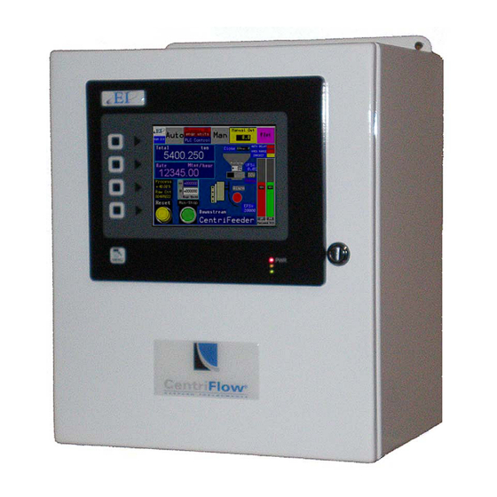
CENTRIFEEDER ELECTRONICS
FOR USE WITH CENTRIFEEDER with Integrated Control Valve (ICV)
or AUXILIARY FEEDER
REV 4/17
VERSION 6.5.0 SOFTWARE
Copyright© 2017 Eastern Instrument Laboratories, Inc.
All Rights Reserved.
416 Landmark Drive
Phone:(910) 392‐2490
www.easterninstruments.com
Wilmington, NC 28412
Fax: (910) 392‐2123
Advertisement
Table of Contents

Related Manuals for EASTERN INSTRUMENTS CentriFlow


Summary of Contents for EASTERN INSTRUMENTS CentriFlow
- Page 1 CENTRIFEEDER ELECTRONICS FOR USE WITH CENTRIFEEDER with Integrated Control Valve (ICV) or AUXILIARY FEEDER REV 4/17 VERSION 6.5.0 SOFTWARE Copyright© 2017 Eastern Instrument Laboratories, Inc. All Rights Reserved. 416 Landmark Drive Phone:(910) 392‐2490 www.easterninstruments.com Wilmington, NC 28412 Fax: (910) 392‐2123...
-
Page 2: Table Of Contents
TABLE OF CONTENTS SAFETY Safe Opera on ......................... 4 Warnings and Cau ons ....................4 Safety Placards ........................ 5 INSTALLATION 1. Installa on Guidelines ....................6 Requirements ........................ 6 Trouble Areas ........................ 6 Electronics Enclosure Drawing ..................7 Iden fying Your Components: Electronics ..............8 Iden fying Your Components: CentriFeeder with ICV .......... - Page 3 14. Filling Mode Using an Auxiliary Feeder ................46 15. Se ng the Alarm ‐ Rate ....................48 16. Se ng the Alarm ‐ Totaliza on ..................50 17. Setup of Remote Reset Capability .................. 52 18. Using the Compact Flash ....................53 Removing the Flash Card ....................
-
Page 4: Safety
Check for damaged parts before opera ng the meter. Any damaged part should be properly repaired or replaced by trained personnel. Do not operate the meter if any com‐ ponent does not appear to be func oning correctly. Contact Eastern Instruments for assis‐ tance or for repair components. -
Page 5: Safety Placards
SOME OR ALL OF THESE WARNINGS MAY BE ON YOUR METER. BE AWARE OF THE POSSIBLE DANGERS PRESENT. ELECTRICAL SERVICE Electrical shock or electrocu on is possible when servicing the electronics of any Eastern Instruments equipment. Be sure to disconnect power before conduc ng any repairs on the elec‐ tronics. PRODUCT FLOW The Control Valve for the CentriFeeder is used only as a control valve and does not act as an isola on valve. -
Page 6: Installation
INSTALLATION INSTALLATION REQUIREMENTS The meter is to be used in a loca on where the product can be dropped from a fixed height such as a conveyer, or any type of feed system, which will give a reasonably constant ini al ver cal velocity. The design of the meter requires the product to contact the Tangen al Plate and have some ver cal drop. -
Page 7: Electronics Enclosure Drawing
Electronics Enclosure Dimensional Drawing Phone:(910) 392‐2490 416 Landmark Drive www.easterninstruments.com Fax: (910) 392‐2123 Wilmington, NC 28412... -
Page 8: Iden Fying Your Components: Electronics
Iden fying Your Components: Electronics The Digital Electronics Enclosure contains the HMI, the Digital CentriFlow® Electronics (DCE), Power Supply, Alarm Relay, Power Connec ons with Knife Disconnects, and the Customer Connec ons. 416 Landmark Drive Phone:(910) 392‐2490 www.easterninstruments.com Fax: (910) 392‐2123... -
Page 9: Iden Fying Your Components: Centrifeeder With Icv
Iden fying Your Components: CentriFeeder with ICV INTEGRATED CONTROL VALVE AMPHENOL CONNECTOR FOR TRANSDUCER VALVE CABLE (BLACK) SENSOR CABLE (WHITE) AMPHENOL CONNECTORS METER MODULE MEEASUREMENT PAN ENCLOSURE Please be sure to ground the Wago Connector for the Transducer. To do so, run your ground wire, along with the Transducer Cable, through the Customer Provided Conduit and Connect to both the Meter and The Digital Electronics as shown. -
Page 10: Iden Fying Your Components: Auxiliary Control
Iden fying Your Components: Auxiliary Control WAGO CONNECTOR FOR THE TRANSDUCER 110V AC POWER FOR THE VIBRAWEIGH AMPHENOL CONNECTOR VIBRAWEIGH ELECTRONICS AND WAGO (OPTIONAL) TRANSDUCER COLUMN WIRE Please be sure to ground the Wago Connector for the Transducer. To do so, run your ground wire, along with the Remote Electronics Cable, through the Customer Provided Conduit and Connect to both the Meter and The Digital Electronics as... -
Page 11: Wiring
Basic Wiring: Wiring of the CentriFeeder™ can be broken down to the following categories: Ground the CentriFeeder Module Wiring Electronics Cable at the Meter Module Wiring the Customer Connec ons at the Electronics Enclosure Connec ng the Power Electrical Informa on: The following DCE digital signals are phototransistor outputs: ... -
Page 12: Grounding The Centrifeeder
GROUNDING THE CENTRIFEEDER A separate Earth Ground Wire (14 gauge) is required to be connected to the meter module. This ground wire is required for operator safety and for proper opera on. This ground must be sup‐ plied from the main plant ground at the service entrance. PLEASE BE SURE TO GROUND THE CENTRIFEEDER METER MODULE TO AN EARTH GROUND! www.easterninstruments.com 416 Landmark Drive... -
Page 13: Wiring The Remote Electronics Cable At Meter Module: Centrifeeder With Icv
Enclosure. The standard length is 10’ long, but it should be cut to the exact length needed. If the distance from the CentriFlow® Meter Module to the Electronics Enclosure is more than 10’, a custom length cable which may be supplied with the meter, should also be cut to fit. -
Page 14: Wiring The Remote Electronics Cable At Meter Module: Auxiliary Control
fit. Excess cable should never be coiled up and placed into the CentriFlow® Meter Module. One end of the Re‐ mote Electronics Cable will be affixed to the meter module, while the other end will be cut to length and will be wired to the Electronics Enclosure as demonstrated in the “Wiring the Digi‐... -
Page 15: Wiring Customer Connec Ons At The Electronics Enclosure
Wiring Customer Connec ons At the Electronics Enclosure Frequency Flow Rate (+) Frequency Flow Rate (OUT) Frequency Flow Rate (‐) Local Power (+) Local Power (‐) Alarm Relay (N.C. OUT) Alarm Relay (COM OUT) Alarm Relay (N.O. OUT) 4‐20 mA Loop (+) 4‐20 mA Loop (‐) EARTH GROUND Remote Reset/Zero (Switch Input) -
Page 16: Start/Stop Control: Auxiliary Feeder Only
Start/Stop Control ‐ Auxiliary Feeder only You must properly wire your auxiliary controller using the connectors shown. For this step, the terminals are wired to the indicated terminal using the appropriate 18 gauge three con‐ ductor cable (not provided). GRAY (Normally Closed) ‐... -
Page 17: Posi On Sensor - Centrifeeder With Icv
Posi on Sensor ‐ CentriFeeder with ICV only White Cable The Posi on Sensor allows the Digital Electronics to “sense” the posi on of the blade within the valve in order to determine how open or how closed it is. To wire the Posi on Sensor, use the White cable provided to wire the terminals on your Customer Connec ons to the corre‐... -
Page 18: Wiring The Remote Electronics Cable
Wiring the Remote Electronics Cable When wiring the Remote Electronics Cable to your Digital Electronics Enclosure, please match the Customer Connec ons terminals inside your Digital Electronics to the picture below. If they are different please contact EI for further instruc ons. The table below shows the correct wire color and terminal for each type of Remote Electronics Cable available. -
Page 19: Customer Connec Ons Outputs
Maximum Load Resistance = 900 ohms NOT AVAILABLE FOR CENTRIFEEDER VIB The CentriFlow® Meter Electronics is capable of outpu ng an analog signal. This signal is a 4‐ 20 mA instantaneous isolated signal. The signal output is propor onal to the Electronic Full Scale Flow Rate. - Page 20 Digital Output Power Required The CentriFlow® Meter Electronics is capable of outpu ng a Totalizing Pulse Output signal. The Frequency, Flow Rate Propor onal signal is a pulse signal and is labeled “Rate” at the CUSTOMER CONNECTION block. The frequency of the signal is 0 to 500 pulses per second.
-
Page 21: Pulsed Air (Op Onal)
Pulsed Air (Op onal) If your CentriFeeder™ is equipped with a Pulsed Blast System, you will need to supply power to the solenoid valve on the side of the meter. Using at least an 18 Gauge, 3 Conductor Cable (not provided) connect the solenoid to the CentriFeeder™ Customer Connec ons as shown. Full Wiring Diagram in back. -
Page 22: Power: Electronics Enclosure
Power ‐ Electronics Enclosure The Digital Electronics Package includes a Power Supply to convert the customer provided VAC power to 24Vdc. Please see the diagram below for wiring connec ons. WARNING: TURN POWER OFF AT SUPPLY CIRCUIT BREAKER BEFORE WIRING THE POWER TO YOUR DIGITAL ELECTRONICS PACKAGE! VAC ONLY can be connected to the Power terminals illustrated below. -
Page 23: Power Icv Control Valve: Centrifeeder With Icv Only
Power ICV Control Valve ‐ CentriFeeder with ICV only Black Cable Power must be applied to the ICV in order to allow for movement of the ICV to both open and close. To wire the Power Cord for the ICV Control Valve, use the Black cable provided to wire the terminals on your Customer Connec ons to the corresponding terminal in your Integrated Control Valve as shown below: BLACK WIRE ‐... -
Page 24: Pulse Blast System
Pulse Blast System (Op onal) ® *If the CentriFlow Meter was shipped with the Pulse Blast op on please con nue with the following direc ons.* PURPOSE: INTEGRATED TANGENTIAL PLATE CONTROL VALVE The Pulse Blast System was designed to BACKPLATE... - Page 25 INSTALLATION DIRECTIONS 1. Install the Pulse Blast Manifold into the CentriFeeder™ Pan Cover so that the Flange on the Pulse Blast Manifold lines up with the Cut Out on the Pan Cover. If the meter was shipped with the Pulsed Blast System, the Pulse Blast Manifold will already be installed. 2.
-
Page 26: A Closer Look
A Closer Look at Your HMI The main components of your HMI Touch Screen will be the Touch Screen itself, the LED Dis‐ play, the Menu So ‐Key, and So ‐Keys 1 thru 4. By pressing the Menu So ‐Key, you will be returned to the Main Menu, or TOP page. -
Page 27: Powering On
Powering On To power on your digital electronics, open the Digital Electronics Enclosure and depress the breaker pushbu ons located on the VAC Power wiring connec ons as shown below. 10 11 12 13 14 15 16 17 18 19 20 21 22 23 24 25 27 28 29 Circuit Breakers... - Page 28 If the menu page is le undisturbed for several minutes the page will automa cally switch to the TOP.Run page seen below: For more informa on on both the TOP page and the TOP.RUN page please see the HMI Screen Guide within this manual.
-
Page 29: Security Features
Security Features Your CentriFlow® HMI is equipped with a security system that allows sensi ve informa on and se ngs for your process to be protected via a password‐based security layer. The password‐ based security system is designed to protect your informa on and se ngs from unauthorized access and tampering. - Page 30 A er correctly entering your username and password, you will be logged on to the system. Please note that the HMI security system is configured to me out a er 10 minutes of inac vi‐ ty, at which me you will be required to login again. You will also be required to login any me the HMI unit is powered up.
-
Page 31: Procedures
PROCEDURES Sta c Calibra on (Sta c Cal.) Sta c Calibra on sets the Range of the Transducer in the CentriFeeder™ Meter. This allows the meter to be versa le in a way such that it can be ranged up, known as Extended Sta c Cal‐ ibra on, or it can be ranged down, known as Reduced Sta c Calibra on. - Page 32 Step 6: Hang the Test Weight provided with the Electronics Enclosure from the Calibra on Stud located under the bo om edge of the Pan as seen below. For Pans that have more than one Calibra on Stud, there should be a Test Weight for each. Some op onal pans may not have a Stud.
-
Page 33: Site Calibra On
Site Calibra on When the CentriFeeder™ Meter is sent from the Factory it is set with Default values for the Sta c Calibra on and the Calibra on Voltage, which were chosen for the par cular material being measured with the meter. As described in the previous Sec on, the Sta c Calibra on is an adjustment that ranges the Transducer, the Measurement Element of the meter. - Page 34 Step 3: A er product has stopped flowing through the meter, go to the SET.FIELD page located under the SET op on on the MAIN MENU. HINT: Press the MENU so key, then press SET, and finally, FIELD DATA. Step 4: Click on the “ENTER RUN” Bu on and you should see the GREEN value (CF Meter) change from “0.000”...
- Page 35 Step 9: Now return to the TOP.SET page by clicking on the TO SET shortcut key in the top right corner. Now press the FIELD CALd Bu on. Step 10: You should now be on the SET.CALd page. The newly calculated Dynamic Calibra on can be seen on the le side of the page, while the current Dynamic calibra on can be seen on the right side of the screen.
-
Page 36: Se Ng The Valve's Upper And Lower Limits
Se ng the Valve’s Upper and Lower Limits ‐ CentriFeeder with ICV only The valve’s upper limits (Maximum Auto Out) and its lower limits (Virtual Flow Stop) can be set from the Advanced Se ng Menu. Virtual Flow Stop Virtual Flow Stop™ is a func on of the CentriFeeder™ that allows you to manipulate the posi‐ on of the blade of the Integrated Control Valve so that flow can be stopped without closing the Integrated Control Valve completely, thus, not damaging product and minimizing damage to the leading edge of the valve and the Tangen al Back Plate as well. - Page 37 Se ng the Maximum Auto Out For an upper limit alarm, you can set the Maximum Auto Out. To do so, press the ADV Bu on from the TOP (Main Menu) page. Press the Control Modifica ons Bu on and from the ADV.CONTROL Menu press the Maximum Auto Out Bu on.
-
Page 38: Se Ng The Auto Delay
Se ng the Auto Delay Typically, the Integrated Control Valve, while in Automa c Mode, will take several seconds to “tune” in order to reach your set throughput value upon startup. In order to avoid a large overshoot the op mal method for startup is to either start in Manual Mode and enter a remembered Manual Out value, gathered through prior runs and then switch to Automa c Mode once the tuning has occurred for several seconds, or to set the Auto Delay which accomplishes this automa cally. -
Page 39: Stroking The Valve
Stroking the Valve ‐ CentriFeeder with ICV only Stroking the Integrated Control Valve is a way of se ng the posi on sensor output to corre‐ spond to the actual stroke or range of travel of the valve’s blade. Stroking the valve may be required if the electronics package is replaced or the HMI is reprogrammed, however, new installa ons will typically include a properly stroked valve that will not need to be adjusted. - Page 40 Step 2: Check your Percent Open values in the Diagnos c Window. The Percent Open values should read +104% (±0.4%) against the open stops and ‐1% (±0.2%) against the closed stops. The Maximum Live Value should be 2.0V, ±0.25V the Minimum Live value should be 0.5V, ±0.25 V.
-
Page 41: Pid Control Loop Tuning
PID Control Loop Tuning ‐ CentriFeeder with ICV only PID #1 and #2 control the ICV in what is termed a cascade control in which the control output of PID #1 becomes the set point of PID #2 , which in turn, controls the valve. Set PID #1 according to the following table for Electronic Full Scale (eFS)= 100% Meter Volumetric Full Scale (vFS). -
Page 42: Running The Centrifeeder
Running the CentriFeeder with ICV Assuming that the meter has been properly installed and calibrated, your CentriFeeder™ can be run in one of two modes which can be quickly and easily switched between even while your process is running. These two modes are Manual and Automa c. These modes can be ac‐ cessed from the main run display shown below. - Page 43 Star ng Flow Please Note: The ICV will not run if the R‐Stop Indicator is visible on the screen. The valve will only operate if there is a closure between Customer Connec ons #18 and #19 and a jumper has been installed to serve this purpose. If this jumper has been removed, or the Remote Stop is engaged, the R‐Stop Indicator will be visible onscreen.
- Page 44 AUTOMATIC Automa c Mode is a mode that enables the valve’s posi on, or output, to be changed auto‐ ma cally based on a desired process Set Point. The valve will automa cally adjust un l the Set Point is reached or maintained. MANUAL PROCESS SET BUTTON...
-
Page 45: An -Binding Func On
CHANGING BETWEEN MODES Auto to Manual You can change from Automa c Mode to Manual Mode even while in process, by pressing the Manual Bu on. The Manual Bu on should now be green, indica ng that Manual Mode is ac vated. -
Page 46: Filling Mode Using An Auxiliary Feeder
CentriFlow Meter in order to reach this target weight. If the feed device was sig‐ naled exactly when the target value was... - Page 47 You should now see the ADV.FILL page (right). Press the ENABLE Bu on in order to toggle the Fill Mode on and off. Press the CALCULATE TAR‐ GET Bu on in order to enter your filling parame‐ ters. *Please note that filling using an Auxiliary Feeder only u lizes the Manual Target Weight Correc on method.
-
Page 48: Se Ng The Alarm - Rate
Se ng the Alarm ‐ Rate To successfully u lize the alarm func on of your Digital Electronics Package, please make sure that the alarm relay is wired according to the diagram in the Wiring Customer Connec ons‐ Alarm Outputs sec on of this manual. The relay can be used to trigger alarms which warn the operator that a batch is complete or that the rate has exceeded a set speed. - Page 49 Step 6: should I/O.RATE.SP page. The Rate Target Bu on is highlighted in Yellow. You can change the Rate Target by pressing the current Rate Target value twice. The first press will outline the value in black, as shown. The second press will bring up a numeric keypad and the Target Rate can be changed.
-
Page 50: Se Ng The Alarm - Totaliza On
Se ng the Alarm ‐ Totaliza on To successfully u lize the alarm func on of your Digital Electronics Package, please make sure that the alarm relay is wired according to the diagram in the Wiring Customer Connec ons‐ Alarm Outputs sec on in Chapter 1 of this manual. The relay can be used to trigger alarms which will either hold for a period of me a er a set Total has been reached, or will latch in‐... - Page 51 Step 6: should I/O.WEIGHT.SP page. The WEIGHT TARGET Bu on is highlighted in Yellow. You can change the Weight Target by pressing the current Weight Target value twice. The first press will outline the value in black, as shown. The second press will bring up a numeric keypad and the Target Weight can be changed.
-
Page 52: Setup Of Remote Reset Capability
Setup of Remote Reset Capability What is Remote Reset? Remote Reset allows you to remotely trigger a reset of the Totaliza on on your Digital Electronics. This feature is similar to pressing the RESET Bu on from the TOP.RUN page. The Remote Reset can be u lized by installing a remote push bu on on/off... -
Page 53: Using The Compact Flash
Using the Compact Flash Using the Compact Flash Card A 2 Gigabyte Compact Flash card is pre‐installed inside the Digital Electronics Enclosure and is located inside the enclosure on the reverse side of the HMI touch screen. Run data is stored on the Flash Drive but only when the TOP.RUN page is currently displayed. - Page 54 Save Se ngs You can also save your se ngs and configura‐ ons to your Flash Card and restore them if your se ngs have been uninten onally changed. To save your HMI se ngs to a Flash Card (provided you have one installed), press the COM Bu on from the TOP Menu to enter the TOP.COM page (seen on right).
-
Page 55: Remote Ethernet Access
Remote Ethernet Access Capabili es The preferred method for transferring data from the Compact Flash card is to link the Digital Electronics to a PC or Laptop using an Ethernet Cable. The main advantage of the remote viewing capability is that run histories can be viewed and saved from the Electronics itself to a hard drive or other desired external storage device. -
Page 56: Remote View
Entering the Digital Electronics IP Address will bring up a web page en tled “G3 Web Server”. This page will allow you access to three op ons, View Data, View Logs, and Remote View. Remote View Selec ng the Remote View op on will allow you to access the various pages of the HMI touch screen from a remote loca on. - Page 57 Clicking on any of the file names will open up the data file. These files are CSV files and typi‐ cally open into an Excel spreadsheet. Once open, the spreadsheet can be saved to another loca on such as a hard drive. A typical entry would look like the file below. The TIME column indicates the specific me, using a 24 hr clock, the count data was taken.
- Page 58 The User Se ngs Log indicates each me that the user se ngs have been changed and what the new se ngs are. A typical Userset page can be seen below. The MTR Setup Sheet allows data to be loaded to it and to calculate the Standard Devia on and the Percent Error of the Electronics’...
-
Page 59: Changing The Ip Address
Changing the Ethernet/IP Address (Op onal) If you have purchased the Ethernet/IP Op on read on for the procedure to set up your IP Address to communicate with your exis ng PLC. The Ethernet/IP op on allows you to output both the flow rate and the totaliza on signals via an Ethernet connec on, directly to your PLC. - Page 60 Step 3: Enter the IP Address for your HMI by double clicking on the Address sec on. To switch between numbers and le ers, press the SYMBOL Bu on that is located next to the IP Address display. *Please note that pressing the PREVIOUS and NEXT Arrow Keys will scroll between your Address, NetMask and Gateway Fields un l you have begun entering your IP Address numerically.
-
Page 61: Example Of Establishing Communica On To Plc: Controllogix Unit
Example of Establishing Communica on To PLC: ControlLogix Unit Input Assembly Instance must be set to 2. Set Comm Format to “Data‐Real” Input Size must be set to 10. The IP Address is the address of the HMI. Output Assembly Instance must be This must be the same as the address set in set to 3. -
Page 62: Tag Mapping
Tag Mapping Data Sent Rate Totaliza on To the Zero Readback Product Remote Alarm Current Temp. Valve Posi on Setpoint % Setpoint ENG Status Commands Sent from Remote Reset the PLC Remote Zero Remote mCal Remote dCal Remote Alarm Start/Stop Valve PID#1 Setpoint Manual/Auto Select Clean ICV... - Page 63 PLC Programming Note: The valid values for Reset are 0 for normal opera on and 1 in order to reset the total. Reset can be programmed for level or edge triggered from the HMI OPT.PLC page. The valid values for Remote Zero are 0 for none and 1 to perform the zero calibra on. The valid values for Remote Product (Mul ple Calibra on) are 1 thru 8 which select products 1 thru 8 respec vely.
-
Page 64: Setup Of Mul Ple Calibra On
Setup of Mul ple Calibra on Screens (Op onal) The Mul ple Calibra on Screens op on allows you to run more than one product through your meter without having to recalibrate each me the product is switched. This op on allows you to store up to 8 product calibra ons at one me. - Page 65 Step 1: The first step is to enter names and posi ons for each of your products. press NAME Bu on. You should now see this screen (Right). Select the product you would like to name if none have been previously selected, select Product 1.
- Page 66 If you have named your products, then you should see them listed on this page. Select the product that you would like to assign a calibra on voltage and press the corresponding bu on. You should now see this page (Right). Your Digital Electronics’...
-
Page 67: Hmi Screen Guide
SCREEN GUIDE Every HMI page has a unique name that includes the previous page name combined with a de‐ scrip on of the current page. A period separates the names. When the DCE is first powered on, or when you press the so ‐key labeled MENU, the TOP page is displayed. TOP is the Main Menu Screen. -
Page 68: Top.run
TOP.RUN TOP.RUN is the main display mode. Access this screen by pressing the RUN Bu on from the TOP screen. The customer can choose between Automa c Mode and Manual Mode from this screen as well as view data in real me. The Red and Green Bar on the Lower Right labeled SP and PV: SP stands for Set Point and represents the chosen value you would like the process to run at. -
Page 69: Run.fill
RUN.FILL RUN.FILL is a secondary Run Page that can be accessed by accessing it from the Preferences Page. From the Main Menu press the PRF Bu on and then, press the Custom Page Select Bu on. Pressing the Primary Page or Secondary Page will cycle between various op onal pag‐ es. -
Page 70: Top.cal
TOP.CAL TOP.CAL is the Main Calibra on Page. Access this screen by pressing the CAL Bu on from the TOP page. There are eight bu ons on the TOP.CAL page. They are ZERO, CALs, CALd, SETTINGS, RANGE, INHIBIT, FILTER, and E‐UNITS. Press the ZERO bu on to go to the CAL.ZERO page. -
Page 71: Top.com
TOP.COM TOP.COM is the Main Communica on Page. Access this page by pressing the COM Bu on from the TOP page. There are five bu ons on the TOP.COM page. They are INFORMATION, IP CONFIG, FACTORY, REMOVE CF and FORMAT CF. Press the INFORMATION Bu on to view informa on concerning your So ware’s version, your IP Address and whether you have a Compact Flash Card installed. -
Page 72: Top.set
TOP.SET TOP.SET is the Main Data Entry menu. Access this page by pressing the SET Bu on from the TOP page. There are five bu ons on the TOP.SET page. They are C/W RATIO. FIELD DATA, FIELD CALd, FIELD SAVE and FS MODIFY. From the SET Menu, seen below, you can enter values for your Count to Weight Ra o (C/W RATIO Bu on), enter Field Data such as is taken during Site Calibra on (FIELD DATA Bu on), change your Dynamic Calibra on Se ngs based on your Dynamic Calibra on data (FIELD CALd Bu on), modify your Full Scale value (FS... -
Page 73: Top.io
TOP.I/O TOP.I/O is the Main Input/Output Menu page. Access this screen by pressing the I/O Bu on from the TOP page. This page is for accessing all op ons associated with se ng the alarm on your process. ALARM BUTTON TEST BUTTON WEIGHTED COUNT BUTTON... -
Page 74: Cal.zero
CAL.ZERO CAL.ZERO is the Zero Calibra on page. Access this screen by pressing the ZERO Bu on on the TOP.CAL screen a er pressing the CAL Bu on from the TOP page. This page is for conduc ng Zero Calibra ons. The procedure for a Zero Calibra on can be found under the Sta c Calibra‐ on Sec on. -
Page 75: Cal.cals
CAL.CALs CAL.CALs is the Sta c Calibra on page. Access this screen by pressing the CALs Bu on on the TOP.CAL page a er pressing the CAL Bu on from the TOP page. This page is for conduc ng Sta c Calibra ons. The procedure for a Sta c Calibra on can be found under the Sta c Cali‐ bra on Sec on. -
Page 76: Cal.cald
CAL.CALd CAL.CALd is the Dynamic Calibra on page. Access this screen by pressing the CALd Bu on on the CAL Screen a er pressing the CAL Bu on from the TOP page. This page is for conduc ng Dynamic Calibra on. The procedure for a Dynamic Calibra on (or Site Calibra on) can be found on page 22. -
Page 77: Cal.range
CAL.RANGE CAL.RANGE is the Calibra on Range page. Access this screen by pressing the RANGE Bu on on the TOP.CAL page a er pressing the CAL Bu on from the TOP page. This page is for changing the Range of you electronics. The Range can be changed to the desired value by clicking on the appropriate bu on. -
Page 78: Cal.inhibit
CAL.INHIBIT CAL.INHIBIT is the Inhibit page. Access this screen by pressing the INHIBIT Bu on on the TOP.CAL page a er pressing the CAL Bu on from the TOP page. This page is for changing the Inhibit that sets a threshold which the Flow Rate Output must rise above in order for the elec‐ tronics to begin coun ng. -
Page 79: Cal.filter
CAL.FILTER CAL.FILTER is the Filter page. Access this screen by pressing the FILTER Bu on on the TOP.CAL page a er pressing the CAL Bu on from the TOP page. This page is for selec ng the number of points used in the 4‐20mA moving average filter. The formula for a moving average filter is shown below. -
Page 80: Cal.eunits
CAL.EUNITS CAL.EUNITS is the Unit Display page. Access this screen by pressing the EUNITS Bu on on the TOP.CAL page a er pressing the CAL Bu on from the TOP page. This page displays the Elec‐ tronic Full Scale, the mass and me units, and the C/W Ra o. The C/W Ra o, or Count per Weight Ra o, is determined by the factory. -
Page 81: Set.ratio
SET.RATIO SET.RATIO is the page that allows you to calculate your count per weight ra o. The C/W Ra o, or Count per Weight Ra o, is determined by the factory. This value is the divisor used to calcu‐ late the engineering count (total) from the raw count. Your Full Scale value can be changed, the units of your Full Scale value can be modified and the number and size of your Transducers can be modified from this page. -
Page 82: Set.field
SET.FIELD SET.FIELD is the page that allows you to collect and verify your site calibra on data. This page is used extensively in Site Calibra on as shown in the Site Calibra on sec on of Chapter 3 of this manual. This screen allows you to compare the metered weight of material run through the meter versus the actual weight of the material, o en weighed by a sta c scale a er being diverted. -
Page 83: Set.cald
SET.CALd SET.CALd is a page used in conjunc on with SET.FIELD page in order to adjust your Dynamic Calibra on using recently collected field data. Once the field data is entered, open this page and you should see the new calculated Dynamic Calibra on value under the CALCULATED DYNAMIC CALIBRATION SETTINGS sec on. -
Page 84: I/O.wcount (Op Onal)
I/O.WCOUNT (Op onal) The I/O.WCOUNT page allows you to set up the weighted count op on. This op on allows you to set a target weight that will trigger a pulsed signal each me that target weight passes over the meter. The TARGET Bu on allows you to determine when the pulse will trigger by se‐... -
Page 85: Io.alarm
I/O.ALARM I/O.ALARM is the Alarm page. Access this screen by pressing the ALARM Bu on from TOP.I/O page. This page is for changing the op ons of the alarm. The alarm can be turned on and off using the ENABLE Bu on. Press the ENABLE Bu on un l the desired result is displayed in the Blue display box to the right of the ENABLE Bu on. -
Page 86: Io.alarm.sp
I/O.ALARM.SP I/O.ALARM.SP is the Alarm Target Entry page. Access this screen by pressing the TARGET Bu on from the I/O.ALARM page. This page is for changing the values that will trip the alarm. You can enter a weight by pressing the WEIGHT ALARM Bu on or enter a rate by pressing the RATE ALARM Bu on. -
Page 87: Io.weight.out
I/O.WEIGHT.OUT I/O.WEIGHT.OUT is the page that allows you to define the type of Weight of Totaliza on alarm that you will be u lizing. Access this screen by first pressing the I/O Bu on from the TOP.MENU page. Then, press the ALARM Bu on, followed by the TARGET Bu on, and finally, the WEIGHT OUTPUT Bu on. -
Page 88: Adv.plc
OPT.PLC OPT.PLC is the page that allows you to determine whether you are u lizing local control (control through use of the digital electronics’ HMI) or whether you have remote control (control through use of PLC commands). Access this screen by first pressing the OPT Bu on from the TOP.MENU page. -
Page 89: Reference
REFERENCE Defini on of Terms Automa c Control: Adjustment of the Integrated Control Valve’s posi on so that the Process Value is equal to the Set Point Value. Output of this opera on is referred to as “Auto Out”. An ‐Binding Func on: A programmed algorithm which will try to free the ICV if the controls system detects that valve is stuck. - Page 90 Manual Control: Manual se ng of the Integrated Control Valve to a specified value with an acceptance of the resul ng Process value. Output of this opera on is referred to as "Manual Out". Minimum Sta c Calibra on: This is a non‐standard se ng of the Sta c Calibra on that will electronically range the Transducer down to ¼...
- Page 91 Sta c Calibra on (Sta c Cal): Voltage se ng that Ranges Transducer in a STATIC State. This se ng is made while the Test weight is hung from the Calibra on Stud on the Pan End and no product is on the Pan. Set Point: The desired value of the process under automa c control, in engineering units or percent of Electronic Full Scale Virtual Flow Stop: Se ng that stops flow without closing the Integrated Control Valve (ICV)
-
Page 92: Cer Ficates
416 Landmark Drive Phone:(910) 392‐2490 www.easterninstruments.com Wilmington, NC 28412 Fax: (910) 392‐2123... - Page 93 416 Landmark Drive Phone:(910) 392‐2490 www.easterninstruments.com Wilmington, NC 28412 Fax: (910) 392‐2123...
Need help?
Do you have a question about the CentriFlow and is the answer not in the manual?
Questions and answers