Table of Contents
Advertisement
Quick Links
Advertisement
Table of Contents

Related Manuals for AVIRE RATH SmartView Command Center


Summary of Contents for AVIRE RATH SmartView Command Center
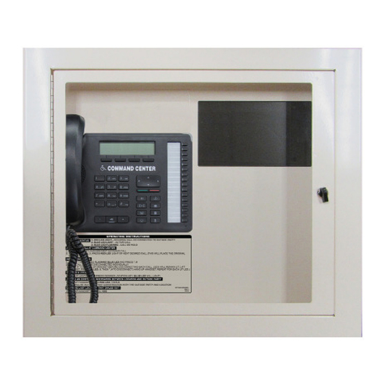
- Page 1 Installation & Operations Manual SmartView Command Center YEAR WARRANTY...
-
Page 2: Table Of Contents
Thank you for purchasing the SmartView Command Center System. Combining the brands of RATH Communications and JANUS Elevator Products, AVIRE Global is the largest Emergency Communication Manufacturer in North America and has been in business for over 35 years. We take great pride in our products, service, and support. Our Emergency Products are of the highest quality and our experienced customer support teams are available to remotely assist with site preparation, installation, and maintenance. -
Page 3: Pre-Installation Requirements
This manual only applies to the SmartView Command Center Master Station. Please see the SmartView 2 Installation and Operations manual for the SmartView 2 hardware requirements and installation steps. Pre-Installation Requirements Required (Not Included): • Elevator Emergency Phone • Minimum 22 or 24 AWG twisted, shielded cable •... - Page 4 SmartView Command Center: 1. Use the provided Allen Wrench to remove the back box or back plate from the cabinet. 2. Remove any applicable knockouts for cable routing or conduit. 3. Mount the back box or plate in location per owner’s specifications using appropriate mounting hardware. 4.
- Page 5 11. Using an Ethernet cable, plug the routed Internet connection from the building into the Ethernet port on the mini- PC. 12. On the side on the mini-PC, press and hold the red power button for 3 seconds. Both the mini-PC and the touch-screen display will power on after approximately 3 minutes.
-
Page 6: Distribution Module Wiring
Distribution Module Wiring The Distribution Module acts as a centralized wiring hub for the RATH by AVIRE SmartView Command Center system. It utilizes an interchangeable card system that allows for the Command Center phone, elevator emergency phones, and outside telephone line to land in one location. - Page 7 2004 Card 1 PHONE 4 Example 2002 PHONE 2 2001 PHONE 1 2003 PHONE 3 TELCO LINE 2 TELCO LINE 1 Note: Do not use the green and brown pairs COMMAND CENTER 2 COMMAND CENTER 1 2008 Card 2 PHONE 8 2006 Example PHONE 6...
- Page 8 NOTE: If using cellular, it is recommeded to use the RATH by AVIRE cellular gateway (2100-LTEVER4 or 2100-LTEGSM4). RATH by AVIRE cannot guarantee functionality of the system with third-party gateways.
- Page 9 Option 2: 56-116 Zone Systems • Each card installed will have six RJ45 connections • On top of each RJ45 card there is a label indicating the connection type: • S01-S_ is the port used for connecting elevator emergency phones •...
- Page 10 2020 Card 2 PHONE 20 Example 2018 PHONE 18 2017 PHONE 17 2019 PHONE 19 2024 PHONE 24 2022 PHONE 22 2021 PHONE 21 2023 PHONE 23 2028 PHONE 28 2026 PHONE 26 2025 PHONE 25 2027 PHONE 27 2032 PHONE 32 2030 PHONE 30...
- Page 11 3. Connect the elevator emergency phones to the Distribution Module: • Connect the twisted, shielded pair ran from the first elevator emergency phone to the to the (01-04) port on card 1 by connecting the shielded pair to the blue, blue-white pair on the RJ45 pigtail harness. •...
-
Page 12: Machine Room Phones
Machine Room Phones The RATH by AVIRE SmartView Command Center can have multiple “Machine Room” Phones connected to it. Machine Room Phones (RATH part # 2300-630RC) are used to call any of the connected phones from a location other than where the primary Command Center is located. -
Page 13: Command Center Operating Instructions
Program the system to call the call offsite without calling the Command Center first: 1. Press the speaker phone button 2. Dial 1, 3, 1 3. Dial 9, the external number, #, * to store the number 4. Verify the Command Center display shows “Forwarded On” followed by the phone number entered 5. -
Page 14: Smartview Setup
SmartView Setup Instructions Viewing the video feed from the elevators on the SmartView Command Center is done through the SmartView 2 monitoring website, smartviewhub.com. For security and privacy reasons, an account is required to log in to the SmartView Hub. It is recommended the building creates the account for the SmartView Command Center. - Page 15 4. In the search box, type in the SmartView ID number, then click the “Search” button. 5. In the search box, type in the SmartView ID number, then click the “Search” button. 6. In the Search Results, under the Building Manager role, click “Request Assign” button. 7.
- Page 16 8. Enter device description, Building Name, and Building Address if desired, then click “Assign” button. 9. Repeat steps 3-8 until all SmartView devices are added to the account. Installation and Operations Manual...
-
Page 17: Two-Way Visual Verification
Two-Way Visual Installation Verification 1. Once all SmartView 2 devices have been added to the building account, go to the touch-screen display on the SmartView Command Center, then double tap the “SmartView Hub” shortcut on the desktop. 2. Enter the username and password for the SmartView Command Center into the login box on the SmartView Hub, then click “Login to SmartView Hub”. - Page 18 3. On the camera page, find desired unit, then click the “Play” button next to it. 4. The camera feed will appear in the Live Preview window. 5. Type a test message in the text box labeled “Type to Communicate with Passengers”. 6.
-
Page 19: How It Works
How It Works An elevator passenger will press the emergency phone button in the elevator, prompting the elevator emergency phone to call out to the Command Center or directly to a monitoring service or an answering party. When the call is answered, a pre-recorded location message with the SmartView ID will be played (example: “Highland Hotel, Building A, Elevator 1, SmartView ID 123456”). - Page 20 If it is determined that rescue services are needed, you MUST send a message stating, “Help is on the way”. The monitoring or answering party must remain on the call and view the video feed until help has arrived. NOTE: After 10 minutes, a pop-up will appear asking to extend the session for another 10 minutes or close the window.
-
Page 21: Typical System Wiring
Typical System Wiring with SmartView 2 7200 Elevator Unit Machine Room CAT5 OR GREATER TO 2300-630RC BUILDING NETWORK (Optional MR Phone) OR 2100-SVCELLU 7100 RP7700104S (Power Supply UPS/Battery) Single Pair External Telephone Line CAT5 OR GREATER TO 7200 BUILDING NETWORK Single Single OR 2100-SVCELLU... - Page 22 Typical System Wiring with Elevator Emergency Phone Machine Room CAT5 OR GREATER TO 2300-630RC BUILDING NETWORK (Optional MR Phone) OR 2100-SVCELLU 7100 RP7700104S (Power Supply UPS/Battery) External Single Telephone Single Pair Line Pair 7200M Single CAT5 OR GREATER TO Pair BUILDING NETWORK OR 2100-SVCELLU Distribution...
-
Page 23: Troubleshooting
SmartView Master Station account. • If the device is already associated with another building account, follow the prompts on the site to request a device transfer, or contact the RATH by AVIRE customer service team at rath-janus@avire-global.com. Installation and Operations Manual... - Page 24 Problem Possible Cause & Solutions SmartView Hub will not • Unplug the Ethernet cable from the mini-PC and plug it into a laptop and verify load on the SmartView web browsing capabilities on the connection. Command Center • If the facility where the equipment is installed is using static IP addresses for Display: network connectivity, a static IP may need to be set up on the mini-PC in the SmartView Command Center.
-
Page 25: Simplified User Instructions
Simplified User Instructions Step 1 Log in to smartviewhub.com, if not already. Step 2 Click “Play” icon next to desired camera or type the SmartView ID into the search field. Step 3 In “Type to Communicate to Passenger” text box, type out message to car passenger. Passenger in car can then respond to message by using YES/NO buttons in the car. -
Page 26: Network Requirements
TCP / UDP Standard port for the Network Time Protocol (NPT). For detailed network security associated with the system or questions about the information mentioned above, please contact RATH by AVIRE at 1-800-451-1460 or emailing rath-janus@avire-global.com Installation and Operations Manual... -
Page 27: Registration Guide
9. Check the box next to “I’m not a robot” and complete the captcha. 10. Click “Submit” to finish registration. 11. Registration forms will be reviewed by the RATH by AVIRE customer service team and accounts will be created within 24 business operating hours. - Page 28 N56 W24720 N. Corporate Circle • Sussex, WI 53089 | 800-451-1460...
Need help?
Do you have a question about the RATH SmartView Command Center and is the answer not in the manual?
Questions and answers