Table of Contents
Advertisement
Quick Links
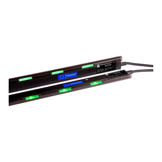
Panachrome+ with
Retrofit Smart 3D
Installation Guide
Ref No. Smart 3D 850GB Version 2
Product Description
Smart 3D combined with Panachrome+ 2D provides enhanced detection within the elevator environment specifically
aimed at 3D detection.
This new Panachrome+ G3851 controller allows for input from the Smart 3D Radar detector to enable an additional trigger
source for 3D detection. The smart Radar sensor is more sensitive to smaller objects, can distinguish cross-traffic and
moving targets and is not affected by clothing colors.
Items Required for Installation
In the box
+ Smart 3D Sensor and Housing
+ Smart 3D processor (adhesive tape attached)
+ Extension cable
+ 3 x M4 Spanner Head Screws
+ 3 x Pin Torqx Self-tapping Screws
+ 3 Smart 3D inserts (Black 65, Grey 67, and White 70)
+ Grommet for cable hole
Not included
+ Drill
+ 13mm/0.5" Drill bit
+ Screw driver
+ Panachrome+ (G3851) Controller
+ Panachrome+ Edges
Advertisement
Table of Contents

Related Manuals for AVIRE Panachrome+


Summary of Contents for AVIRE Panachrome+
- Page 1 Panachrome+ with Retrofit Smart 3D Installation Guide Ref No. Smart 3D 850GB Version 2 Product Description Smart 3D combined with Panachrome+ 2D provides enhanced detection within the elevator environment specifically aimed at 3D detection. This new Panachrome+ G3851 controller allows for input from the Smart 3D Radar detector to enable an additional trigger source for 3D detection.
- Page 2 Installation Check which insert is currently mounted in your Smart 3D. If the insert is correct proceed to step 3, if it needs replacing then follow the steps below Quick Summary Using a PH1 screw driver unscrew screws A and B located + Ensure the elevator has been marked clearly as out of either side of the sensor which hold the insert in place.
- Page 3 3.1.2 Side Opening Doors The Smart 3D sensor should be mounted approx. 300mm/11.81” away from the return jamb, on the header of the elevator car, with the flat face of the sensor pointing outwards from the elevator. Figure 7 Connect the extension cable to the connection wire on the Smart 3D sensor.
- Page 4 Configuration and Testing 5. Menu Navigation Panachrome settings can be changed by using the 4-button keypad and screen. Function Go back/cancel ▼ Menu and value down ▲ Menu and value up Menu item select and confirm To enter the settings menu first press ▼. Press ▼...
- Page 5 Smart 3D RADAR Settings The Smart 3D system is designed to change its field of view based on how close the doors are from shutting. The Smart 3D Radar recognises the doors going through three zones; High distance, Low Distance and Off distance. As the doors pass through each zone the detection zone is altered (made narrower and shorter) so that as the doors shut and the sensor is not triggered by the movement of the doors.
- Page 6 Some of the highlights of the 3D system are described below: + 3D Method 3D detection can be active for Smart 3D Radar or InfraRed (IR)(3D light curtains required), or both. + 3D Mode Irrespective of the active 3D detection system, IR and/or Smart 3D, both follow the selected 3D mode (3D light curtains needed for IR detection).
- Page 7 (2) this device must accept any interference received, including interference that may cause undesired operation. This device contains: FCC ID: G9B-305015 IC: 4680A-305015 CAUTION: Changes or modifications not expressly approved by Avire Ltd could void the user’s authority to operate the equipment. AVIRE Inc 415 Oser Avenue, Suite Q 631-864-3699 Hauppauge, NY 11788 631-864-2631 sales.us@avire-global.com...
Need help?
Do you have a question about the Panachrome+ and is the answer not in the manual?
Questions and answers