Table of Contents
Advertisement
Quick Links
Advertisement
Table of Contents

Related Manuals for SPETEC FMS Series


Summary of Contents for SPETEC FMS Series
- Page 1 TRANSLATED OPERATING MANUAL Cleanroom systems Retain for future use!
- Page 2 Cleanroom systems Cleanroom systems: Appliancestypes: FMS Series SuSi / FMS Basic / FBS Series SuSi / FBS-V Series SuSi / FBS Series Standard / EBS Series SuSi / EFBS Series SuSi / EFBS-V Series SuSi Cleanroom systems with acid-resistant fume cupboard:...
-
Page 3: Table Of Contents
Contents Contents ..............................3 List of figures ............................6 1 Introduction ............................8 Signs and symbols ........................8 1.1.1 Section-related warning notices ................. 9 1.1.2 Embedded warning notices ..................9 1.1.3 Other signs and symbols ..................10 1.1.4 Symbols used in the operating manual ..............10 List of abbreviations ....................... - Page 4 Required operating and maintenance areas............60 5.3.2 Requirements of the area of deployment ..............60 Mounting the Appliances ....................... 62 5.4.1 Requirements of the place of deployment ............... 62 5.4.2 Installing the FMS Series SuSi ................63 Page 4 of 108...
- Page 5 Contents 5.4.3 Installing the FMS-Basic ................... 66 5.4.4 FBS-V Series SuSi and EFBS-V Series SuSi installation ........68 Connecting power ........................69 5.5.1 Connecting the electricity supply ................69 6 Commissioning ..........................76 Safety measures before commissioning ................76 7 Operation ............................78 Safety measures in normal operation ..................
-
Page 6: List Of Figures
Figure 20: Mounting the FMS Series SuSi from the top ..............63 Figure 21: Mounting the FMS Series SuSi from the underside - 1 ..........64 Figure 22: Mounting the FMS Series SuSi from the underside - 2 ..........64 Figure 23: Installing laminar flow modules on the building ceiling .......... - Page 7 List of figures Figure 26: FBS-V Series SuSi and EFBS-V Series SuSi installation ..........68 Figure 27: Plug-in connections SuSi cleanroom system ............... 71 Figure 28: Basic cleanroom system plug connections ..............72 Figure 29: Standard module housing ....................73 Figure 30: Standard module housing ....................
-
Page 8: Introduction
Introduction This operating manual provides you with all the information you need for the seamless operation of the Cleanroom systems (hereafter also called the “Appliances”). The operating manual must be read, understood and applied by all persons tasked with the assembly / installation, transport, commissioning, operation, maintenance, cleaning, troubleshooting, decommissioning, dismantling and disposal of the Appliances. -
Page 9: Section-Related Warning Notices
1 Introduction 1.1 Signs and symbols 1.1.1 Section-related warning notices Section-related warning notices are not only relevant for a particular action, but apply to all actions within a section. Structure SIGNAL WORD Type and source of the danger! Potential consequence(s) of non-observance! ►... -
Page 10: Other Signs And Symbols
1 Introduction 1.1 Signs and symbols Danger levels DANGER WARNING CAUTION – NOTICE – (without warning triangle) 1.1.3 Other signs and symbols The info symbol indicates useful information. Texts following this label are lists. – ► Texts following this label describe measures in warning notices and action steps. Texts following this label describe activities to be carried out in the order given. - Page 11 1 Introduction 1.1 Signs and symbols Symbol Description Warning of danger of slipping This symbol warns of the danger of slipping on the ground. Fall warning This symbol warns of the danger of falling from work stations located at a higher level. There is a risk of falling from heights over 1 metre above the ground.
- Page 12 1 Introduction 1.1 Signs and symbols Symbol Description Disconnect mains plug before opening This symbol indicates that electrical equipment must be disconnected from the power supply before cleaning, maintenance or repair. Use safety goggles This symbol indicates that safety goggles must be worn in the area of deployment.
-
Page 13: List Of Abbreviations
European health, safety and environmental legislation. List of abbreviations Term Definition Exhaust Box Spetec EFBS Exhaust Flow Box Spetec Flow Box Spetec FBS-V Flow Box Spetec curtain Flow Module Spetec Protection Box Spetec Super Silent... -
Page 14: Warranty And Liability
– structural changes to the Cleanroom systems (conversions or other changes to the Appliances may not be made without the prior written consent of Spetec GmbH; in case of infringements the Cleanroom systems loses its suitability for use), –... -
Page 15: Copyright
The warranty provisions are contained in the General Terms and Conditions of the Spetec GmbH. Spetec GmbH offers a 24-month warranty on the appliances, with the exception of parts subject to wear such as the fan, main filter and pre-filter. -
Page 16: Safety
Safety WARNING Failure to observe the following safety instructions can have serious consequences: Danger to persons due to electrical, mechanical or chemical influences, failure of important Appliances functions and damage to the environment! ► Read through the safety and danger instructions in this section thoroughly before starting up the Cleanroom systems. - Page 17 2 Safety 2.1 Proper use In particular, to use defective or unsuitable accessories – is prohibited, – to operate the Cleanroom systems when its safety systems have been deactivated, tampered with or are faulty, – to operate the Cleanroom systems at times when untrained persons are present in the danger zone, –...
-
Page 18: Programming Changes To The Cleanroom Systems
Cleanroom systems. When using externally sourced parts, there is no guarantee that they have been designed and manufactured to withstand stresses and ensure safety. Parts and special equipment not supplied by Spetec GmbH are not approved for use on the Cleanroom systems. 2.1.3... -
Page 19: Reasonably Foreseeable Misuse
2 Safety 2.2 Personnel requirements 2.1.3.1 Reasonably foreseeable misuse ► Do not use the Cleanroom systems as a personal safety device. ► Keep persons who are unable or only partially able to assess potential hazards and who pose a danger to themselves and others (especially children) away from the cleanroom systems. -
Page 20: Instructed Personnel
2 Safety 2.2 Personnel requirements 2.2.2 Instructed personnel Instructed personnel have been trained in the tasks assigned to them and the potential dangers of improper behaviour through training provided by the operator or by qualified personnel. 2.2.3 Qualified personnel Qualified personnel are those who, because of their specialist training, knowledge, experience and understanding of the relevant regulations, are able to properly carry out the tasks assigned to them, recognising and avoiding any potential dangers independently. -
Page 21: Obligations Of The Personnel
2 Safety 2.2 Personnel requirements 2.2.6 Obligations of the personnel All persons who are engaged in work on the Cleanroom systems undertake, before commencing their work, – to observe the basic requirements of occupational safety and accident prevention, – to read the safety and warning signs in the operating manual and confirm with a signature that they have understood them. -
Page 22: Basic Safety Instructions
► If functionality is impaired, switch off the Cleanroom systems immediately. Have faults rectified by appropriately trained specialists or by Spetec GmbH. ► Keep the operating manual at the place where the Cleanroom systems is used at all times. -
Page 23: Special Danger Warnings/Residual Dangers
2 Safety 2.5 Special danger warnings/residual dangers Special danger warnings/residual dangers 2.5.1 Symbols used on the Appliances Place of Symbol Description attachment Warning signs Warning of falling objects For ceiling mounting on the housing This symbol warns of objects that could fall from above. -
Page 24: Danger From Electrical Energy
2 Safety 2.5 Special danger warnings/residual dangers Place of Symbol Description attachment Other symbols Disposal instructions Type plate This symbol indicates that the marked product must not be disposed of with household waste. CE marking Type plate The CE marking on the product is the manufacturer's declaration that the product meets the essential requirements of the relevant European health, safety and... - Page 25 2 Safety 2.5 Special danger warnings/residual dangers ► Before working on the electrical systems, isolate the Cleanroom systems from the current and secure them against being switched on again. ► Only allow work on the electrical equipment to be carried out by a competent and qualified electrician –...
-
Page 26: Dangers Due To Height-Adjustable Table
2 Safety 2.5 Special danger warnings/residual dangers 2.5.3 Dangers due to height-adjustable table WARNING The height-adjustable table poses a risk! A failure to observe this can lead to death or severe injury! ► Do not reach into the moving parts of the height-adjustable tables. ►... -
Page 27: Danger Due To Hot Surfaces
2 Safety 2.5 Special danger warnings/residual dangers 2.5.6 Danger due to hot surfaces WARNING Contact with hot components (motors) can cause burns! A failure to observe this can lead to severe injury! ► During all work near hot components, wear protective clothing and gloves. -
Page 28: Dangers From Lubricants And Cleaning Fluids
2 Safety 2.5 Special danger warnings/residual dangers 2.5.9 Dangers from Lubricants and cleaning fluids WARNING At the Cleanroom systems there are dangers from Lubricants and cleaning fluids! A failure to observe this can lead to severe injury! ► When handling, observe the safety regulations applicable to the product for Lubricants and cleaning fluids. -
Page 29: Dangers Due To Tripping
2 Safety 2.5 Special danger warnings/residual dangers 2.5.11 Dangers due to tripping CAUTION Tripping risk due to improperly laid energy supply cables! A failure to observe this can result in injuries! ► Always lay cables in the supply shaft in such a way as not to cause barriers or risk of tripping. -
Page 30: Danger Due To Use Of Incorrect Replacement Parts
Faulty or incorrect replacement parts can lead to damage, faults or total failure and can compromise safety! ► Only use original replacement parts. ► Acquire your replacement parts from Spetec GmbH. You can find the necessary information on replacement parts in the accompanying parts lists or in “1.6 Service/customer service”. -
Page 31: Personal Protective Equipment
2 Safety 2.6 Personal protective equipment Personal protective equipment When operating the Cleanroom systems, regardless of the workplace risk assessment, personal protective equipment is to be worn to minimize health hazards. The personal protective equipment must be designed in particular with regard to the corresponding risk. ►... -
Page 32: Safety And Protective Systems
2 Safety 2.7 Safety and protective systems Safety and protective systems ► Before switching on the Cleanroom systems, always check that all safety and protective systems are properly in place and functional. ► If partial components are supplied, the safety systems are to be applied by the operator according to regulations. -
Page 33: Responsibilities Of The Operator
2 Safety 2.9 Responsibilities of the operator Responsibilities of the operator The Cleanroom systems are used in industrial areas. The operator of the Cleanroom systems is thus subject to legal occupational safety obligations. Alongside the safety information given in this operating manual, the safety, accident prevention and environmental regulations valid at the place of deployment of the Cleanroom systems must be complied with. -
Page 34: Description Of Cleanroom Systems
All illustrations in this document are meant to provide a basic understanding and may differ from the actual design. Description of the Cleanroom systems Product series: – Laminar Flow Module – FMS Series SuSi – FMS Series Basic – Laminar flow boxes – FBS Series –... -
Page 35: Laminar Flow Module
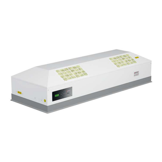
– FMS Series Basic The FMS Series is a filter module equipped with prefilters and a main filter of type H 14. FMS Series SuSi The FMS Series SuSi is a filter module with a display and can be converted into a laminar flow box. -
Page 36: Laminar Flow Boxes
FMS Series Basic The FMS Basic Series does not include a display and cannot be converted into a laminar flow box. Figure 2: FMS Series Basic – Standard module: Has a main switch and a potentiometer, which are built directly into the housing of the appliance. -
Page 37: Figure 3: Fbs Series
3 Description of Cleanroom systems 3.1 Description of the Cleanroom systems FBS Series The FBS Series is a tabletop appliance with sliding door and perforated shelf. Figure 3: FBS Series FBS Series Standard The FBS Series Standard is a tabletop appliance without sliding door and without perforated shelf. -
Page 38: Figure 5: Fbs-V Series
3 Description of Cleanroom systems 3.1 Description of the Cleanroom systems FBS-V Series The FBS-V Series is a laminar flow module with a cleanroom strip curtain. The curtain length is 2000 mm, but can be customised. Figure 5: FBS-V Series 3.1.2.2 Exhaust Flow Box The Exhaust Flow Box is available in the following variants:... -
Page 39: Figure 6: Efbs Series
3 Description of Cleanroom systems 3.1 Description of the Cleanroom systems EFBS Series The EFBS Series is a laminar flow box with an integrated acid-resistant suction device. Figure 6: EFBS Series EFBS-V Series The EFBS-V Series is a laminar flow box with an integrated acid-proof suction device and a cleanroom strip curtain. -
Page 40: Protection Box
3 Description of Cleanroom systems 3.1 Description of the Cleanroom systems 3.1.3 Protection Box PBS Series The Protection Box is a tabletop appliance. It does not have a filter attachment. It can be retrofitted at any time with a filter attachment to form a laminar flow box. The PBS Series is deployed as a cleanroom workstation and is used for the dust-proof storage of objects. -
Page 41: Exhaust (Protection) Box
3 Description of Cleanroom systems 3.1 Description of the Cleanroom systems 3.1.4 Exhaust (Protection) Box EBS Series The EBS Series is a bench-mounted fume cupboard with an integrated acid-proof extraction unit. Figure 9: EBS Series NOTICE ► Please note that no mechanical or activated charcoal filters are installed in the appliance. -
Page 42: Figure 10: Cleanboy Mini
3 Description of Cleanroom systems 3.1 Description of the Cleanroom systems CleanBoy Mini The CleanBoy Mini is a tabletop appliance. Figure 10: CleanBoy Mini CleanBoy Maxi The CleanBoy Maxi is a floor-standing appliance. Figure 11: CleanBoy Maxi Page... -
Page 43: Figure 12: Cleanboy Basic Mini
3 Description of Cleanroom systems 3.1 Description of the Cleanroom systems CleanBoy Basic Mini The CleanBoy Basic Mini is a table-top appliance and is equipped with a laminar flow module from the Basic series. Figure 12: CleanBoy Basic Mini CleanBoy Basic Maxi The CleanBoy Basic Maxi is a floor-standing appliance and is equipped with a laminar flow module from the Basic series. -
Page 44: Type Plate
3 Description of Cleanroom systems 3.2 Safety systems 3.1.6 Type plate A type plate is attached to each product group to record the key data in accordance with the Machinery Directive 2006/42/EC. If a cleanroom system consists of several parts, a unit number (Unit No.) and a type plate are affixed to each. -
Page 45: Operating Modes
Automatic operation can endanger the operator if the Cleanroom systems are used improperly. ► Check that all enclosures are fitted in this operating mode. Technical data 3.4.1 Cleanroom systems – FMS Series SuSi – FMS Basic – FBS Series SuSi – FBS-V Series SuSi –... - Page 46 3 Description of Cleanroom systems 3.4 Technical data 3.4.1.1 Cleanroom systems with acid-resistant fume cupboard – EFBS Series SuSi – EFBS-V Series SuSi – EBS Series SuSi Performance data of the acid-resistant extraction unit Voltage supply 230 V AC Frequency 50 / 60 Hz Power consumption 20 W...
-
Page 47: Power Consumption
3 Description of Cleanroom systems 3.4 Technical data 3.4.2 Power consumption 3.4.2.1 Laminar Flow Module FMS Series SuSi Maximum power Average power Identifier consumption consumption at 0.4 m/s in W in W Laminar flow module FMS 37 Laminar flow module FMS 56... -
Page 48: Filter Dimensions
3 Description of Cleanroom systems 3.4 Technical data 3.4.3 Filter dimensions 3.4.3.1 Laminar Flow Module FMS Series SuSi Filter dimensions in Identifier Weight in kg Laminar flow module FMS 24 * 610 x 400 Laminar flow module FMS 37 610 x 610... - Page 49 3 Description of Cleanroom systems 3.4 Technical data EFBS Series SuSi Filter dimensions in Identifier Weight in kg Laminar Flow Box EFBS 37 610 x 610 Laminar Flow Box EFBS 56 915 x 610 Laminar Flow Box EFBS 75 1220 x 610 Laminar Flow Box EFBS 93 1525 x 610 Laminar Flow Box EFBS 112...
-
Page 50: Dimensions
1220 x 610 3.4.4 Dimensions 3.4.4.1 Dimensions FMS Series SuSi Ceiling section) Ceiling section) Filter) Figure 15: Dimensions FMS Series SuSi Identifier V in mm W in mm X in mm Y in mm Z in mm Laminar flow module FMS 37... -
Page 51: Figure 16: Dimensions Fms Series Basic
Laminar flow 1600 1620 1560 1525 1495 module FMS 93 Laminar flow 1905 1925 1865 1830 1800 module FMS 112 3.4.4.2 Dimensions FMS Series Basic (ceiling section) (filter) Thread (ceiling suspension position optionally available) Figure 16: Dimensions FMS Series Basic Page... -
Page 52: Figure 17: Dimensions Fbs Series Standard
3 Description of Cleanroom systems 3.4 Technical data 3.4.4.3 Dimensions FBS Series Standard Figure 17: Dimensions FBS Series Standard Identifier X in mm Y in mm Laminar Flow Box FBS 37 Standard Laminar Flow Box FBS 56 Standard Laminar Flow Box FBS 75 Standard 1255 1220 Laminar Flow Box FBS 93 Standard... -
Page 53: Airborne Noise Emissions
3 Description of Cleanroom systems 3.4 Technical data Identifier X in mm Y in mm FBS / EFBS / PBS / EBS Series 37 FBS / EFBS / PBS / EBS Series 56 1040 FBS / EFBS / PBS / EBS Series 75 1255 1345 FBS / EFBS / PBS / EBS Series 93... -
Page 54: Transport And Storage
Delivery by an authorised transport company The Appliances will be delivered to the customer by a transport company authorized by Spetec GmbH. ► If the location of the Appliances is changed, please ask Spetec GmbH for information regarding transport. Inspections when handed over to recipient The Cleanroom systems must be investigated for visible transport damage upon arrival at the customer’s base of operations. -
Page 55: Unpacking
► Make sure to keep the accompanying documents; they contain important information on handling the Cleanroom systems. ► Check the contents of the package for visible transport damage. ► If you detect transport damage or discrepancies between the contents and your order, inform Spetec GmbH. 4.3.2 Repackaging See chapter “4.3.1 Unpacking”. -
Page 56: Reliable Transport Aids
4 Transport and storage 4.5 Reliable transport aids ► Always have an additional person secure the transport route. ► Ensure that transport routes and areas under suspended loads always remain clear of persons. ► Do not use any supply lines or mounted parts as attachment points. Lifting lugs on components (if present) are intended only for lifting the individual components, not for lifting the entire assembly. -
Page 57: Intermediate Storage
4 Transport and storage 4.7 Intermediate storage Intermediate storage If the Cleanroom systems is not immediately set up after delivery, it must be stored carefully in a protected location. The Cleanroom systems must be stored so that it is protected from cold, damp, dirt, chemical and mechanical influences. Please find the recommended storage conditions for the Cleanroom systems in the chapter “Ambient conditions”. -
Page 58: Assembly
Assembly Check the Cleanroom systems for damages before installation. If there is visible damage, the Cleanroom systems must not be installed and the manufacturer must be contacted. Information on dangers during assembly DANGER Risk of electrocution! Failure to observe this will lead to death or severe injury! ►... -
Page 59: Preparatory Measures
– connections for the power supply have been prepared. – a suitable lifting device is used for the laminar flow module. ► Please note that Spetec handles can be purchased for better handling during assembly. Choice of deployment location WARNING... -
Page 60: Required Operating And Maintenance Areas
5 Assembly 5.3 Choice of deployment location 5.3.1 Required operating and maintenance areas ► When selecting the place of deployment, take into account the ambient conditions. ► When selecting the place of deployment, take into account the need for operational and maintenance areas. ►... - Page 61 5 Assembly 5.3 Choice of deployment location WARNING Danger of injury due to lack of space! A risk of serious injuries such as scratches, stabbing or broken bones arises where work equipment and/or components are arranged too closely together! ► Select the place of deployment of the Cleanroom systems in such a way that the personnel has the necessary room to move around the operating area without hindrance or restriction.
-
Page 62: Mounting The Appliances
5 Assembly 5.4 Mounting the Appliances Mounting the Appliances 5.4.1 Requirements of the place of deployment The following requirements must be met at the place of deployment: ► Ensure that the place of deployment has sufficient load-bearing capacity and is level. ►... -
Page 63: Installing The Fms Series Susi
Place the FMS Series SuSi flush on the profile frame. Refer to the technical data for the internal dimensions of the profile frame. Bolt the FMS Series SuSi to the profiled frame using M6 raised-countersunk bolts. Check the FMS Series SuSi for a tight fit. -
Page 64: Figure 21: Mounting The Fms Series Susi From The Underside - 1
Mounting the FMS Series SuSi from the underside Mounting a laminar flow module from the underside enables the main filter to be changed from below. Figure 21: Mounting the FMS Series SuSi from the underside - 1 Bolts Suspension (not included in the scope of delivery) -
Page 65: Figure 23: Installing Laminar Flow Modules On The Building Ceiling
5 Assembly 5.4 Mounting the Appliances Slide the FMS Series SuSi through the profile frame from below. Refer to the technical data for the internal dimensions of the profile frame. Attach the FMS Series SuSi with a suspension bracket. Bolt the FMS Series SuSi to the profile frame. -
Page 66: Installing The Fms-Basic
5 Assembly 5.4 Mounting the Appliances 5.4.3 Installing the FMS-Basic WARNING Risk of injury due to the main filter falling out! Failure to observe this can lead to death or severe injury! ► Only undo the locking plates during installation and maintenance. ►... -
Page 67: Figure 25: Mounting On A Support Frame - 2
Loosen the countersunk bolts (2) with a 2.5 mm Allen key or Torx Tx20. Remove the locking plates (1). Place the FMS Series Basic flush on the support frame. Bolt the FMS Series Basic to the support frame using M6 bolts. Check the FMS Series Basic for tight fit. Page... -
Page 68: Fbs-V Series Susi And Efbs-V Series Susi Installation
Cleanroom strip curtain Washer Cap nut Install the FMS Series SuSi on the building ceiling. Attach the cleanroom strip curtain according to the markings on the front and back by sliding the holes of the cleanroom strip curtain onto the threaded rods. -
Page 69: Connecting Power
5 Assembly 5.5 Connecting power Connecting power 5.5.1 Connecting the electricity supply IEC plug The supplied IEC plug is used to provide a power supply and is pluggedinto the “power” socket. Control cables The 7-pin control cable (remote) is used to connect several modules (primary / secondary) and to connect a cable remote control. - Page 70 / or personal injury resulting from incorrect installation of the Cleanroom systems. ► Please note that there is no fixed sequence for connecting the cables. However, Spetec recommends connecting the control cables first and then the IEC plug for the 230 V power supply.
-
Page 71: Plug Connections
5 Assembly 5.5 Connecting power 5.5.1.1 Plug connections Plug-in connections SuSi cleanroom system Figure 27: Plug-in connections SuSi cleanroom system 7-pin plug / connection exclusively to the secondary or cable remote control Light output (3-pin) Mains output (3-pin) Power supply Device fuse PLC connection (12-pin)* NOTICE... -
Page 72: Figure 28: Basic Cleanroom System Plug Connections
5 Assembly 5.5 Connecting power *PLC connection can be optionally installed at the time of purchase. Please refer to the additional instructions. The PLC connection is located in the cable remote control on a primary device. SuSi plug types There are three different plug types with four different functions: –... -
Page 73: Figure 29: Standard Module Housing
5 Assembly 5.5 Connecting power 5.5.1.2 SuSi cleanroom system versions There are three versions of the SuSi device: – Standard module: The operating terminal is installed in landscape format in the housing of the appliance. – Primary Module: Does not have an operating terminal in the housing, but an external cable remote control and control cable (5 m). -
Page 74: Figure 31: Standard Module Housing
5 Assembly 5.5 Connecting power Secondary module: operating terminal via cable remote control. The cover plate has a closed hole (white plug). Figure 31: Standard module housing 5.5.1.3 Connection options for the SuSi cleanroom system Up to 50 modules can be connected. Only one standard module or one primary module may be present in the entire system;... -
Page 75: Figure 33: Connection Option 2 Cleanroom System Susi
5 Assembly 5.5 Connecting power Connection option 2: – 1x primary module and up to 50x secondary modules FMS Secondary 2 FMS Primary 1 FMS Secondary 1 The wired remote control The plugs can be can be connected to any connected in any order, available slot in the system. -
Page 76: Commissioning
Commissioning Safety measures before commissioning WARNING Danger of injury due to lack of space! A risk of injuries such as scratches, puncture wounds or broken bones exists if work equipment and/or components are arranged too closely together! ► Select the place of deployment of the Cleanroom systems in such a way that the personnel has the necessary room to move around without hindrance or restriction in the operation area. - Page 77 6 Commissioning 6.1 Safety measures before commissioning ► Carry out the following activities before initial commissioning or subsequent repeat commissioning: ► Check and ensure that all safety systems have been attached and are functioning. ► Check the Cleanroom systems for visible damage; rectify any defects immediately or report them to the supervisory staff - the Cleanroom systems may only be operated when in perfect condition.
-
Page 78: Operation
Operation Safety measures in normal operation DANGER Risk of electrocution! Failure to observe this will lead to death or severe injury! ► Do not touch any live parts! ► Do not attach any grounding to mechanical connecting elements. ► Observe the safety instructions in chapter “2 Safety”. ►... -
Page 79: Susi Cleanroom Systems
7 Operation 7.2 SuSi Cleanroom systems SuSi Cleanroom systems NOTICE ► Contact customer service if the display shows “call service”. Display Figure 34: LCD display, four lines Type designation Speed level Flow velocity display in m/sec Operating hours display / call service Page... - Page 80 7 Operation 7.2 SuSi Cleanroom systems Settings Function Explanation Increase flow Flow speed can be adjusted in stages. velocity – The display shows: eco, 0.25 m/s, 0.30 m/s, 0.35 m/s, 0.40 m/s; 0.45 m/s, 0.50 m/s, max. speed: 0.50 m/s. Reduce flow Flow speed can be adjusted in stages.
-
Page 81: Basic Cleanroom Systems
7 Operation 7.3 Basic cleanroom systems Basic cleanroom systems Control elements Figure 35: Basic 1 controls Mains on / off switch Figure 36: Basic 2 controls Setting the flow velocity Function Explanation Mains on / off switch Switching the fan on / off Setting the flow velocity Ungraduated regulation of the flow rate Page... -
Page 82: Cleanroom Systems From The Efbs, Efbs-V And Ebs Series
7 Operation 7.4 Cleanroom systems from the EFBS, EFBS-V and EBS Series Cleanroom systems from the EFBS, EFBS-V and EBS Series Control elements Figure 37: Operating elements EFBS, EFBS-V and EBS Series Mains on / off switch Setting the suction power Function Explanation Mains on / off switch... -
Page 83: Eliminate Faults/Errors
Eliminate faults/errors WARNING Hazards are posed by the Appliances during troubleshooting! Failure to observe the instructions may result in damage, malfunctions, or total failure of the Cleanroom systems as well as impairment of the safety of Cleanroom systems. ► Disconnect the Cleanroom systems from all power sources before troubleshooting. - Page 84 8 Eliminate faults/errors 8.1 Errors and corrective measures Error/Fault Cause Corrective measure Mains voltage not provided Check mains voltage Check fuse and replace if Device cannot be Fuses defective necessary switched on Repair by the Error in the electronics manufacturer Individual laminar flow Check fuse and replace if modules cannot be...
-
Page 85: Maintenance And Cleaning
Maintenance and cleaning Safety measures during maintenance DANGER Danger to life due to residual voltage in the fan motors caused by capacitors! Touching the fan motors can lead to death or serious injury! ► Do not touch any metal parts. ►... -
Page 86: Inspection And Maintenance Work
Complete cleanroom system connections Complete cleanroom system Visual inspection of bolt connections 9.2.5.2 Annually Complete cleanroom system Check bolt connections 9.2.6.1 Filters Check, replace if necessary 9.2.6.2 Special maintenance intervals Electrical equipment Safety check 9.2.7.1 Complete cleanroom system Spetec Service 9.2.7.2 Page... -
Page 87: Preparatory Electrical Measures
9 Maintenance and cleaning 9.2 Inspection and maintenance work 9.2.2 Preparatory electrical measures DANGER Risk of fatal injury due to electrocution! Live parts can lead to electrocution or severe injury when touched. ► Only allow work on the electrical equipment to be carried out by a qualified electrician who is specially trained for work on electrical equipment and who can recognise and avoid dangers. - Page 88 9 Maintenance and cleaning 9.2 Inspection and maintenance work 9.2.3.2 Cleaning NOTICE ► Never clean the acrylic glass panes and strip curtains with household cloths, as these will scratch the surface. Regular maintenance and observance of a few basic requirements will ensure trouble- free operation and a long service life.
- Page 89 9 Maintenance and cleaning 9.2 Inspection and maintenance work – Utilisation: Cleaning and disinfection, especially for acrylic glass, aluminium composite panels and TPE. In the case of aluminium sheet and anodised aluminium, the exposure time should be kept short and the surfaces thoroughly wiped.
-
Page 90: Maintenance - Weekly
9 Maintenance and cleaning 9.2 Inspection and maintenance work Maintenance – weekly 9.2.4 9.2.4.1 Cleaning NOTICE ► Never clean the acrylic glass panes and strip curtains with household cloths, as these will scratch the surface. Regular maintenance and observance of a few basic requirements will ensure trouble- free operation and a long service life. -
Page 91: Filter Change
9 Maintenance and cleaning 9.2 Inspection and maintenance work 9.2.6.2 Filter change WARNING Risk of injury due to voltage in the cleanroom system! Failure to observe this can lead to death or severe injury! ► Disconnect the mains plug of the cleanroom system before opening it. WARNING Risk of injury from falling components! Failure to observe this can lead to death or severe injury! -
Page 92: Figure 38: Changing The Pre-Filter
9 Maintenance and cleaning 9.2 Inspection and maintenance work Changing the pre-filter Figure 38: Changing the pre-filter Bolts (6 pieces) Pre-filter with filter grille Filter grille Pre-filter Remove the bolts. Remove the pre-filter with the filter grille. Slide the pre-filter out of the filter grille. Insert the new pre-filter into the filter grille. -
Page 93: Figure 39: Changing The Main Filter For Freestanding Appliances
9 Maintenance and cleaning 9.2 Inspection and maintenance work Changing the main filter for freestanding appliances NOTICE ► Do not change the main filter from below on floor-standing appliances. To carry out this operation, lift the laminar flow module upwards. ►... -
Page 94: Figure 40: Changing The Main Filter For Cleanroom Cells / Suspended Laminar Flow Modules
9 Maintenance and cleaning 9.2 Inspection and maintenance work Changing the main filter for clean room cells and suspended laminar flow modules WARNING Risk of injury due to the main filter falling out! Failure to observe this can lead to death or severe injury! ►... - Page 95 9 Maintenance and cleaning 9.2 Inspection and maintenance work Bolt in the changing device until the red mark is no longer visible. Check that the changing device for a tight fit. Loosen the remaining countersunk bolts. Figure 41: Changing the main filter in cleanroom cells / suspended laminar flow modules - Changing device Undo the wing bolts of the changing device alternately in steps of approx.
-
Page 96: Special Maintenance Intervals
9 Maintenance and cleaning 9.2 Inspection and maintenance work Figure 42: Changing the main filter for cleanroom cells / suspended laminar flow modules Main filter Install the main filter in reverse order. Check the main filter for tight fit. The laminar flow module can be put back into operation. After relaunch, a filter leak test in accordance with DIN 14644 is recommended. -
Page 97: Servicing Third-Party Components
Mechanical inspection and repair if necessary – Certification with confirmation of the cleanroom class – Indication of the measured particle count inside and outside the Spetec cleanroom system 9.2.8 Servicing third-party components Further information on servicing work on third-party components can be found in the supplier documentation. -
Page 98: Decommissioning And Disassembly
► Before disassembling, switch off the Cleanroom systems. ► Always wear the protective equipment required for the work in question (e.g. protective clothing, safety shoes, protective gloves and safety helmet). ► If in doubt, consult Spetec GmbH. 10.1 Decommissioning 10.1.1 Decommissioning the electrical systems Switch off the Cleanroom systems. -
Page 99: Disassembly
10 Decommissioning and disassembly 10.2 Disassembly DANGER Risk of fatal injury due to unintentional restart and electric shock! Unintentional restart and electric shock can lead to severe injury or death! ► Only have the decommissioning work carried out by authorised and qualified specialist personnel. -
Page 100: Disassembly At Great Heights
10 Decommissioning and disassembly 10.3 Disposal 10.2.1 Disassembly at great heights WARNING Risk of injury due to falling from a great height! Failure to observe this will lead to death or severe injury! ► Only allow instructed and authorised personnel to carry out work at great heights. -
Page 101: Disposal Of Auxiliary And Operating Materials
► Ensure that auxiliary and operating materials do not get into the groundwater, bodies of water or the sewage system. ► Dispose of auxiliary and operating materials in accordance with the applicable regulations or, if necessary, contact Spetec GmbH. Page... -
Page 102: Appendix
Appendix 11.1 EC Conformity Declaration On the following pages you will find the EC Conformity Declaration for these Appliances and the appended documents. Page... - Page 103 11 Appendix 11.1 EC Conformity Declaration EC Conformity Declaration (translated conformity declaration) Manufacturer / authorized Spetec GmbH representative: Am Kletthamer Feld 15 85435 Erding Person authorized to compile the Spetec GmbH technical documents: Am Kletthamer Feld 15 85435 Erding Product:...
-
Page 104: Spare Parts List
11 Appendix 11.2 Spare parts list 11.2 Spare parts list Identifier Item No. Microfuse T 1.60 A 40-0040 acid fume cupboard Microfuse T 3.15 A 40-0070 (size 24 to 112) Device supply line 42-0025 Centrifugal fan 22-0203 Front assembly incl. display 06-0053 Front assembly Primary 06-0051... -
Page 105: Maintenance Manual
11 Appendix 11.3 Maintenance manual 11.3 Maintenance manual Device / room: _____________________________________________________________________ Serial number: ____________________________________________________________________ 1. Maintenance interval □ YES □ NO Visual inspection □ YES □ NO Functional inspection □ YES □ NO Pre-filter change □ YES □ NO Main filter change □... - Page 106 11 Appendix 11.3 Maintenance manual 3. Maintenance interval □ YES □ NO Visual inspection □ YES □ NO Functional inspection □ YES □ NO Pre-filter change □ YES □ NO Main filter change □ YES □ NO Particle measurement □ YES □...
-
Page 107: Appended Documents
11 Appendix 11.4 Appended documents 11.4 Appended documents The following documents are appended to this operating manual: 11.4.1 Manufacturer documentation of the purchased components The appendices to the operating manual consist of the following documents: – Manufacturer documentation of the purchased components Page... - Page 108 ® Spetec GmbH Am Kletthamer Feld 15 85435 Erding Telephone: +49 8122/95909-0 Fax: +49 8122/95909-55 Email: spetec@spetec.de Internet: www.spetec.de...
Need help?
Do you have a question about the FMS Series and is the answer not in the manual?
Questions and answers