
Related Manuals for Daewoo DV-K580NZ-T


Summary of Contents for Daewoo DV-K580NZ-T
- Page 1 S/M No. : VK580NTEF0 Service Manual TIME LAPSE VCR Model: DV-K580NZ-T DAEWOO ELECTRONICS CO., LTD. http : //svc.dwe.co.kr Jan. 2000...
-
Page 2: Table Of Contents
TABLE OF CONTENTS SAFETY&PRECAUTIONS ... 2 EXTERNAL VIEWS ... 4 FRONT VIEWS FUNCTION ...4 REAR VIEWS FUNCTION ...5 ELECTRICAL ADJUSTMENT ... 6 SPECIFICATIONS ... 14 TIMELAPSE REC/PB SPEED CHART ... 15 CIRCUIT OPERATION ... 16 TROUBLE SHOOTING FLOW CHART ... 24 POWER CIRCUIT ...24 SERVO-SYSCON CIRCUIT ...26 VIDEO CIRCUIT ...34... -
Page 3: Safety&Precautions
SAFETY&PRECAUTIONS SAFETY CHECK AFTER SERVING Examine the area surrounding the repaired location for damage or deterioration. Observe that screw, parts and wires have been returned to original positions. Afterwards, perform the following tests and conform the specified values in order to verify compliance whit safety standards. - Page 4 4. Leakage current test Confirm specified or lower leakage current between B(earth ground, power cord plug prongs) and externally exposed accessi- ble parts (RF terminals, antenna terminals, video and audio input output terminals, microphone jacks, earphone jacks, etc.) Measuring method:(Power ON) Insert load Z between B(earth ground, power cord plug prongs) and exposed accessible parts.
-
Page 5: External Views
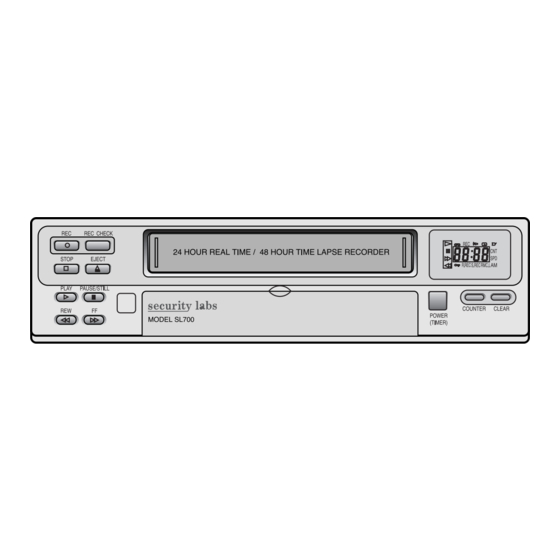
EXTERNAL VIEWS 1. FRONT VIEWS FUNCTION 1) STOP button 2) REC button 3) REC CHECK button 4) EJECT button 5) CASSETTE LOADING DOOR 6) DISPLAY PANEL 7) PLAY button 8) REW button 9) FF button 10) PAUSE/STILL button 11) REMOTE SENSOR 12) REMOCON LOCK SWITCH 13)SET LOCK SWITCH 14)RESET button... -
Page 6: Rear Views Function
2. REAR VIEWS FUNCTION 1) AC POWER CORD 2) WARNING OUT terminal 3) SERIES IN terminal 4) COM terminal 5) SERIES OUT terminal 6) SW OUT terminal 7) VIDEO OUT jack 8) VIDEO IN jack 9) AUDIO IN jack 10)TAPE END terminal 11) PANIC IN terminal 12)COM terminal 13)ALARM OUT terminal... -
Page 7: Electrical Adjustment
ELECTRICAL ADJUSTMENT 1. SERVO/SYSCON CIRCUIT ADJUSTMENT METHOD v VIDEO HEAD SWITCHING POSITION Adjustment Part Checking Point R595 PT501 PIN3 v CONNECTION METHOD TJ396 PT501 v ADJUSTMENT PROCEDURE 1) Play back the test tape. 2) Set the oscilloscope in the chop mode connect the CH1 to SW pulse(PT501 (r)PIN), the CH2 to TJ396(video out) with CH1 triggering. -
Page 8: Video Circuit Adjustment Method
TJ396 v ADJUSTMENT PROCEDURE 1) Supply the Color Bar Signal to the VIDEO IN JACK, and set the VCR to the STOP mode. 2) Connect the oscilloscope to TJ396 and trigger the scope with a composite sync signal at TJ302. - Page 9 ELECTRICAL ADJUSTMENT (2) PLAYBACK Y-SIGNAL OUTPUT LEVEL Adjustment Parts Checking Point R396 v CONNECTION METHOD TJ396 TJ302 PB-Y R396 v ADJUSTMENT PROCEDURE 1) Playback the COLOR BAR Test tape (DN-1). 2) Connect the oscilloscope to TJ396 and trigger the scope with a composite sync signal at TJ302. ±...
- Page 10 VIDEO IN is shorted with Ground v ADJUSTMENT PROCEDURE 1) Set the VCR to STOP mode without Video Signal.(VIDEO IN JACK is shorted with Ground) 2) Connect the frequency counter TJ391. 3) After Inserting Rec Tape REC in SP Mode ±...
- Page 11 FM DEV v ADJUSTMENT PROCEDURE 1) Supply the Color Bar Signal to the VIDEO IN JACK, and set the VCR to the REC mode. 2) Connect the oscilloscope to TJ396 and trigger scope with a composite sync signal at TJ302.
- Page 12 TJ302 v ADJUSTMENT PROCEDURE 1) Supply the Color Bar Signal to the VIDEO IN JACK, and set the VCR to the REC mode. 2) Connect the oscilloscope to TJ491 and trigger the scope with a composite sync signal at TJ302.
- Page 13 ELECTRICAL ADJUSTMENT (6) Y RECORD CURRENT Adjustment Parts Checking Point R491 v CONNECTION METHOD REC-Y TJ302 v ADJUSTMENT PROCEDURE 1) Supply the Color Bar Signal to the VIDEO IN JACK. 2) After Inserting a Rec Tape, Rec in SP MODE. 3) Connect the oscilloscope to TJ491 and trigger the scope with a compos- ite sync signal at TJ302.
-
Page 14: Audio Circuit Adjustment Method
ELECTRICAL ADJUSTMENT 3. AUDIO CIRCUIT ADJUSTMENT METHOD (1) AUDIO RECORD BIAS Adjustment Parts Checking Point Measuring Equipment Condition of Adj. Test Tape R292 Audio Level Meter REC mode Blank Tape v CONNECTION METHOD R292 REC BIAS Audio Level Meter v ADJUSTMENT PROCEDURE 1) Supply the signal in the OPEN mode. -
Page 15: Specifications
SPECIFICATIONS Video Signal system REC/PB System Tape Width Record system of Luminance Signal Record system of Color Signal Tape Speed (T-120) Record/Play Time (T-120) FF/REW Time (T-120) Video Signal Input Video Signal Output Luminance Signal to Noise ratio Horizontal resolution Audio Signal Input Audio Signal Output Audio Signal to Noise Ratio (A.Weighted) -
Page 16: Timelapse Rec/Pb Speed Chart
TIMELAPSE REC/PB SPEED CHART TAPE MODE T-120 REC MODE T-160 T-120 PLAY MODE T-160 AUDIO TAPE SPEED 2.7H 2.7H POSSIBLE REMARK 49.5H EP 24H MODE IS POSSIBLE IN PLAY MODE. 49.5H NOT POSSIBLE... -
Page 17: Circuit Operation
CIRCUIT OPERATION 1. VIDEO PART 1-1) EE MODE Video Signal which is output from RL902 is input to pin 37 of IC301 through OSD IC. It is amplified 6dB by AGC, then it is output to pin 34. This output signal is output to Video Jack through RL902 of RELAY IC. 1-2) REC MODE The signal which is input to pin 37 of IC301 is output to pin 3 through IC internal AGC AMP. - Page 18 1-3) PB MODE When playing the tape, the signal which is picked up from the tape is amplified 50 dB. Then luminance signal goes to pin 11 and color signal goes to pin 7 through AGC. Luminance signal of pin 11 is input to pin 39 of IC301 through PB EQ cir- cuit in order to match playback characteristic.
-
Page 19: Audio Part
CIRCUIT OPERATION 2. AUDIO PART 2-1) EE MODE External AUDIO signal which is input to pin 16 of IC201 is output from pin 22 of IC201 after being amplified through ALC and Line Amp. 2-2) REC MODE It will be the REC mode when REC 5V is input to pin 24 of IC201. Input signal will be replaced on the tape through R/P HEAD after being amplified and modulated with Bias Frequency. - Page 20 3. SERVO SYSCON PART 3-1) BLOCK DIAGRAM DRUM PG FG AMP Start end SENSOR & REEL SENSOR VIDEO BLOCK <K580N-T SERVO SYSCON BLOCK> CAPSTAN SPEED CTL IC501 M37775M5H u-COM PROCESSOR BACK OSC& UP BATT RESET AUDIO BLOCK CIRCUIT OPERATION LOADING CAM DRIVE TERMINAL BLOCK...
- Page 21 CIRCUIT OPERATION 3-2) TIME LAPSE RECORDING METHOD The numbers of VHS 2HOUR (SP), 6HOUR (EP) REC FIELD are 60 field/sec, then it will be 1FRAME = 33.3Ms, 1FIELD = 16.65Ms. CAPSTAN MOTOR FG numbers for Time Lapse are 6HOUR(EP) = 720 numbers/sec, 2HOUR(SP) = 720*3=2160 num- bers/sec.
-
Page 22: Alarm Input
Connect DOOR SW&SENSOR etc and this port will be used for emergency recording by using open/close status. N/O(NORMALY OPEN) N/C(NORMALY CLOSED) ALARM OUTPUT This port is always triggered during ALARM REC, which is used to inform the outside that time lapse VCR is now perform- ing Alarm Recording. Minimum 2mins. HIGH u Trigger Time will be the set time on MENU, it will be approximately 2 minutes at least. - Page 23 CIRCUIT OPERATION TAPE END OUT When the recording tape ends during recording, end sensor will be detected. This port is used Alarm to outsider until release the end sensor detecting. SW OUTPUT This port is used triggering video signal with external equipment during recording. VIDEO SIGNAL 1FIELD...
- Page 24 When the series recording proceeds after setting the series recording to “ on” , this port is used to receive the control signal to the set which will be recorded continuously after pre-recording set. WARNING OUTPUT This port is used to inform emergency status of Time Lapse VCR Set to outsider. 200ms EMER...
-
Page 25: Trouble Shooting Flow Chart
TROUBLE SHOOTING FLOW CHART 1. POWER CIRCUIT When changing the parts which are broken first, remove the power plug from the socket and then discharge the voltage across the terminals of C806. (Use an external K When check the primary circuit , use the oscilloscope isolated properly (Use the isolated transformer) and connect GND to the primary GND, however it is not necessary to isolate the oscilloscope when check the secondary circuit. - Page 26 TROUBLESHOOTING FLOW CHART B. CHECKING THE SECONDARY CIRCUIT Check each output voltage Check M801. Check any diode which causes no power Check any COIL, or capacitor which causes no power...
-
Page 27: Servo-Syscon Circuit
TROUBLESHOOTING FLOW CHART 2. SERVO-SYSCON CIRCUIT Playback picture is not good Noise appears although adjusting tracking. Is CTL pulse output at pin 25 of IC501? The voltage of pin 89 of IC501 not changing? Playback picture Check IC501 is not good Adjust tracking. - Page 28 Playback picture is not good. Noise appears on the screen on the whole. Is SW-pulse applied to video IC? Is Enve. waveform supplied to pin 4 of P T501? Check video circuit. Noise appears on the screen at the bottom Is sw pulse supplied from pin 18 of IC501? Check connector,...
- Page 29 TROUBLESHOOTING FLOW CHART Auto-stop during playback. Is reel pulse applied to pin 5 and 6 of IC501? Is D. FG applied to pin 24 of IC501? Check IC501. Check reel sensor. Check connector and D. FG circuits.
- Page 30 Drum M/T loading stops. Is motor 12V supplied from Ic504 pin7, 8? Is 5.2V supplied from POWER CIRCUIT? Check connector and motor. TROUBLESHOOTING FLOW CHART Check circuit adjacent EVER +12.4V. Check power module. Check D814.
- Page 31 TROUBLESHOOTING FLOW CHART Capstan M/T loading stops. Is motor 12V supplied? Is the input of pin 6 of P501 2.5V~3.5V? Is pin 4 of P501 2.5V? Does pin 3 of IC501 supply C.PWM? Check connector and motor. Check power Module. Check circuit of R516, R517, R520, C509, C511.
- Page 32 Drum M/T and capstan M/T rotate at regular speed. (IN REC MODE) Is C. sync applied to pin 93 of IC501? Check motor Emergency mode when plugging (power cord) Is ever 5V applied? Does X501 crystal oscillate? Is CAM SW DATA correct? Check IC501.
- Page 33 TROUBLESHOOTING FLOW CHART Cassette is not inserted. Is motor 12V supplied? CAM DATA is changed when CST IN? Is 5V supplied at pin 31 of IC501? Check IC501. Check pattern and R572. Check power Module. Check connector. Check Deck part.
- Page 34 Power compensation does not operate. When mains is unplugged, is 3.6V at pin 26,pin 81 of IC501? Is (sine) signal applied to pin 42 and 43 of IC501? Is 5V at pin 37 of IC501? Check IC501. TROUBLESHOOTING FLOW CHART Check C548, C523, C547, C524.
-
Page 35: Video Circuit
TROUBLESHOOTING FLOW CHART 3. VIDEO CIRCUIT A. EE MODE N.G. Is VIDEO signal input Into pin 2 of RL 902? Is E9V supplied at Pin 1 of RL 902? Is signal output from pin 8 of RL 902? Is signal input into pin 18 of IC 001? Is signal input into pin 37 of IC 301? - Page 36 B. REC SIGNAL N.G. Check EE mode. Is REC-Y signal output From pin 40 of IC 301? Is REC-Y signal input into pin 12 of IC 401? Is REC-C signal input into pin 12 of IC 401? INPUT VIDEO HEAD. Is signal input into pin 37 of IC 301? Check Q402, Q403,...
- Page 37 TROUBLESHOOTING FLOW CHART C. PB-Y SIGNAL N.G. Is envelope output from pin 7,11 of IC 401? Q409, 410, 411. Is signal input at pin 39 of IC 301? Is signal output from pin 3 of IC 301? Is signal input into pin 4 of IC 301? Is signal input into pin 10 of IC 301?
- Page 38 D. PB-C SIGNAL N.G. Is color signal output from pin7 of IC 401? Is color signal input into pin 15 of IC 301? Is color signal output from pin 27 of IC 301? Is color signal input into pin 25 of IC 301? Check oscillation of pin 18, 19 of IC 301.
-
Page 39: Audio Circuit
TROUBLESHOOTING FLOW CHART 4. AUDIO CIRCUIT A. TROUBLESHOOTING OF PB MODE No sound in the playback mode. Is signal input pin 2 of IC 201? Is 9V applied to pin 7 of IC 201? Is signal output pin 22 of IC 201? Is signal output pin 3 of RL 901? Check P902... - Page 40 B. TROUBLESHOOTING OF REC MODE No sound in the playback mode after recording. Is signal input pin 16 of IC 201? Is 9V applied to pin 7 of IC 201? Is the voltage above 4V at "REC H"? Does pin 6 of T201 oscillate? AC signal put on 70KHz at Base of Q201.
- Page 41 TROUBLESHOOTING FLOW CHART C. TROUBLESHOOTING OF EE MODE No sound in the EE modes. Is 9V applied to pin 7 of IC 201? Is signal input pin 16 of IC 201? Is signal output pin 22 of IC 201? Check Q 801 & POWER. Check RL 901, P902, AudioJACK.
-
Page 42: U-Com Port Description
u-COM PORT DESCRIPTION PORT RESET PORT NAME S OUTPUT S INPUT C PWM D PWM S REEL T REEL SP (H) BUZ SIG AUDIO 24H (H) Audio 24H Output level control REC MUTE REMOCON IN C I LIMIT C F/R SLOW STEP CTL Schmidt level select for slow playback C ROTARY... - Page 43 u-COM PORT DESCRIPTION PORT Xout Xout CLKSET Xcin Xcin Xcout Xcout PORT NAME Xout Xcin Xcout EE(L) TRICK (H) A MUTE (H) PB (L) D SEL KEY4 KEY3 KEY2 KEY1 SET LOCK RMC LOCK DESCRIPTION 16MHz out 32MHz in 32MHz out EE LOW Trick HIGH Audio Mute HIGH...
- Page 44 PORT SYNCIN PORT NAME OSD DATA OSD STB OSD CLK EP (H) WARNING OUTPUT REC SAFETY END SENSOR START SENSOR PWR FAIL (L) CUE REV (H) PATH ADJUST PG DELAY KILLER V DC ENVE C SYNC ALARM INPUT IR ON/OFF ALARM OUTPUT POWER ON (L) PANIC INPUT...
-
Page 45: Voltage Chart
VOLTAGE CHART IC OP AMP (KA4558 IC502) IC RESET (MN1380L IC503) IC MOTOR DRIVE (BA6209 IC504) IC OP AMP (KA4558 IC505) IC MOTOR DRIVE (BA6209 IC504) 13.6 13.4 13.6 13.4... - Page 46 IC OP AMP (KA4558 IC901) IC RELAY (A9W-K RL901) IC RELAY (A9W-K RL902) VOLTAGE CHART...
- Page 47 VOLTAGE CHART IC VIDEO (LA7391A IC301) 1.25 IC CCD (LC89962 IC302) IC HEAD AMP (LA7374 IC401)
- Page 48 IC VIDEO SW (LA7152 IC303) IC OSD (LA74763 IC001) VOLTAGE CHART...
- Page 49 VOLTAGE CHART IC VIDEO AMP (NJM2267 IC002) TRANSISTER Q201 Q202 Q203 Q301 Q302 Q303 Q304 Q305 Q306 Q307 Q311 Q313 Q315 Q316 Q317 Q320 Q371 Q372 Q373 Q374 Q375 Q376 Q378 Q401...
- Page 50 Q402 Q403 Q404 Q405 Q406 Q407 Q408 Q409 Q370 Q410 Q411 Q412 Q413 Q414 Q415 Q416 Q420 Q501 Q502 Q503 Q504 Q801 Q802 Q803 Q901 Q902 Q903 Q904 Q905 Q906 Q907 Q908 13.6 VOLTAGE CHART 13.5...
-
Page 51: Circuit Diagram
CIRCUIT DIAGRAM 1. CONNECTION DIAGRAM... -
Page 52: Power Circuit Diagram
CIRCUIT DIAGRAM 2. POWER CIRCUIT DIAGRAM... -
Page 53: Syscon Circuit Diagram
CIRCUIT DIAGRAM 3. SYSCON CIRCUIT DIAGRAM... -
Page 54: Video Circuit Diagram
CIRCUIT DIAGRAM 4. VIDEO CIRCUIT DIAGRAM... -
Page 55: Headamp Circuit Diagram
CIRCUIT DIAGRAM 5. HEADAMP CIRCUIT DIAGRAM... -
Page 56: Osd Circuit Diagram
CIRCUIT DIAGRAM 6. OSD CIRCUIT DIAGRAM... -
Page 57: Y/C Separation Circuit Diagram
CIRCUIT DIAGRAM 7. Y/C SEPARATION CIRCUIT DIAGRAM... -
Page 58: Audio Circuit Diagram
CIRCUIT DIAGRAM 8. AUDIO CIRCUIT DIAGRAM... -
Page 59: Logic Circuit Diagram
CIRCUIT DIAGRAM 9. LOGIC CIRCUIT DIAGRAM... -
Page 60: Terminal Circuit Diagram
CIRCUIT DIAGRAM 10. TERMINAL CIRCUIT DIAGRAM... -
Page 61: Components Location Guide On Pcb Bottom View
COMPONENTS LOCATION GUIDE ON PCB BOTTOM VIEW 1. PCB MAIN... -
Page 62: Pcb Union
COMPONENTS LOCATION GUIDE ON PCB BOTTOM VIEW 2. PCB UNION... -
Page 63: Disassembly
DISASSEMBLY 1. PANEL FRONT ASS’ Y... -
Page 64: Set Total Ass' Y
DISASSEMBLY 2. SET TOTAL ASS’ Y... -
Page 65: Packing Ass' Y
DISASSEMBLY 3. PACKING ASS’ Y... -
Page 66: Electrical Parts List
ELECTRICAL PARTS LIST “ 2 ” is a recommendable part for stock. DEL : DV-K580NZ-T PART-CODE PART-NAME 97PC0252A- ACCESSORY AS D001 97P9560000 MANUAL OWNERS 97PC0022P- PACKING AS C001 97P4923200 PAD LEFT/RIGHT C002 97P4803100 POLY BAG FOR SET C003 97P5043800 BOX CARTON... - Page 67 ELECTRICAL PARTS LIST PART-CODE PART-NAME A0400 97SA310900 S SLANT POLE AS B0400 97SA409900 S POLE BASE AS C0400 97S1402600 BASE S POLE C0410 97S3513200 POLE SLANT B0410 97SA411300 GUIDE ROLLER AS B0420 97S3102800 SCREW MACHINE B0430 97S3100500 RING-O A0500 97SA311000 T SLANT POLE AS B0500 97SA410000...
-
Page 68: Electrical Parts List
5SC0204001 OA-305P RL902 5SC0204001 DELUXE 5221G(NAM-YOUNG) R570 RS02F339J- KKP-419C 0.75MM 2100MM R811 RS02F330JS 1.25K 7P 140MM SW501 5SN0101Z20 DV-K580NZ-T S501 97P0S01900 ET T0.4 S502 97P0S01900 ET T0.4 S503 TST5811--- 3/V 15H 3.6V (NI-MH) S503A 97P2338200 AC275V 0.1MF M 1.40 WORLD... - Page 69 ELECTRICAL PARTS LIST PART-CODE PART-NAME S504A 97P2338200 HOLDER TR T201 560202L697 COIL OSC U001 97P65246MA PCB MAIN VA801 DSVC471D14 VARISTOR X001 5XJ14R31AE CRYSTAL QUARTZ 2 X302 97P7005100 DELAY LINE 1H X303 5PUGL349KN FILTER COMB X501 5XJ16R0LAE CRYSTAL QUARTZ X502 5XZR03276G CRYSTAL QUARTZ 031C 97PB242900...
- Page 70 PART-CODE PART-NAME C437 HCLK681JCA C CHIP CERA C438 HCFK104ZCA C CHIP CERA C439 HCFK103ZCA C CHIP CERA C440 HCFK104ZCA C CHIP CERA C441 HCFK104ZCA C CHIP CERA C442 HCFK104ZCA C CHIP CERA C443 HCLK680JCA C CHIP CERA C450 HCFK103ZCA C CHIP CERA C451 HCFK103ZCA C CHIP CERA C452...
- Page 71 ELECTRICAL PARTS LIST PART-CODE PART-NAME R205 HRFT562JCA R CHIP R206 HRFT183JCA R CHIP R207 HRFT220JCA R CHIP R208 HRFT333JCA R CHIP R209 HRFT151JCA R CHIP R210 HRFT334JCA R CHIP R211 HRFT822JCA R CHIP R213 HRFT104JCA R CHIP R214 HRFT472JCA R CHIP R217 HRFT229JCA R CHIP...
- Page 72 PART-CODE PART-NAME R413 HRFT223JCA R CHIP R417 HRFT102JCA R CHIP R418 HRFT561JCA R CHIP R419 HRFT102JCA R CHIP R420 HRFT821JCA R CHIP R421 HRFT102JCA R CHIP R422 HRFT102JCA R CHIP R423 HRFT103JCA R CHIP R424 HRFT103JCA R CHIP R425 HRFT681JCA R CHIP R426 HRFT562JCA...
- Page 73 C332 CEXF1A221V 1/10 33 OHM J 2012 C333 CEXF1H100A C ELECTRO 1/10 33 OHM J 2012 C336 CEXF1H338A C ELECTRO DV-K580NZ-T C342 CEXF1H109A C ELECTRO 50V RSM 2.2MF (4X7) TP C344 CEXF1H109A C ELECTRO 16V RSM 47MF (5X7) TP C346...
- Page 74 PART-CODE PART-NAME C355 CMXM2A223J C MYLAR C356 CEXF1H100A C ELECTRO C376 CEXF1C470A C ELECTRO C380 CEXF1C470A C ELECTRO C391 CEXF1C470A C ELECTRO C401 CEXF1C470A C ELECTRO C403 CEXF1H479A C ELECTRO C408 CEXF1C470A C ELECTRO C414 CEXF1C470A C ELECTRO C460 CEXF1C470A C ELECTRO C504 CEXF1C470A C ELECTRO C513...
- Page 75 H3K-5X3-6Y-PC-MS D910 DZUZ5R6BSB DIODE ZENER H100K-5X3-6Y-PC-MS D911 DZUZ5R6BSB DIODE ZENER HC-49/U 3.579545MHZ 15PPM D912 DZUZ5R6BSB DIODE ZENER DV-K580NZ-T D913 DZUZ5R6BSB DIODE ZENER 50V B 333PF K D914 DZUZ5R6BSB DIODE ZENER 50V B 100PF K D915 DZUZ5R6BSB DIODE ZENER 2 D916 DZUZ5R6BSB DIODE ZENER 16V Y5S 0.01MF M...
- Page 76 PART-CODE PART-NAME 2 D918 DZUZ9R1BSC DIODE ZENER D919 DZUZ5R6BSB DIODE ZENER D920 DZUZ5R6BSB DIODE ZENER JP001~ 85801065GY WIRE COPPER JP098 JP100~ 85801065GY WIRE COPPER JP194 JP196~ 85801065GY WIRE COPPER JP238 JP739 85801065GY WIRE COPPER L301 5CPZ560K02 COIL PEAKING L302 5CPZ390K02 COIL PEAKING L303 5CPZ390K02...
- Page 77 L701 5PB13857-- AWG22 1/0.65 TIN COATING L702 5PB13857-- AWG22 1/0.65 TIN COATING R701 RD-AZ430J- AWG22 1/0.65 TIN COATING R702 RD-AZ430J- DV-K580NZ-T R703 RD-AZ430J- HI-PS(V0) R704 RD-AZ430J- TT2 FLT 3X8 MFZN BK R705 RD-AZ430J- TT2 BIN 3X14 MFZN BK R706 RD-AZ430J-...
- Page 78 1/6 10K OHM J L702 5PB13857-- 1/6 10K OHM J R701 RD-AZ430J- 1/6 330 OHM J R702 RD-AZ430J- 1/6 10K OHM J R703 RD-AZ430J- DV-K580NZ-T R704 RD-AZ430J- 10V RSS 470MF 8X11.5 R705 RD-AZ430J- 50V RSM 1MF (4X7) TP R706 RD-AZ430J- 100UH(BRN-BRN) R707 RD-AZ430J-...
- Page 79 ELECTRICAL PARTS LIST PART-CODE PART-NAME CMXL2G333K C MYLAR CEXF1C681F C ELECTRO CEXF1A102F C ELECTRO CEXF1H220F C ELECTRO CEXF1A331D C ELECTRO 2 D52 DZEG01C--- DIODE 2 D62 DUF5402--F DIODE DUF5402--F DIODE DZEU01Z--- DIODE DZEU01Z--- DIODE 2 IC51 183Z0N3131 IC PHOTO COUPLER JP04 85801065GY WIRE COPPER...
- Page 80 DAEWOO ELECTRONICS CO., LTD 686, AHYEON-DONG MAPO-GU SEOUL, KOREA C.P.O. BOX 8003 SEOUL, KOREA TELEX : DWELEC K28177-8 CABLE : "DAEWOOELEC" E-mail : G7F00E@web.dwe.co.kr TEL : 82-2-360-7802 FAX : 82-2-360-7877...
Need help?
Do you have a question about the DV-K580NZ-T and is the answer not in the manual?
Questions and answers