Advertisement
Quick Links
1.
Unpack the monitor and antenna. The data/power cable will be attached to your
monitor. This cable includes wires to power the monitor as well as wires for
alarm inputs and relay outputs. Take a moment to inspect all components to
verify there is no shipping damage.
2.
Place the antenna on the roof of the generator and route the antenna cable into
the area of the generator controls. If the mounting surface will not hold a
magnetic antenna, install the steel mounting plate provided on the generator
roof, then the antenna. The antenna used for transmitting must be installed to
provide a separation distance of at least 20 cm from all persons and must not
transmit simultaneously with any other antenna transmitters. BE SURE to
provide a drip loop lower than the monitor to prevent water from running down
the antenna cable into the monitor connection.
3.
Attach the monitor via its magnetic feet, on top of the engine controller or other
appropriate location. Horizontal surfaces are best, but the unit may be mounted
vertically or even upside down if necessary. Note: If mounted vertically, install
the monitor with the cables down to prevent water from entering the enclosure.
4.
Route the data/power cable into the generator control enclosure and make the
12 vdc power connections at this time.
5. Non-encrypted Controllers
connect the monitor's serial data cable (White 8-Pin connector) into the
controller's matching Modbus port (Page 2). In this case, none of the
hardwired details below are required, though they can be utilized, if desired.
6. Encrypted Controllers
connects to the generator controller using the monitor's wire harness. See
Page 2, TrueGuard PRO Hardwire Wiring Table.
7.
Once setup is complete, allow 15 minutes for the monitor to log onto the
OmniMetrix network (observing LED behavior). Call OmniMetrix at 770-209-
0012 to confirm installation, if needed. Access to machine data is through the
®
OmniView
web interface at www.omnimetrix.net.
8.
Turn on the monitor and confirm that the LEDs light up and blink. If not, check
for power on the terminal strip. If, after 5 minutes, the only LED lit is the
Power LED, check the antenna mount and cable connection.
9.
Allow 15 minutes for the monitor to log into the network, then call
OmniMetrix® at 770-209-0012 to confirm installation. Access to machine data
is through the OmniView® web interface at www.omnimetrix.net. Contact
OmniMetrix for login instructions and web training.
: (non-encrypted Modbus/data port) You can
: (encrypted Modbus/data port) The monitor
4295 Hamilton Mill Road, Suite 100 ▪ Buford, GA 30518
www.omnimetrix.net ▪ 770-209-0012
P a g e
TrueGuard PRO™ Nexus/Evo Hardwire or
Modbus Installation Guide
| 1
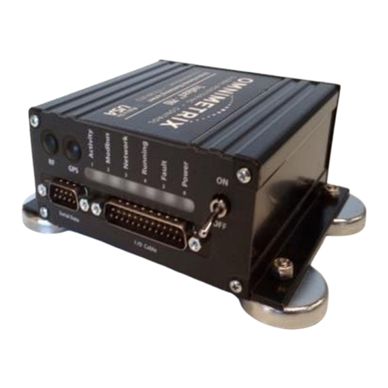
True Guard PRO
25-pin Data/Power
Cable
9-pin Data/Power Cable
IM-830-00
19-OCT-2021
Advertisement

Subscribe to Our Youtube Channel
Related Manuals for OmniMetrix TrueGuard PRO Nexus


Summary of Contents for OmniMetrix TrueGuard PRO Nexus
- Page 1 Power LED, check the antenna mount and cable connection. Allow 15 minutes for the monitor to log into the network, then call OmniMetrix® at 770-209-0012 to confirm installation. Access to machine data is through the OmniView® web interface at www.omnimetrix.net. Contact OmniMetrix for login instructions and web training.
- Page 2 White / Brown DC Ground Remote Start (see IM-1087 appendix-A) If you have any questions, please call OmniMetrix Tech Support at 770-209-0012 or email at techsupport@omnimetrixconnect.com . See the diagrams on the following pages for added wiring assistance. For Nexus and Evolution 1 & 2...
- Page 3 They close in a shutdown condition, indicating Common Alarm. In the Evolution 3, these two are pigtailed into a connector… see Page 4. 4295 Hamilton Mill Road, Suite 100 ▪ Buford, GA 30518 www.omnimetrix.net ▪ 770-209-0012 IM-830-00 19-OCT-2021 P a g e...
- Page 4 The Generac Red Wire on the Fuel Control Solenoid goes to +12 Vdc when running. Put the piggyback Faston connector provided on the OmniMetrix Red wire, replacing the fork connector. Then unplug the Generac red wire, attach it to the auxiliary blade on the piggyback connector and plug the pair back onto the solenoid as shown below.
- Page 5 In the newest Evolution machines, the Common Alarm wires are pigtailed as shown above. The OmniMetrix Blue wire goes to one terminal / wire, and the other terminal / wire gets a DC Ground wire.
- Page 6 Attaching to N1 or N2 will report lost utility. Attaching to T1 will report the home is unpowered. Optional AC Detector wiring diagram: TG PRO MONITOR 4295 Hamilton Mill Road, Suite 100 ▪ Buford, GA 30518 www.omnimetrix.net ▪ 770-209-0012 IM-830-00 19-OCT-2021 P a g e...
Need help?
Do you have a question about the TrueGuard PRO Nexus and is the answer not in the manual?
Questions and answers