Table of Contents
Advertisement
Quick Links
Neurostimulator
Axonics
®
and Axonics Sacral Neuromodulation System
Inc., registered or pending registration in the U.S. and other countries.
Axonics, Inc.
26 Technology Drive
Irvine, CA 92618 (USA)
www.axonics.com
Tel. +1 (877) 929-6642 (US and Canada)
Tel. +61 1800 954 009 (Australia)
Fax +1 (949) 396-6321
Implant Manual
Recharge-Free | Model 4101
®
are trademarks of Axonics,
Advertisement
Table of Contents

Subscribe to Our Youtube Channel
Related Manuals for Axonics F15


Summary of Contents for Axonics F15
- Page 1 Neurostimulator Implant Manual Recharge-Free | Model 4101 Axonics ® and Axonics Sacral Neuromodulation System ® are trademarks of Axonics, Inc., registered or pending registration in the U.S. and other countries. Axonics, Inc. 26 Technology Drive Irvine, CA 92618 (USA) www.axonics.com Tel.
-
Page 2: Label Symbols
This section explains the symbols found on the product and packaging. SYMBOL DESCRIPTION Axonics Neurostimulator Axonics Torque Wrench Neurostimulator default waveform with 14 Hz frequency, 0 mA amplitude and 210 µs pulse width Neurostimulator default electrode configuration: Electrode 0: negative (-) - Page 3 Media Authority (ACMA) regulatory arrangements and electrical equipment safety requirements US Federal Communications Commission device identification This device is packaged in two sterile barriers The Neurostimulator is connected to the Axonics Tined Lead Model 1201 (also included in Model 2201) Do not reuse...
-
Page 4: Table Of Contents
Clinical Environment ............................. 9 Neurostimulator Preparation........................9 Creating the Neurostimulator Pocket......................9 Connecting the Lead to the Neurostimulator ..................10 Implanting the Neurostimulator ........................11 Completing the Implant Procedure ......................12 Post-Surgery Management .........................12 Axonics® SNM System - Neurostimulator | Recharge-Free, Model 4101 Page 4... -
Page 5: Introduction
INTRODUCTION This manual provides information about the Axonics Sacral Neuromodulation (SNM) System Neurostimulator (Model 4101), which is a part of the Axonics SNM System. The Neurostimulator is connected to the Axonics Tined Lead (Model 1201 or 2201). INDICATIONS, WARNINGS, AND PRECAUTIONS •... -
Page 6: Storage And Usage Environment
Sterilization The contents of this package have been sterilized using ethylene oxide. This device is for single use only and should not be re-sterilized. Axonics® SNM System - Neurostimulator | Recharge-Free, Model 4101 Page 6... -
Page 7: Specifications
Setscrew Titanium Adhesive Silicone Torque wrench Torque wrench handle Polyetherimide Torque wrench shaft Stainless steel Note: The Neurostimulator case, which contains the electronics and power source, is hermetically sealed. Axonics® SNM System - Neurostimulator | Recharge-Free, Model 4101 Page 7... -
Page 8: X-Ray Identification
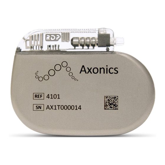
X-RAY IDENTIFICATION The radiopaque marker allows physicians to identify the manufacturer and model number under standard x-ray procedures. For the Axonics Neurostimulator, the designated code is RDP, which appears as light characters on a black background (Figure 2). Figure 2: The Axonics Neurostimulator radiopaque marker, “RDP”. -
Page 9: Neurostimulator Implant Procedure
NEUROSTIMULATOR IMPLANT PROCEDURE The following section describes the procedure for implanting the Axonics Neurostimulator. This procedure should be performed when an Axonics tined lead has already been implanted. Procedure Supplies In addition to the general surgical tools required by the physician, the following supplies are needed for the preparation, implantation, programming, and Remote Control pairing of the Neurostimulator: •... -
Page 10: Connecting The Lead To The Neurostimulator
Marker D on the lead should be inside the Neurostimulator strain relief (Figure 5). The retention sleeve on the tined lead should be positioned under the Neurostimulator setscrew. Figure 5: Insert Lead Fully into the Neurostimulator Connector Block. Axonics® SNM System - Neurostimulator | Recharge-Free, Model 4101 Page 10... -
Page 11: Implanting The Neurostimulator
Neurostimulator (Figure 7) or place under the Neurostimulator to minimize interference with telemetry Caution during programming. Figure 7: Wrap Excess Lead Around or Under, but not on Top of, the Neurostimulator. Axonics® SNM System - Neurostimulator | Recharge-Free, Model 4101 Page 11... -
Page 12: Completing The Implant Procedure
The patient should carry the Remote Control at all times to be able to adjust or turn off the Neurostimulator. Caution 5. Complete the system registration paperwork and return to Axonics. 6. Schedule the patient’s follow-up visits at regular intervals to ensure that the stimulation is programmed optimally. -
Page 13: Wireless Communication
Meteorological Satellite, and Earth Exploration Satellite Services and must accept any interference received, including interference that may cause undesired operation. Note: Changes and modifications to the Neurostimulator are not authorized by Axonics could void FCC and IC certification and negate the user’s authority to use the product. -
Page 14: Customer Service
CUSTOMER SERVICE For questions regarding the Axonics SNM System, please contact our Customer Support Center: · In the US and Canada, call toll-free at +1-877-929-6642 · In Australia, call +61 1800 954 009 · For all regions, email customersupport@axonics.com Additional information and product manuals can be found at our website: www.axonics.com 2024-05 All Rights Reserved.
Need help?
Do you have a question about the F15 and is the answer not in the manual?
Questions and answers