Table of Contents
Advertisement
Quick Links
Specification
SB-FC1000L [For front speaker (left)]
SB-FC1000R [For front speaker (right)]
Front speaker section
Type
Speaker
Woofer (1 & 2)
Tweeter (1)
Super tweeter
Impedance
Input power (IEC)
Sound pressure level
Crossover frequency
Frequency range
Center speaker section
Type
Speakers
Woofer (3)
Midrange
Tweeter (2)
Impedance
Input power (IEC)
Sound pressure level
3 way 4 speaker system Bass-
reflex type
8 cm cone type x 2
2.5 cm dome type x 1
1.2 cm dome type x 1
6 Ω
200 W (Max), 100 W (RATED)
82.5 dB/W (1.0 m)
2.5 kHz, 20 kHz
65 Hz - 100 kHz (at -16 dB)
75 Hz - 90 kHz (at -10 dB)
3 way 3 speaker system Bass-
reflex type
8 cm cone type x 1
6.5 cm cone type x 1
2.5 cm dome type x 1
12 Ω
100 W (Max), 50 W (RATED)
80 dB/W (1.0 m)
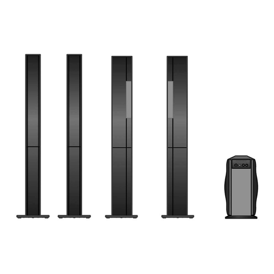
SB-FS1000E
SB-FC1000LE
SB-FC1000RE
SB-HS1000E
SB-WA1000E
SB-TP1000E
Colour
(K)... Black Type
Crossover frequency
Frequency range
General
Dimensions (W x H x D)
Mass
SB-HS1000E (For surround speakers)
Type
Speakers
Woofer (1 & 2)
Tweeter
Impedance
Input power (IEC)
Sound pressure level
Crossover frequency
Frequency range
Dimensions (W x H x D)
© 2008 Matsushita Electric Industrial Co. Ltd.. All
rights
reserved.
distribution is a violation of law.
ORDER NO. MD0807010CE
Speaker System
800 Hz, 3 kHz
65 Hz - 50 kHz (at -16 dB)
75 Hz - 40 kHz (at -10 dB)
279 mm x 1298 mm x 279 mm
(with the stand)
175 mm x 802 mm x 102 mm (For
wall-mounting)
Approx. 12.6 kg (with the stand)
Approx. 5.4 kg (For wall-mounting)
2 way 3 speaker system Bass-
reflex type
8 cm cone type x 2
2.5 cm dome type x 1
200 W (Max), 100 W (RATED)
82.5 dB/W (1.0 m)
2.5 kHz
65 Hz - 50 kHz (at -16 dB)
75 Hz - 40 kHz (at -10 dB)
279 mm x 1298 mm x 279 mm
(with the stand)
Unauthorized
copying
and
6 Ω
Advertisement
Table of Contents

Related Manuals for Panasonic SB-FS1000E


Summary of Contents for Panasonic SB-FS1000E
- Page 1 ORDER NO. MD0807010CE Speaker System SB-FS1000E SB-FC1000LE SB-FC1000RE SB-HS1000E SB-WA1000E SB-TP1000E Colour (K)... Black Type Specification SB-FC1000L [For front speaker (left)] Crossover frequency 800 Hz, 3 kHz SB-FC1000R [For front speaker (right)] Frequency range 65 Hz - 50 kHz (at -16 dB)
-
Page 2: Table Of Contents
SB-FS1000E / SB-FC1000LE / SB-FC1000R E / SB-HS1000E / SB-WA1000E / SB-TP1000E 125 mm x 802 mm x 87 mm (For Phase switching NORMAL/REVERSE wall-mounting) Low pass filter 50 Hz - 200 Hz Variable Mass Approx. 9.3 kg (with the stand) Approx. -
Page 3: Safety Precautions
SB-FS1000E / SB-FC1000LE / SB-FC1000R E / SB-HS1000E / SB-WA1000E / SB-TP1000E 1 Safety Precautions 1.1. General Guidelines 1. When servicing, observe the original lead dress. If a short circuit is found, replace all parts which have been overheated or damaged by the short circuit. -
Page 4: Caution For Ac Cord
SB-FS1000E / SB-FC1000LE / SB-FC1000R E / SB-HS1000E / SB-WA1000E / SB-TP1000E 1.2. Caution for AC Cord... -
Page 5: Protection Circuitry
SB-FS1000E / SB-FC1000LE / SB-FC1000R E / SB-HS1000E / SB-WA1000E / SB-TP1000E 1.3. Before Repair and Adjustment (For SB-WA1000E-K) Disconnect AC power, discharge Power Supply Capacitors C508 & C703 through a 10Ω, 1W resistor to ground. DO NOT SHORT-CIRCUIT DIRECTLY (with a screwdriver blade, for instance), as this may destroy solid state devices. -
Page 6: Prevention Of Electrostatic Discharge (Esd) To Electrostatically Sensitive (Es) Devices
SB-FS1000E / SB-FC1000LE / SB-FC1000R E / SB-HS1000E / SB-WA1000E / SB-TP1000E 2 Prevention of Electro Static Discharge (ESD) to Electrostatically Sensitive (ES) Devices Some semiconductor (solid state) devices can be damaged easily by electricity. Such components commonly are called Electrostatically Sensitive (ES) Devices. -
Page 7: About Lead-Free Solder (Pbf)
SB-FS1000E / SB-FC1000LE / SB-FC1000R E / SB-HS1000E / SB-WA1000E / SB-TP1000E 3 About Lead-Free Solder (PbF) 3.1. Service caution based on legal restrictions 3.1.1. General description about Lead Free Solder (PbF) The lead free solder has been used in the mounting process of all electrical components on the printed circuit boards used for this equipment in considering the globally environmental conservation. -
Page 8: Accessories
SB-FS1000E / SB-FC1000LE / SB-FC1000R E / SB-HS1000E / SB-WA1000E / SB-TP1000E 4 Accessories SB-FS1000E-K Spacers..16 pcs Speaker cables (long: 10m)..2 pcs Nylon clamp..6 pcs Speaker cables (short: 6m)..2 pcs Screw for nylon clamp..6 pcs Center speaker cable (approx. -
Page 9: Operating Instructions Procedures
SB-FS1000E / SB-FC1000LE / SB-FC1000R E / SB-HS1000E / SB-WA1000E / SB-TP1000E 5 Operating Instructions Procedures 5.1. Location... -
Page 10: Assembly And Installation
SB-FS1000E / SB-FC1000LE / SB-FC1000R E / SB-HS1000E / SB-WA1000E / SB-TP1000E 5.2. Assembly and Installation... - Page 11 SB-FS1000E / SB-FC1000LE / SB-FC1000R E / SB-HS1000E / SB-WA1000E / SB-TP1000E...
-
Page 12: Subwoofer Operation
SB-FS1000E / SB-FC1000LE / SB-FC1000R E / SB-HS1000E / SB-WA1000E / SB-TP1000E 5.3. Subwoofer operation... - Page 13 SB-FS1000E / SB-FC1000LE / SB-FC1000R E / SB-HS1000E / SB-WA1000E / SB-TP1000E 5.3.1. Connection of the Speaker Cables...
-
Page 14: Assembling And Disassembling
SB-FS1000E / SB-FC1000LE / SB-FC1000R E / SB-HS1000E / SB-WA1000E / SB-TP1000E 6 Assembling and Disassembling “ATTENTION SERVICER” Some chassis components may have sharp edges. Be careful when disassembling and servicing. 1. This section describes procedures for checking the operation and replacing the main components. - Page 15 SB-FS1000E / SB-FC1000LE / SB-FC1000R E / SB-HS1000E / SB-WA1000E / SB-TP1000E...
-
Page 16: Disassembly Flow Chart
SB-FS1000E / SB-FC1000LE / SB-FC1000R E / SB-HS1000E / SB-WA1000E / SB-TP1000E 6.1. Disassembly flow chart The following chart is the procedure for disassembling the casing and inside parts for internal inspection when carrying out the servicing. To assemble the unit, reverse the steps shown in the chart as below. - Page 17 SB-FS1000E / SB-FC1000LE / SB-FC1000R E / SB-HS1000E / SB-WA1000E / SB-TP1000E 6.2. SB-FC1000LE-K/SB-FC1000RE- the stand base. Step 5: Remove front speaker from 2 projections of the K (For Front Speakers) speaker stand. 6.2.1. Disassembly of Stand base The illustration shows disassembly for both left and right front speakers.
- Page 18 SB-FS1000E / SB-FC1000LE / SB-FC1000R E / SB-HS1000E / SB-WA1000E / SB-TP1000E 6.2.2. Disassembly of Main net frame assembly Step 4: Remove main net frame assembly. Caution: Do not exert strong force as it may damage the main net frame Step 1: Insert flathead screwdriver into the gap between front assembly.
- Page 19 SB-FS1000E / SB-FC1000LE / SB-FC1000R E / SB-HS1000E / SB-WA1000E / SB-TP1000E 6.2.3. Disassembly of Front woofer 6.2.4. Disassembly of Super tweeter speaker 1 (SP3) speaker (SP5) Follow (step 1) to (step 4) in Item 6.2.2. Follow (step 1) to (step 4) in Item 6.2.2.
- Page 20 SB-FS1000E / SB-FC1000LE / SB-FC1000R E / SB-HS1000E / SB-WA1000E / SB-TP1000E 6.2.5. Disassembly of Tweeter speaker 1 6.2.6. Disassembly of Center speaker (SP1) (SP4) Follow (step 1) to (step 4) in Item 6.2.2. Follow (step 1) to (step 4) in Item 6.2.2.
- Page 21 SB-FS1000E / SB-FC1000LE / SB-FC1000R E / SB-HS1000E / SB-WA1000E / SB-TP1000E 6.2.7. Disassembly of Front woofer 6.2.8. Disassembly of Net assembly speaker 2 (SP3) Follow (step 1) to (step 4) in Item 6.2.2. Follow (step 1) to (step 4) in Item 6.2.2.
- Page 22 SB-FS1000E / SB-FC1000LE / SB-FC1000R E / SB-HS1000E / SB-WA1000E / SB-TP1000E 6.2.9. Disassembly of Tweeter speaker 2 6.2.10. Disassembly of Mid-range speaker (SP1) (SP2) Follow (step 1) to (step 4) in Item 6.2.2. Follow (step 1) to (step 4) in Item 6.2.2.
- Page 23 SB-FS1000E / SB-FC1000LE / SB-FC1000R E / SB-HS1000E / SB-WA1000E / SB-TP1000E 6.2.11. Disassembly of Bottom cover 6.2.12. Disassembly of Network assembly (PCB1) Step 1: Remove 3 screws. Step 1: Remove PS cover. Step 2: Remove bottom cover. Step 2: Remove 2 screws.
- Page 24 SB-FS1000E / SB-FC1000LE / SB-FC1000R E / SB-HS1000E / SB-WA1000E / SB-TP1000E Step 8: Remove the network assembly (PCB1). Step 4: Remove 2 screws. Step 5: Pull out the network assembly (PCB1) slightly as arrow shown. Step 6: Detach all wires.
- Page 25 SB-FS1000E / SB-FC1000LE / SB-FC1000R E / SB-HS1000E / SB-WA1000E / SB-TP1000E 6.3. SB-HS1000E-K (For surround the stand base. Step 5: Remove the surround speaker from 2 projections of the speaker) speaker stand. 6.3.1. Disassembly of Stand base Note: This section is applicable if the complete speaker is sent in together during repairs.
- Page 26 SB-FS1000E / SB-FC1000LE / SB-FC1000R E / SB-HS1000E / SB-WA1000E / SB-TP1000E 6.3.2. Disassembly of Main net frame 6.3.3. Disassembly of Front woofer assembly speaker 1 (SP2) Follow (step 1) to (step 4) in Item 6.3.2. Step 1: Insert flathhead screwdriver into the gap between surround speaker and main net frame assembly.
- Page 27 SB-FS1000E / SB-FC1000LE / SB-FC1000R E / SB-HS1000E / SB-WA1000E / SB-TP1000E 6.3.4. Disassembly of Tweeter speaker (SP1) Follow (step 1) to (step 4) in Item 6.3.2. Step 4: Remove the front woofer speaker 1(SP2). Step 1: Remove 4 screws.
- Page 28 SB-FS1000E / SB-FC1000LE / SB-FC1000R E / SB-HS1000E / SB-WA1000E / SB-TP1000E 6.3.5. Disassembly of Front woofer speaker 2 (SP2) Follow (step 1) to (step 4) in Item 6.3.2. Step 4: Remove tweeter speaker (SP1). Step 1: Remove 4 screws.
- Page 29 SB-FS1000E / SB-FC1000LE / SB-FC1000R E / SB-HS1000E / SB-WA1000E / SB-TP1000E 6.3.6. Disassembly of Bottom cover Step 4: Remove front woofer speaker 2 (SP2). Step 1: Remove 2 screws. Step 2: Remove the bottom cover.
- Page 30 SB-FS1000E / SB-FC1000LE / SB-FC1000R E / SB-HS1000E / SB-WA1000E / SB-TP1000E 6.4. SB-WA1000E-K (For Active 6.4.2. Disassembly of Woofer unit 1 (SP1) subwoofer) Follow (step 1) in item 6.4.1. 6.4.1. Disassembly of Front net frame unit Step 1: Remove 4 screws.
- Page 31 SB-FS1000E / SB-FC1000LE / SB-FC1000R E / SB-HS1000E / SB-WA1000E / SB-TP1000E 6.4.3. Disassembly of Rear net frame 6.4.4. Disassembly of Woofer unit 2 unit (SP1) Follow (step 1) in item 6.4.3. Step 1: Remove the rear net frame unit.
- Page 32 SB-FS1000E / SB-FC1000LE / SB-FC1000R E / SB-HS1000E / SB-WA1000E / SB-TP1000E 6.4.5. Disassembly and checking of Step 3: Remove the control panel unit from the front net frame as arrow shown. Panel P.C.B and LED P.C.B. Follow (step 1) in item 6.4.1.
- Page 33 SB-FS1000E / SB-FC1000LE / SB-FC1000R E / SB-HS1000E / SB-WA1000E / SB-TP1000E Step 12: Remove the volume angle as arrow shown. Step 9: Cover with a soft cloth and pull out the selector knob and power knob as arrow shown.
- Page 34 SB-FS1000E / SB-FC1000LE / SB-FC1000R E / SB-HS1000E / SB-WA1000E / SB-TP1000E 6.4.6. Disassembly of the Stand base Step 1: Remove 4 screws. Step 3 : Remove 2 screws. Step 2: Remove the stand base. 6.4.7. Disassembly of Amp unit Follow (step 1) to (step 2) in item 6.4.6.
- Page 35 SB-FS1000E / SB-FC1000LE / SB-FC1000R E / SB-HS1000E / SB-WA1000E / SB-TP1000E 6.4.8. Disassembly of Rear panel assembly Follow (step 1) to (step 2) in item 6.4.6. Follow (step 1) to (step 7) in item 6.4.7. Step 6 : Disconnect the connectors CN601, CN602, CN502A and CN101A.
- Page 36 SB-FS1000E / SB-FC1000LE / SB-FC1000R E / SB-HS1000E / SB-WA1000E / SB-TP1000E 6.4.9. Disassembly of Fan unit 6.4.10. Disassembly and checking of Power P.C.B, Main P.C.B and Follow (step 1) to (step 2) in item 6.4.6. Transformer P.C.B. Follow (step 1) to (step 7) in item 6.4.7.
- Page 37 SB-FS1000E / SB-FC1000LE / SB-FC1000R E / SB-HS1000E / SB-WA1000E / SB-TP1000E Step 7: Reconnect the main P.C.B., transformer P.C.B. and Step 3: Detach the connector CP603. power P.C.B. for checking. Step 4: Pull out the power P.C.B. as arrow shown.
- Page 38 SB-FS1000E / SB-FC1000LE / SB-FC1000R E / SB-HS1000E / SB-WA1000E / SB-TP1000E 6.4.11. Replacement of the Power IC Follow (step 1) to (step 2) in item 6.4.6. Follow (step 1) to (step 7) in item 6.4.7. Follow (step 1) to (step 2) in item 6.4.8.
-
Page 39: Voltage Measurement And Waveform Chart
SB-FS1000E / SB-FC1000LE / SB-FC1000R E / SB-HS1000E / SB-WA1000E / SB-TP1000E 7 Voltage Measurement and Waveform Chart Note: • Indicated voltage values are the standard values for the unit measured by the DC electronic circuit tester (high-impedance) with the chassis taken as standard. - Page 40 SB-FS1000E / SB-FC1000LE / SB-FC1000R E / SB-HS1000E / SB-WA1000E / SB-TP1000E 7.1.3. Power P.C.B. POWER P.C.B. Q701 Q702 Q703 Q704 Ref No. MODE TUNER 11.0 -11.3 -0.5 11.0 13.8 11.7 -10.7 -18.4 -11.4 STANDBY SB-WA1000E-K POWER P.C.B.
-
Page 41: Waveform Chart
SB-FS1000E / SB-FC1000LE / SB-FC1000R E / SB-HS1000E / SB-WA1000E / SB-TP1000E 7.2. Waveform Chart IC101 PIN1 IC101 PIN 2 IC101 PIN 5 IC101 PIN 7 TUNER PLAY TUNER PLAY TUNER PLAY TUNER PLAY 148mVp-p (10usec.div) 142mVp-p (10usec.div) 159mVp-p (10usec.div) 142mVp-p (10usec.div) -
Page 42: Connection Of Speaker Wiring
SB-FS1000E / SB-FC1000LE / SB-FC1000R E / SB-HS1000E / SB-WA1000E / SB-TP1000E 8 Connection of Speaker wiring 8.1. SB-FC1000LE-K/SB-FC1000RE-K (Front speakers) TW + (YELLOW) Tweeter speaker (SP1) TW - (BLACK) MD + (ORANGE) Mid-range IN + (RED) speaker (SP2) MD - (BLUE) PSW1 2.7mH... -
Page 43: Wiring Connection Diagram
SB-FS1000E / SB-FC1000LE / SB-FC1000R E / SB-HS1000E / SB-WA1000E / SB-TP1000E 9 Wiring Connection Diagram 9.1. SB-WA1000E-K PANEL P.C.B. LOW PASS VOLUME POWER PHASE FILTER ENCODER LED P.C.B. 7.......1 SOLDER SIDE SOLDER SIDE MAIN P.C.B. INPUTS SPEAKER WOOFER 2... - Page 44 SB-FS1000E / SB-FC1000LE / SB-FC1000R E / SB-HS1000E / SB-WA1000E / SB-TP1000E...
-
Page 45: Block Diagram
SB-FS1000E / SB-FC1000LE / SB-FC1000R E / SB-HS1000E / SB-WA1000E / SB-TP1000E 10 Block Diagram IC101 C0ABBB000216 JK101 Q703 Q702,Q704 S501 Q701 Q603 T702 Q409 L701 IC502 Q202 Q201 Q501 IC201 Q502 C0ABBB000216 Q602 Q851 Q803 <+5V> REGULATOR SWITCH Q301... - Page 46 SB-FS1000E / SB-FC1000LE / SB-FC1000R E / SB-HS1000E / SB-WA1000E / SB-TP1000E...
-
Page 47: Notes Of Schematic Diagram
SB-FS1000E / SB-FC1000LE / SB-FC1000R E / SB-HS1000E / SB-WA1000E / SB-TP1000E 11 Notes Of Schematic Diagram (All schematic diagrams may be modified at any time with the development of new technology) Notes: S501 : Phase Switch ( NORMAL REVERSE) - Page 48 SB-FS1000E / SB-FC1000LE / SB-FC1000R E / SB-HS1000E / SB-WA1000E / SB-TP1000E...
-
Page 49: Schematic Diagram
SB-FS1000E / SB-FC1000LE / SB-FC1000R E / SB-HS1000E / SB-WA1000E / SB-TP1000E 12 Schematic Diagram 12.1. Main Circuit 3#(%7!<8#6$8!':!7646) 67!896#8:#;8< =6>6"638'9!?6?89% =646"638'9!?6?89% =7!89638'9!?6?89% $)2) "2!##E22222- GE)2) :)2* #)2* $)2* "2!##E22222- *F*E -2J) 89A;<3 #9)2)! :)2- :)2. :)20 ,F/E ,F/E "... - Page 50 SB-FS1000E / SB-FC1000LE / SB-FC1000R E / SB-HS1000E / SB-WA1000E / SB-TP1000E 12.2. Panel Circuit, LED Circuit and Transformer Circuit 3#(%7!<8#6$8!':!7646* 6A!9%?6#8:#;8< 6?%$6#8:#;8< =6>6"638'9!?6?89% =646"638'9!?6?89% J:-2) $*"$"),"222. J:-2* J@?;7%6%9#@$%: $*"$$),"222* :-2- :-2. ?@56A!336&8?<%: *F/E *F/E $-2) H-2)IH-2* 3-2) "+!E!222222. :-2+ A(!3% "8'##&GG22).
- Page 51 SB-FS1000E / SB-FC1000LE / SB-FC1000R E / SB-HS1000E / SB-WA1000E / SB-TP1000E 12.3. Power Circuit 3#(%7!<8#6$8!':!7646+ 6A@5%:6#8:#;8< =6>6"638'9!?6?89% =646"638'9!?6?89% <@ A!9%?6#8:#;8<B#9-2*"C 8963#(%7!<8#6$8!':!74* #9-2*! " " #9.2+ 4))J $/2- H/2+ <@ 7!N0)*227? A5:6:%?!L 7!896#8:#;8< H/2)IH/2+ B#A.2+C :/2- H/2) *F/K *3$2-1*!:! 8963#(%7!<8# >))J...
- Page 52 SB-FS1000E / SB-FC1000LE / SB-FC1000R E / SB-HS1000E / SB-WA1000E / SB-TP1000E...
-
Page 53: Printed Circuit Board
SB-FS1000E / SB-FC1000LE / SB-FC1000R E / SB-HS1000E / SB-WA1000E / SB-TP1000E 13 Printed Circuit Board 13.1. Main P.C.B. MAIN P.C.B (REPV0128C) Q852 C625 C853 C902 D407 Q409 CN850 IC850 D409 E601 (FOR SOFTWARE D408 C849 DOWNLOADING) Q603 Q602 CP603... - Page 54 SB-FS1000E / SB-FC1000LE / SB-FC1000R E / SB-HS1000E / SB-WA1000E / SB-TP1000E 13.2. PANEL/ LED/ TRANSFORMER/ POWER P.C.B. PANEL P.C.B (REPV0048A) TRANSFORMER P.C.B (REPV0128C) T701 LOW PASS VOLUME 250V T2AL (POWER TRANSFORMER) ENCODER FILTER VR502 VR501 S502 W501 (POWER) (BLU)
-
Page 55: Illustration Of Ic's, Transistors And Diodes
SB-FS1000E / SB-FC1000LE / SB-FC1000R E / SB-HS1000E / SB-WA1000E / SB-TP1000E 14 Illustration of IC’s, Transistors and Diodes... - Page 56 SB-FS1000E / SB-FC1000LE / SB-FC1000R E / SB-HS1000E / SB-WA1000E / SB-TP1000E...
-
Page 57: Exploded View
SB-FS1000E / SB-FC1000LE / SB-FC1000R E / SB-HS1000E / SB-WA1000E / SB-TP1000E 15 Exploded view 15.1. Cabinet Parts Location (SB-FC1000LE-K/SB-FC1000RE-K) (Front speakers) - Page 58 SB-FS1000E / SB-FC1000LE / SB-FC1000R E / SB-HS1000E / SB-WA1000E / SB-TP1000E 15.2. Cabinet Parts Location (SB-HS1000E-K) (Surround speaker)
- Page 59 SB-FS1000E / SB-FC1000LE / SB-FC1000R E / SB-HS1000E / SB-WA1000E / SB-TP1000E 15.3. Cabinet Parts Location (SB-WA1000E-K) (Active subwoofer)
- Page 60 SB-FS1000E / SB-FC1000LE / SB-FC1000R E / SB-HS1000E / SB-WA1000E / SB-TP1000E 15.4. Packaging (SB-FS1000E-K)
- Page 61 SB-FS1000E / SB-FC1000LE / SB-FC1000R E / SB-HS1000E / SB-WA1000E / SB-TP1000E 15.5. Packaging (SB-FS1000E-K and SB-WA1000E-K)
- Page 62 SB-FS1000E / SB-FC1000LE / SB-FC1000R E / SB-HS1000E / SB-WA1000E / SB-TP1000E...
-
Page 63: Replacement Parts List
SB-FS1000E / SB-FC1000LE / SB-FC1000R E / SB-HS1000E / SB-WA1000E / SB-TP1000E 16 Replacement Parts List Notes: • Important safety notice: Components identified by mark have special characteristics important for safety. Furthermore, special parts which have purposes of fire-retardent (resistors), high-quality sound (capacitors), low noise (resistors), etc are used. - Page 64 SB-FS1000E / SB-FC1000LE / SB-FC1000R E / SB-HS1000E / SB-WA1000E / SB-TP1000E Ref. Part No. Part Name & Description Remarks 16.3. SB-WA1000E (Active subwoofer) RKA0191-K WALL SPACER RMR1503-K NYLON CLAMPER Ref. Part No. Part Name & Description Remarks XTW3+10JFJK SCREW...
- Page 65 SB-FS1000E / SB-FC1000LE / SB-FC1000R E / SB-HS1000E / SB-WA1000E / SB-TP1000E Ref. Part No. Part Name & Description Remarks Ref. Part No. Part Name & Description Remarks RJLV1P001B50 MONAURAL CONNECTION CABLE D501 B3AKA0000006 DIODE RQT9219-E O/I BOOK D601 B0EAMM000038...
- Page 66 SB-FS1000E / SB-FC1000LE / SB-FC1000R E / SB-HS1000E / SB-WA1000E / SB-TP1000E Ref. Part No. Part Name & Description Remarks Ref. Part No. Part Name & Description Remarks HOLDERS R406 D0GB562JA007 5.6K 1/10W R407 ERJ3GEYJ103V 10K 1/10W H604 K1YF12000002 12P WIRE HOLDER...
- Page 67 SB-FS1000E / SB-FC1000LE / SB-FC1000R E / SB-HS1000E / SB-WA1000E / SB-TP1000E Ref. Part No. Part Name & Description Remarks Ref. Part No. Part Name & Description Remarks C102 ECA1HAK010XB 1uF 50V C705 ECA1CAK100XB 10uF 16V C103 F1H1H221A748 220pF 50V...
Need help?
Do you have a question about the SB-FS1000E and is the answer not in the manual?
Questions and answers