
Related Manuals for DVDO DVDO-Camera-Ctl-2


Summary of Contents for DVDO DVDO-Camera-Ctl-2
- Page 1 DVDO-Camera-Ctl-2 IP PTZ Camera Controller with Joystick User Manual Version v1.0 DVDO │ +1.408.213.6680 │ support@dvdo.com │ www.dvdo.com...
- Page 2 Thank you for purchasing DVDO-Camera-Ctl-2 For optimum performance and safety, please read these instructions carefully before connecting, operating or adjusting this product. Please keep this manual for future reference. reference. Surge protection device recommended This product contains sensitive electrical components that may be damaged by electrical spikes, surges, electric shock, lighting strikes, etc.
-
Page 3: Product Overview
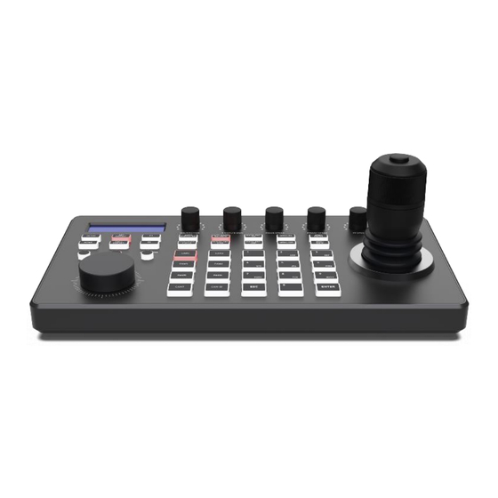
1. Product Overview 1.1 Description DVDO-Camera-Ctl-2 is a PTZ camera controller with a joystick, an LCD screen as well as multiple knobs and backlit buttons. It can control up to 255 PTZ cameras over IP and/or serial (hybrid). Controls include Pan, Tilt, Zoom, PTZ speed, Focus, Iris, White Balance and R/B color correction. The web-based GUI allows easy set up and configuration of the cameras. -
Page 4: Product Interface Description
2. Product Interface Description 2.1 Interface Description Power Button Tally / Contact IP port / RJ45 port (controller power switch) Tally control port Connect the controller to the Network/PoE RS-422/485 Control RJ-45 Interface 12V DC Power Input Interface Connect RS-422 control cable, up to control 7 Wide voltage range: DC9V-DC18V RS-232 Interface device Daisy-chained Rs-422 cameras;... -
Page 5: Button Function Description
3. Button Function Description 3.1 Functional Button Desctiption Camera Function Section HOME: Home MENU ON: Menu On AUTO EXPOSURE: Auto Exposure MENU OFF: Menu Off EXPOSURE CYCLE: Exposure adjust Auto MENU ENTER: Menu Confirm AUTO WHITE BALANCE: white balance White MENU BACK: Menu Back WHITE BALANCE CYCLE:... - Page 6 Knob Function Section Controller Functional Button SETUP: Set controller native settings IRIS/SHUTTER: Aperture/Shutter adjust CALL PRESET: Call preset R GAIN: gain CAM ID: Camera address B GAIN: Blue gain ESC: Exit FOCUSSPEED: Focus speed adjust ENTER: Confirm PRESETSPEED: Preset speed adjust PT Number Key, IP, Preset, etc NUMBER0-9 ZOOM SPEED:...
- Page 7 3.2 Description of Rotary Joystick Operate Output Operate Output Operate Output Down Left Operate Output Operate Output Operate Output Right Zoom + Zoom - Joystick [Up, Down, Left, Right]: Control the PTZ to turn up, down, left and tight. Joystick [rotate left and right]: Rotate the joystick to zoom function, rotate right to zoom +, zoom 4.
- Page 8 > Network mode connection diagram The controller and PTZ camera are connected in the same LAN, and the IP addresses are in the same network segment, such as: 192.168.1.123 and 192.168.1.111. Belong to the same network segment; If not in the same LAN, you need to modify the IP address of the controller or camera at first, the default IP acquisition method of the controller is get it dynamically.
- Page 9 > Analog Mode Connection Diagram (1) Analog Mode RS232 POWER RS232 interface is RJ45 Network port to 9-pin round hole male MD8M(PIN) Male head RJ45 Male head (2) Analog Mode RS485/RS422 POWER 1 2 3 4 5 6 7 8 -08-...
-
Page 10: Network Configuration
5. Network Configuration 5.1 First connection and login The controller and PTZ camera are connected in the same LAN, and the IP addresses are in the same network segment, such as: 192.168.1.123 and 192.168.1.111. Belong to the same network segment; If not in the same LAN, you need to modify the IP address of the controller or camera at first , the default IP acquisition method of the controller is get it dynamically. - Page 11 (Enter device number, corresponding IP address, port number and username click save.) Notice: When entering the controller web and add device successfully is synchronized with controller, in the web page adds the device successfully then click the controller corresponding to the number to control the dome camera.
-
Page 12: System Upgrade
Dynamic address (DHCP) (default acquisition method): The controller will automatically request an IP address from the router. After the request is successful, it will be displayed on the display screen of the controller. The displayed format is "Local IP: XXX,XXX,XXX,XXX". 5.3 System Upgrade The upgrade function is used as a maintenance and update controller function. -
Page 13: Import Configuration
5.5 Restart When the device has been running for a long time and needs to be restarted for maintenance, click Restart to achieve the purpose of restarting maintenance. 5.6 Import Configuration Import the device information of the previous controller (for example, when adding multiple devices to the previous controller, export the file type, and use it as an import to another device when adding a new controller). -
Page 14: Export Information
5.7 Export information Export information about adding multiple devices to the current controller, which can be exported to other controller devices for use. 5.8 Version Information Display the hardware and software information of the current controller. -13-... - Page 15 6. FAQs 1. When the screen displays "Connection Failed", please check whether the device corresponding to this IP is connected normally in the LAN. 2. When the screen displays "Username password error", please check whether the username and password of the added device are correct. 3.
- Page 16 Follow us DVDO │ +1.408.213.6680 │ support@dvdo.com │ www.dvdo.com...
Need help?
Do you have a question about the DVDO-Camera-Ctl-2 and is the answer not in the manual?
Questions and answers