Advertisement
Quick Links
gt
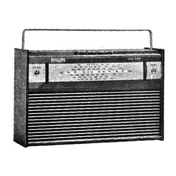
PHILIPS
PHILIPS
181-195
HEAD OFFICE:
WAKEFIELD STREET.
5-7
AUCKLAND
BRANCH:
CHRISTCHURCH
BRANCH: 77 FERRY ROAD.
GENERAL
Power Supply
Philips Power Pack
v.
9
Controls
Four pushbuttons
Tuning and volume knobs.
speaker
The
(1)
With volume control
(2)
at
an ambient temperature
supply
adjust the collector
To
(3)
Turn
Volume
(a)
Turn trimpot
(b)
Insert
(c)
Adjust
(d)
means
adjustment
been
replaced.
the
position
(4)
For
ALIGNMENT INSTRUCTIONS
condenser
Turn
tuning
maximum. Keep the audio output
operations.
alignment
all cores
Screw out
Trimming Frequency
455
Kc
Modulated
30%
455
Kc
Modulated
30%
R.
CIRCUIT ALIGNMENT
F
.
local oscillator
The
.
to
512
Coverage
signal generator
Connect
Trimming Frequency
512
Kc
Modulated
30%
1635
Kc
Modulated
30%
Repeat the
Alignment once more
RF
TRIMMER LOCATION DIAGRAM.
VOL CONTROL
I
I4
DRIVE CORD ASSY.
ELECTRICAL
INDUSTRIES
WELLINGTON. G.P.O.
AUCKLAND.
HARGREAVES STREET,
CHRISTCHURCH.
ER4304 or
Eveready
765
treble, bass
off, on,
impedance is
ohms.
8
the
total
current consumption
minimum
20°C should be between
of
the output
current
of
to
Control down
minimum.
to
the right
against stop.
R23
meter (range 10Ma) in
collector-line
collector
current
of
TR 7 (AC
to
at
an ambient temperature
of
trimpot
R23
Ma
3
should not be normally
coils see
of trimmers and
capacity
(higher frequency) and the volume control
to
minimum
level constant at
LP.
of
transformers
except
Connect Signal Generator
to base
Via 33K pfd
base
Via 33K pfd
to
at
a higher frequency than the
is
1635 Kc.
aerial to
Standard
Via
Dummy
Gang Position
closed.
Fully
Maximum
Fully open°
capacity
Minimum
as above.
3RD.IF?.
ND. IFT.
1
"15
"3.".
LILIZ.
LISJLO
"U
OFF
BASS
YREILE
SKJ.
5K1.
SKA.
TUNING CONDENSER
CAPACITY
MAXIMUM
AT
mica
OF NEW ZEALAND
BOX
2097. PHONE 57-250.
5124. PHONE 34-410.
P.O. BOX
PO.
1488. PHONE 65-244.
BOX
Speaker
Battery.
Eliptical,
6"
't
C'
in
"cm
ry us
the
set
of
and
12
transistors
as follows:-
proceed
,
at
of
point
on
TR 6
X
at
battery voltage
128)
a
of
20°C.
of
necessary unless
transistors
the
location diagrams.
the trimmer
approximately
50 Mw
during
L15-Ll6 and L7-L8.
Adjust for Max. Output
Cores L15-L16, L11-12
TR 2
L13-l4.
&
Cores L7-8 and
TR
1
L9-10.
signal
frequency.
aerial socket
the
of
for Max. Output
Trim
oscillator
L4~6
L2-3
aerial coil
capacity
oscillator
L11
aerial
trimmer
C
7
I.
L 2
.
"011:...
ISI'.IFT.
.
.0.
O
T INNER
ml
nu
SECTION
SECTION
GANG
TUNING
ON
I
SKA.
|
I
-————/€
PHILIPS
LIMITED
23
watts
ohms,
8
6
transist
diode
'
5.
or
, 3
g
7
with
volt
9
M/a.
16
circuit.
volt by
9
This
have
'
to
receiver.
core
rod
on
trimmer
475
RL
Advertisement

Related Manuals for Philips 23 RL 475


Summary of Contents for Philips 23 RL 475
- Page 1 AUCKLAND BRANCH: AUCKLAND. 5124. PHONE 34-410. HARGREAVES STREET, P.O. BOX CHRISTCHURCH BRANCH: 77 FERRY ROAD. CHRISTCHURCH. 1488. PHONE 65-244. GENERAL Power Supply Speaker Philips Power Pack ER4304 or Eveready Battery. watts Eliptical, 6" ohms, Controls transist diode "cm ry us...
- Page 2 — 2.3.1. 4.5.6.13. 9.Io. — 11.12.13.14. 15.18.17. 3. I. 2. 8.9. II. IO.6. 15.15. 20.21. 22.23. 25. 26.27.. 17.18. 29 a 2. 710. _‘ 12.13.14. I6. I7. 22.23. 24.25. CIRCUIT DIAG. ”ASS TREBLE ADJUST COLLECTOR /£ CURRENT AS FOLLOWS:- covemcs l635 xc/s.
Need help?
Do you have a question about the 23 RL 475 and is the answer not in the manual?
Questions and answers