Advertisement
VERTICAL:
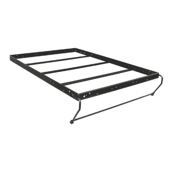
One universal bed frame for each of Single, Double, or Queen wall beds.
May be mounted in either vertical or horizontal modes.
A lightweight, universal, structural steel bed frame with double overlap
steel stiffeners, completed with fold-away leg system. Designed to
exceed the strength of wood or aluminium as well as residential and
info@wallbedsonline.co.nz
SINGLE
DOUBLE
QUEEN
KING
commercial specifications.
Designed to Exceed International ISO 9002
Standards for residential specifications
0800 WALL BEDS
HORIZONTAL:
(0800) 925 523)
SINGLE
DOUBLE
QUEEN
www.wallbedsonline.co.nz
Advertisement
Table of Contents

Related Manuals for Wallbeds alpha bed SBF


Summary of Contents for Wallbeds alpha bed SBF
- Page 1 VERTICAL: SINGLE HORIZONTAL: SINGLE DOUBLE DOUBLE QUEEN QUEEN KING One universal bed frame for each of Single, Double, or Queen wall beds. May be mounted in either vertical or horizontal modes. A lightweight, universal, structural steel bed frame with double overlap steel stiffeners, completed with fold-away leg system.
-
Page 2: Safety First
SAFETY FIRST Read the full instructions and familiarise yourself will all parts prior to assembly. Incorrect handling, assembly and installation of this product may result in personal injury or damage to property. Practice personal safety protection. Wear safety glasses, ear protection and closed in shoes as necessary while manufacturing cabinetry, assembling and installing this product and associated cabinetry. -
Page 3: Project Start-Up
PROJECT START-UP 1. Familiarise yourself with all components. Open up the Alpha Bed Steel Frame Box and the SBLM Mechanism Carton. Using this manual as a reference go through and identify each part and check off on list that everything is there. Study this manual thoroughly so you can plan the steps required to complete your project. - Page 4 CARTON CONTENTS FOR...
-
Page 5: Vertical Orientation
RAIL SET LAYOUT The frame is adaptable as vertical or horizontal (side tilt) bed and has mounting holes to connect with the SBLM Mechanism. VERTICAL ORIENTATION: Drawing One HORIZONTAL (SIDE TILT) ORIENTATION:* Drawing Two * Longer Leg Bar for Horizontal Orientation available to purchase on request. - Page 6 CABINET CUT LIST VERTICAL ORIENTATION Following are guidelines for cabinetry panel work. Customers decision to modify these guidelines will be at customers own risk. All drilling directions for the mechanism should not be modified. Please Note: All dimensions stated are finished dimensions and as such include tape. SINGLE BED Overall Cabinet Dimensions: 1130mm wide x 406mm deep x 2115mm high...
- Page 7 CABINET CUT LIST VERTICAL ORIENTATION - continued KING BED Overall Cabinet Dimensions: 2070mm wide x 406mm deep x 2242mm high Mattress Dimensions: Depth from wall when open: 2286mm 1930mm wide x 2032mm long x 305mm thick Cabinet Material: 18mm MDF or Plycore QUANTITY DESCRIPTION WIDTH mm...
-
Page 8: Horizontal Orientation
CABINET CUT LIST HORIZONTAL ORIENTATION SINGLE BED - SIDE TILT Overall Cabinet Dimensions: 2032mm wide x 406mm deep x 1264mm high Mattress Dimensions: Depth from wall when open: 1245mm 990mm wide x 1905mm long x 305mm thick Cabinet Material: 18mm MDF or Plycore LENGTH QUANTITY DESCRIPTION... - Page 9 CABINET CUT LIST HORIZONTAL ORIENTATION - continued QUEEN BED - SIDE TILT Overall Cabinet Dimensions: 2159mm wide x 406mm deep x 1797mm high Mattress Dimensions: Depth from wall when open: 1778mm 1524mm wide x 2032mm long x 305mm thick Cabinet Material: 18mm MDF or Plycore LENGTH QUANTITY DESCRIPTION...
- Page 10 STEP BY STEP INSTRUCTIONS Please make sure to read each step in full before attempting to complete that step. STEP ONE Prepare all cabinetry panel work components. Use the previous Cut List guidelines to prepare your cabinetry panel work. Customers decision to modify these guidelines will be at customers own risk. All drilling directions for the mechanism should not be modified.
- Page 11 DRILLING FOR MECHANISM 406mm 59mm 300mm 446mm 410mm 454mm 367mm 279mm Toe Kick Drawing Four...
- Page 12 STEP THREE Install the springs on the Lift Mechanisms SPRING APPLICATION CHART Please Note: These are recommendations only. Actual number of springs required will depend on the total weight of the bed-face unit including the mattress and all bedding. BED PANEL MATERIAL BED SIZE PLYWOOD CORE PARTICLE BOARD...
- Page 13 STEP FOUR (VERTICAL) Assemble the Bed Cabinet (Vertical Orientation) Please refer to page 15 for Horizontal (Side Tilt) Diagrams If possible, the Bed Cabinet should be assembled in the room where it will be used. Be sure Lift Mechanisms are securely installed. 1.
- Page 14 STEP FOUR (VERTICAL) - continued 25mm 32mm 25x25x44mm Drawing Eight NOTE: There is an 11” (279) Leg option available. If using 11” (279) Legs adjust cabinetry panels as follows: 25x25x44mm Toe Kick Panel 51mm High Top Facia Panel 102mm High 76mm 508mm 25x25x44mm...
- Page 15 STEP FOUR (HORIZONTAL) Assemble the Bed Cabinet (Horizontal Orientation) Refer to the Horizontal Cut Lists on pages 8 & 9 for the corresponding panel descriptions that relate to the numbers in these images. Drawing Nine 25mm 25mm 25mm It is recommended to reinforce the vertical seam where the face panels meet with a 18x76mm wood...
- Page 16 STEP FIVE Attach Bed Cabinetry Securely to Wall. Hints: If the room is carpeted you may raise the toe kick up to 7mm to clear the carpet. More than 7mm will obstruct the operation of the bed. You may or may not wish to remove the Base Board to allow the Bed Cabinet to fit flush against the wall.
- Page 17 STEP SIX Assemble Steel Bed Frame to Face Panels Drawing Eleven (plan view) 25mm 25mm Drawing Twelve (side elevation view)
- Page 18 STEP SIX - continued 1. Lay the Bed Face Panels down on a non-scratch surface such as a carpet or blanket. 2. Completely assemble the 4 Frame Sections with the corner brackets and the 3/16”x1/2” (M5x12mm) black bolts provided. Refer to Drawing Twelve to properly place the leg stops at outer right and left bottom holes at the foot of the bed frame.
- Page 19 STEP SEVEN Set the Lift Mechanism If possible have a helper assist in the setting of the mechanism and loading of the bed face panel. DO NOT reach behind the tension arm when you are doing the setting procedure. Holding one foot against the bottom front edge of the side panel and using the 368mm leverage tube, lever the tension arm out until you can set the arm lock to the hex nut at the hole A (see Drawing...
- Page 20 STEP EIGHT Install the Bed Face Panel Unit 1. Insert Allen Head Bolts through Hole #1 (6 3/4” (171mm) from end of side frame) on both left and right side frames (see Drawing Fourteen). Thread on 5/16” (8mm) Nylock nuts and securely tighten. 2.
- Page 21 STEP NINE Install Handles - Legs - Mechanism Covers - Mattress 1. Position and secure handles for ease of operation. Measure down approximately 914mm from the panel top to the top of the handles. 2. Install legs with the washers on the inside of the Rails and the Nylon washer on the outside.
- Page 22 STEP TEN Complete Bed Assembly Check that the Bed Cabinet is level and square so the Bed Face has equal clearance of the Cabinet on both sides, top to bottom. If the Cabinet is leaning to one side, nudge it at the floor level. If the top is uneven, place shims under the Side Panels.
Need help?
Do you have a question about the alpha bed SBF and is the answer not in the manual?
Questions and answers