Table of Contents
Advertisement
Quick Links
Advertisement
Table of Contents

Related Manuals for Powerlink GXE350-NG


Summary of Contents for Powerlink GXE350-NG
- Page 1 GAS GENERATOR SET GXE350-NG OPERATION MANUAL www.powerlinkworld.com...
-
Page 3: Table Of Contents
Natural Gas Unit TABLE OF CONTENTS Preface ..............4 1. Safety Information ............5 1.1 Safety Instruction ....................... 5 1.2 Safety Knowledge about Natural Gas ................. 6 1.2.1 Brief Introduction to Natural Gas ................6 1.2.2 Features of Natural Gas ................... 6 1.3Safe Operation ........................ - Page 4 Natural Gas Unit 5. Operation for GCC-742 Control System ........34 5.1Control Cabinet ......................... 34 5.2 Control Module ........................ 35 5.3Working State Chart ......................36 5.3.1 Manual Operation State ..................36 5.3.2 Remote Operation Chart ..................37 5.3.3AMF Operation Chart ..................... 38 5.4 Operation Instruction ......................
- Page 5 Natural Gas Unit 7.8.1 Belts - Inspect/Adjust/Replace ................59 7.8.2 Alternator Pulley - Check ..................59 7.9 Battery Maintenance ......................59 7.9.1Battery cable disconnecting ..................60 7.9.2 Battery power checking ..................61 7.9.3 Battery charging ....................62 7.10 Lifting and transporting ....................63 7.11Overnight Storage ......................
-
Page 6: Preface
Natural Gas Unit Preface Dear customers: Thanks for selecting our company's gas genset. This installation and operation manual provides you such aspects of supporting and suggestions as genset's installation and operation to prevent accidents from happening and to assure that the validity of manufactures' warranty. In this way, we can assure you a durable and ready-to-use genset. -
Page 7: Safety Information
Natural Gas Unit 1. Safety Information 1.1 Safety Instruction Incorrect installation, operation and maintenance of electro-mechanical equipment such as genset, change-over switches, switching devices and accessories can lead tophysical injuries and even life danger. It's a necessity to know the potential danger and safety operation so as to avoid accidents. -
Page 8: Safety Knowledge About Natural Gas
Natural Gas Unit 1.2 Safety Knowledge about Natural Gas 1.2.1 Brief Introduction to Natural Gas Natural gas is the combustible gas formed from the palaeobios buried under the ground under the function of high temperature and high pressure for billions of years. It mainly exists in the oil field and natural gas field, with a small number of them existing in the coal bed. -
Page 9: Safe Operation
Natural Gas Unit 1.3Safe Operation Before the machine leaves the factory, the parameters have been adjusted according to the practical instance. The user needn't adjust personally. Modifying or resetting the parameter of controller must be permitted and operated by the equipment administrator or manufacturer authorized person. - Page 10 Natural Gas Unit Safety During Operation Do not allow any child or animal to access the operating area when the genset is working. Wear personal protective equipment such as gloves, work shoes, goggles and hearing protection. Do not touch any wire when the genset is running, because they are live and may cause electrical shock.
- Page 11 Natural Gas Unit eheat device. Otherwise, the preheater in intake manifold may explode and cause personal injury. Keep your hands and other body parts away from the hot surfaces such as the muffler, exhaust pipe, turbocharger (if equipped), engine block and alternator block during operation and shortly after you shut the engine down.
- Page 12 Natural Gas Unit...
-
Page 13: First Aid
Natural Gas Unit 1.4 First Aid... - Page 14 Natural Gas Unit...
- Page 15 Natural Gas Unit...
-
Page 16: Emergency Treatment For The Leakage Of Natural Gas
Natural Gas Unit 1.5 Emergency Treatment for the Leakage of Natural Gas When dealing with the leakage of natural gas, you should eliminate dangerous cases quickly and effectively in accordance with the features of leakage and combustion so as to avoid explosion and combustion. -
Page 17: Emergency Measures Intoxication And Suffocation Accidents For Natural Gas
Natural Gas Unit ⑤ If fire disaster has happened in the station, observe the following steps to conduct a preliminary control with the cooperation of professional firefighters: If it is for the reason of natural gas leaking, you should first find out the leaking point, and then close the upstream valve so as to stop the burning. - Page 18 Natural Gas Unit ④ The slightly poisoned ones can be sent to the near health station and health center to receive treatment. ⑤ The medium poisoned ones should be performed oxygen therapy with a resuscitator on the spot until their breathing and heartbeat turn normal. They can be sent to hospitals when they feel well.
-
Page 19: Significant Information
Natural Gas Unit 2. Significant Information 2.1 Delivery and Receiving Interior inspection when delivering includes examination whether all the components are at place. If the equipment is in damage or some components lose, then you should deal with this matter in accordance with the specifications in the delivery contract. -
Page 20: Genset Installation
Natural Gas Unit 3. Genset Installation 3.1 Installation Requirements of Gas Pipelines 3.1.1 Preparation before installation Conduct a interior cleaning of the pipeline parts. Construction Scheme should be approved before installation and the construction drawings, technical documents, components and tools should all ready. Furthermore, the design scheme, construction drawings and technical documents must meet the current national standard of <Gas Design Specifications in Cities and Towns>... -
Page 21: Indoor Installation Requirements
Natural Gas Unit they must be installed in their right direction. Units responsible for the pipeline construction in the machine room should possess the authorized quality of corresponding national departments and operational personnel engaged in pipeline construction must be trained foe professional skill and be qualified. 3.2 Indoor Installation Requirements 3.2.1 Room Requirements The lightning, vibration, ventilation, fire, lighting and environment protection factors should be... -
Page 22: Installation Location
Natural Gas Unit 3)Fire Protection The genset room should be provided with the fireextinguisher. The genset room should beprovided with automatic fire alarm system & automatic fireprotection system. 4) Noise Reduction The soundproof type generator set’s noiseachieves 65 to 85dBA @ 7m. Keep the gensetroom away from the place where needs quietas far as possible and recommend equippingthe room with noise insulation and absorptiondevices 3.2.2 Installation Location... -
Page 23: Mainsinputconnections
Natural Gas Unit 3.3 MainsInputConnections Mainscanprovidepowertocriticalcomponentsonthegeneratorset,likebatterycharger,coolantheater, oilheaterandotherdevices. Thestandardproductis equippedwithbatterychargerwhichislocatedintheelectriccomponentsbox.Thepowerofbattery will decreasewhilethebatteryisstoredornotrunningforalongtime.Tomaintainthegeneratorsetinagoodca pabilityofstarting,rechargeitonceamonthinsummer,andevery2monthsinwinter.Theusercancharget hebatterybyconnectingtheconnector(4or9pinwhicharementionedin)tothemains.Thechargeindicat orinthecontrolpanelwillilluminatewhenchargingandbeoffafterfinishinthecharge.Itisrecommendedt oequipappropriateheater(waterjacket heater,oilheaterorotherdevices)ontheengineforitishardtostartinthecoldenvironment.Theheatersta rtstoworkautomaticallywhenitpoweredbythemains.Whenthetemperaturereachesthepresetvalueor theenginehasstarted,theheaterunitwillstopworkingautomatically. Thestandardproductprovidesanadditionalmounthole(beblockedbyaplugifnotbeapplied)fortheheat ersconnectionwhichnearthe4or9pinconnector.Iftheheater(s)is or are)opted,a4pinconnectorwouldbemounted.Theusercanactivatetheheatingfunctionbyconnectingt heconnectortothemains. 3.4LoadsConnections 3.4.1 LoadCablesSelection Selectthecablewithproperdiameter,basedonitsallowableamperageandthedistancebetweenthege nsetandtheload.Thereismaximum5%marginaldroponlyfotheratedvoltagebetweentheterminalsoflo adsandgensetviathecables.Itshouldbeconsideredwhileselectingthecable. Danger: If load exceeds allowable amperage, the cablemay be damaged for over- heating. ... -
Page 24: Loads Connections
Natural Gas Unit 3.4.2 Loads Connections STOP THE GENSET FIRST!! Loads can be connected to the generator by thePower Ouput Terminals or the convenience receptacles.Make sure to read the operation manual andswitch ALL circuit breakers to the OFF position beforeattempting to connect a load to the generator. -
Page 25: Batteryconnections
Natural Gas Unit 3.5 BatteryConnections 3.6 Gas Connection Genset uses gas pipelines to supply fuels. Gas jointis set on the side face of genset's cabinets. When connecting gas, you just need to connect the joint of the gas supply pipelines in the machine room and that of the genset's gas with a hosepipe. - Page 26 Natural Gas Unit ④ Use a hosepipe to connect the gas supply pipeline and the gas joint of the genset (The position of the genset's gas joint is as the following figure); ⑤ Check the gas valve bank to make sure that cut-off ball valve (See the below figure) is at closed state;...
- Page 27 Natural Gas Unit ⑥ Open the main valve of the gas supply pipeline and use gas leakage detector to check whether the connecting point leaks or not. Warning: Only professional staff can connect the gas intake flange. The main valve of gas pipeline and the cut-off ball valve of genset must be closed before connecting.
-
Page 28: Introduction To Genset
Natural Gas Unit 4.Introduction to Genset 4.1 Applications and Features 4.1.1 Applications Generator set is one type of AC power supply equipment, which is driven by diesel engine that drives the synchronous alternator to generate electricity. The genset is used as a power source for three main types of services as follows: (1) Continuous service Used as a main power to not only provide daily power for families, enterprises, governments etc. -
Page 29: An Overview Of Genset's Operational Flow Chart
4.3Genset Performance Data 1) Performance data and manufacturing technology Genset performance data and manufacturing technology Telephoneinterference ≤50 Genset model GXE350-NG factor(TIF) ≤2% , as per Telephone harmonious Electrical output power (kW) BS4999 factor(THF) Genset electrical efficiency 38.8 %... - Page 30 Natural Gas Unit 3) Structure and control cabinet Structure Open type Canopy painting High-class paint Electrical control cabinet Integrated, IP54 <75.2 Noise level@7m,dB(A) 4) Dimension and weight Dimension (LxWxH), mm 4900×1720×2500 Weight, kg 5042 5)Fuel and emission Fuel type Natural gas MN ≥80 Methane number Excess air factor(Lambda)...
-
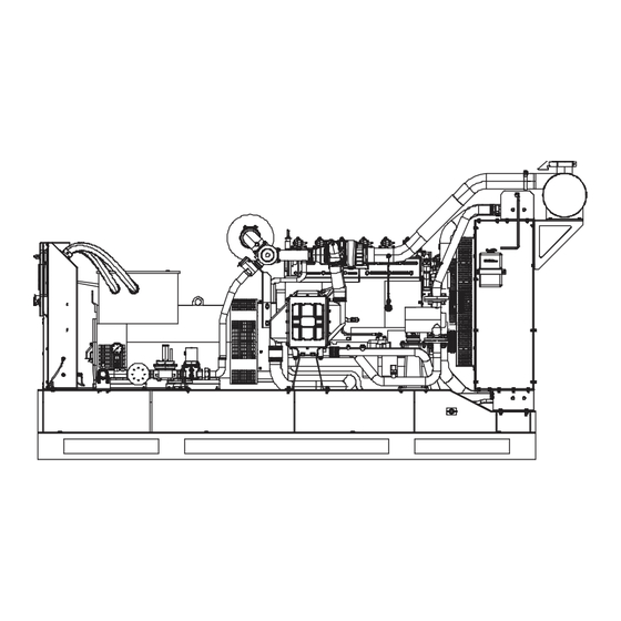
Page 31: Overview Of Genset's Structure
Natural Gas Unit 4.4Overview of Genset's Structure Gas genset is a kind of small-scale power generation equipment and drive the generator to generate power, with natural gas being fuel and gas engine being the motive power. A genset generally consists of a gas engine, a alternator (Power ball) and a control system and also includes a control panel, a switch cabinet, a radiator, a gas supply system, startup and control storage batteries, protective equipment, a lighting system, muffler and a common base. -
Page 32: Introduction To Genset's Main Systems
As the engine part of genset, gas engine mainly includes a gas system, a cooling system, performance data alubricating system and an ignition system. Its is as following. Gas engine Brand PowerLink Model GX12T-LE02G NO. of cylinders In line Cylinders arrangement... -
Page 33: 2Alternator
Alternators used in our company are of excellent performance and reliable safety. Alternators and engines constitute genset's power pack and their definite connecting method is as the following figure: AC alternator Brand Powerlink Model PL5S Rated output power @400V (kW) Power factor... -
Page 34: Gas Supply System
Natural Gas Unit 4.5.3 Gas supply system The gas supply systeminclude gas safetytrain,air/fuel mixer and throttle valve, whichconnect the gas supply pipeline and the gas inlet of the genset. 4.5.4 Battery's Components The direct current system of a engine includes a startup motor and two 12 V batteries and chargers. -
Page 35: Control System
Natural Gas Unit 4.5.5 Control System The gas genset adopts GCC-742 control system, which with all necessary functions to protect and control the gas genset. -
Page 36: Operation For Gcc-742 Control System
Natural Gas Unit 5. Operation for GCC-742 Control System GCC-742 is an advanced control module based on microprocessor,containing all necessary functions for protectionof the genset and the breaker control. It can monitor themains supply, and automatically start the engine when themains is abnormal. Accurately measure various operationalparameters and display all values and alarms information onthe LCD. -
Page 37: Control Module
Natural Gas Unit 5.2 Control Module... -
Page 38: Working State Chart
Natural Gas Unit 5.3Working State Chart 5.3.1 Manual Operation State... -
Page 39: Remote Operation Chart
Natural Gas Unit 5.3.2 Remote Operation Chart... -
Page 40: 3Amf Operation Chart
Natural Gas Unit 5.3.3AMF Operation Chart... -
Page 41: Operation Instruction
Natural Gas Unit 5.4 Operation Instruction 5.4.1Manual Operation (1) Start ① Shut off every switch and circuit breaker of loads. ② Shut off the Genset Main Circuit Breaker (GB)and other circuit breakers. ③ Open the main valve of the gas supply pipelineand turn on the cut-off ball valve of gas train. -
Page 42: 2Remote Operation
Natural Gas Unit 5.4.2Remote Operation The genset can be set remote control function.Connecting to the remote control switch by 9 or 4 pin communication connector realizes remote startand stop. NOTE: Remote start and AMF functions can onlybe applied separately. Setting remote control switch ①... - Page 43 Natural Gas Unit Operation Instruction (1) Start ① Press the Remote Start Button. ② When the control module receives remote startsignal, it will perform the auto start sequence. ③ After the genset starts successfully, switch on everyswitch of loads (from heavy to low in sequence).The genset will export power to load.
-
Page 44: Amf Operation
Natural Gas Unit 5.4.3 AMF Operation GCC-742 control system has AMF function. It is able to realize to start and stop the genset automatically by connecting 9 pin communication connector to the mains, and transfer automatically the power supply of loads between the mains and genset by the control of genset's motor main circuit breaker (if applied). -
Page 45: Protection Function
Natural Gas Unit 5.5 Protection Function Warning: Refer to troubleshooting guidelines in this manualto repair the machine and remove the fault. ContactPOWERLINK or our authorized distributor forhelp if you could not deal with it. The poisoned ones should be kept warm during the whole emergency treatment process. -
Page 46: Parameter Configuring
Natural Gas Unit 5.6Parameter Configuring Although full configuration of the module is possibleusing configuration software, selected parametersthat may require adjustment in the field are able tobe adjusted via the module's fascia. ① Ensure the engine is at rest and the module is inSTOP mode by pressing the Stop Button. -
Page 47: Genset's Operation
Natural Gas Unit 6.Genset's Operation 6.1 Pre-Check Before Starting 6.1.1General Pre-check... -
Page 48: 2Checking Engine Oil Level
Natural Gas Unit 6.1.2Checking Engine Oil Level 1)Checking oil level of engine ① Open the access door( if the genset is soundproof canopy ). ② Make sure the engine is level. ③ Take out oil gauge and wipe it with a clean cloth. ④... -
Page 49: 3Checking Coolant Level
Natural Gas Unit 6.1.3Checking Coolant Level... -
Page 50: Check The Intake System
Natural Gas Unit 6.1.4 Check the Intake System 1) Check Gas Intake Pressure Before set the pressure regulator, it's a must to check the gas supply pressure to assure that the pressure is between 5kpa to 25kpa. 2)Check gas pipelines Check whether the air intake system has the following circumstances: ... -
Page 51: Check The Hosepipe And Hoop Iron
Natural Gas Unit As for pipelines that cannot be tested for the moment, they should be indicated in the record and attached with figures. Furthermore, they should be reported to a higher body in time. When spotting the leakage accident, first of all you should exclude the illusory vision, such as peculiar smell from the rotten animals and plants and odor from other equipment;... - Page 52 Natural Gas Unit Whether the flexible part of hosepipe twists up or squeeze out. 2) Replace the Hosepipe and Hoop Iron It's recommended to use hosepipe and hoop iron with constant torque to replace that of any standard so as to assure that the size of hosepipe and hoop iron with constant torque is the same with that of the standardized ones.
-
Page 53: 6Checking Battery Coulomb
Natural Gas Unit 6.1.6Checking Battery Coulomb... -
Page 54: Starting Up Genset
Natural Gas Unit 6.2 Starting up Genset 6.2.1 Manual Operation You can operate genset manually when operating locally. Start up genset , switch on, connect to grid and load after opening the gas cut-off ball valve, negative switch of storage battery, and Refer to detailed flow chart . - Page 55 Natural Gas Unit Notice: When the emergency shutdown button is pressed, genset will shut down andthe button will be kept in the inside position. Before starting up the engine, youneed to rotate this button so that it can automatically pop up and reset, or it cannot start up.
-
Page 56: Maintenance
Natural Gas Unit 7.Maintenance 7.1General Maintenance should be performed by a licensedengineer. For detailed maintenance procedures on theengine or alternator, refer to their own operationmanual. Prior to starting any maintenance work, alwaysstop the machine as described in these operatinginstructions prior to removing any safety claddingor safety devices. -
Page 57: Generator Set Maintenance
Natural Gas Unit 7.3Generator Set Maintenance Inspect the genset daily or after every eight hourof operation, whichever comes first. Check the mechanical,exhaust, fuel, and DC electrical systems. 7.3.1Mechanical System Inspect any signs of mechanical damage. Start the genset and listen for any unusual noise, which may indicate mechanical problems. -
Page 58: 3Gas System
Natural Gas Unit 7.3.3Gas System Start the genset, inspect the gas supply system: Check pipeline and all the valve , make sure that there is no gas leakage. Inspect all flexible sections for cuts, cracks and abrasions. Make sure that the gas pipeline do not rubagainst anything that could break them. -
Page 59: Air Cleaner Element -Replace
Natural Gas Unit 7.4.2 Air Cleaner Element –Replace ① Remove the retaining clips (3). Remove the cover(4). ② Remove the old element (2). Dispose of the old element. ③ Install a new element into the air filter housing (1). Install the cover (4). Fit the retaining clips (3). Warning: ... -
Page 60: Engine Oil And Oil Filter
Natural Gas Unit 7.6 Engine Oil and Oil Filter 7.6.1Change Engine Oil ① Remove the oil drain plug on the side of thebase frame. ② Turn on the oil pump ball valve which is underthe oil pan or oil pump. ③... -
Page 61: Alternator - Inspect
Natural Gas Unit 7.8 Alternator – Inspect Powerlink recommends a scheduled inspection of the alternator: Inspect the alternator for loose connections and correct battery charging. Check theammeter (if equipped) during engine operation inorder to ensure correct battery performance and/orcorrect performance of the electrical system. -
Page 62: 1Battery Cable Disconnecting
Natural Gas Unit 7.9.1Battery cable disconnecting Always be sure the battery cables are properly connected to the battery terminals as shown below. The Red Cable is connected to the positive terminal of the battery, and the Black Cable is connected to the negative terminal of the battery. -
Page 63: Battery Power Checking
Natural Gas Unit 7.9.2 Battery power checking POWERLINK adopts maintenance free battery. So it is not necessary to add distilled water or electrolyte, only check the coulomb periodically. -
Page 64: Battery Charging
Natural Gas Unit 7.9.3 Battery charging... -
Page 65: Lifting And Transporting
Natural Gas Unit 7.10 Lifting and transporting The base frame of the genset has four lifting lugs. Refer to the Technical Data for the weight of the genset. Make sure the lifting devices have enough capacity to lift the unit safely. TRANSPORT Warning: ... -
Page 66: Overnight Storage
Natural Gas Unit 7.11Overnight Storage Proper operation is essential for preserving top genset performance and reliability when storing the genset overnight. Check and make sure the engine battery switchand all genset circuit breakers are placed “OFF”position. Make sure that the control cabinet and accessdoors((if equipped)) are closed and padlocked.
Need help?
Do you have a question about the GXE350-NG and is the answer not in the manual?
Questions and answers