Table of Contents
Advertisement
Quick Links
Advertisement
Table of Contents

Subscribe to Our Youtube Channel
Related Manuals for Noraxon Core EMG


Summary of Contents for Noraxon Core EMG
- Page 1 Core EMG Hardware User Manual Hardware User Manual (Rev D)
-
Page 2: Table Of Contents
Basic Operation Instructions .......................... 17 Safety Information Summary ....................... 17 Operating Environment .......................... 17 Ensure the Core EMG Sensor is in Measurement Mode ..............18 Attach the Core EMG Sensor to a Patient or Subject............... 19 Configure a Measurement ........................19 Enter the Measurement Screen ...................... - Page 3 Appendix B – Use of Disposable Electrodes ..................36 13.3 Appendix C – Radiation Exposure Information Regarding Use of EMG Sensors ....... 37 13.4 Appendix D – Radio Regulatory Statements ..................38 13.5 Appendix E – Core EMG LED Status Guide ..................39 (Rev D)
-
Page 4: Authorized European Representative
Noraxon and myoRESEARCH are registered trademarks and the Noraxon logo, myoANALOG, myoFORCE, myoMETRICS, myoMOTION, myoMUSCLE, myoPRESSURE, myoVIDEO, myoSYNC, NiNOX, TRUsync and Ultium are common-law trademarks of Noraxon U.S.A., Inc. All other trademarks are the property of their respective owners. ©2018, all rights reserved. -
Page 5: General Warnings And Cautions
1.1 Risks and Benefits There is no identified risk of physical harm or injury with use of the Core EMG System. The benefit provided by use of the device is the provision of objective measures to assess the severity of pathological human movement conditions and gauge any subsequent improvement offered by therapy, training, or design changes. - Page 6 Core EMG Hardware User Manual Guidance on Conditions for Safe Use The Core EMG sensors are suitable for use as medical devices. To ensure safe operation the following guidelines must be strictly followed. The Core Hub and computer must not be accessible (touchable) by the patient. Ensure the ●...
-
Page 7: Introduction
This concept gives the user the flexibility to operate the Core EMG System through a streamlined data collection process and without the traditional laboratory-based measurement limitations. The small, lightweight EMG sensors are also beneficial for small subjects like children and small animals. -
Page 8: Intended Use
EMG System may exhibit sluggish (non-real time) behavior. Risk-Benefit There is no identified risk of physical harm or injury with the use of the Core EMG product. The benefit provided by use of the device is the provision of objective measures to assess the severity of pathological human movement conditions and gauge any subsequent improvement offered by therapy, training, or design changes. -
Page 9: Definitions
3 Definitions 3.1 Graphic Symbols and Meaning The following international icons and symbols are found on the Core EMG enclosures and in this user manual. Their meaning is described below. Approval to market this product (#810) in the European Community was certified by Notified Body #2797 BSI. -
Page 10: Glossary Of Terms
2.4 GHz unlicensed radio band to interconnect nearby devices. RF Network – RF transmissions for the Core EMG System can be selected to occur on one of 4 different networks. All networks use frequency hopping to avoid interference. -
Page 11: Product Information
5 Setting up the Hardware 5.1 System Unboxing The Core EMG System is packed within a reinforced padded box for storage and protection during transport. Upon receiving the package, carefully remove all contents and verify the following components are present. -
Page 12: Core Hub Overview
Core EMG Hardware User Manual 5.2 Core Hub Overview Hub (Front/Top) Hub (Back) 1. Status LED – Indicates the status of the hub. 1. Sync Port – TTL (on-off) compatible 3.5 mm audio jack connection to other 2. OFF/ON Power Buttons – Sends Power OFF devices. -
Page 13: Core Emg Sensor Overview
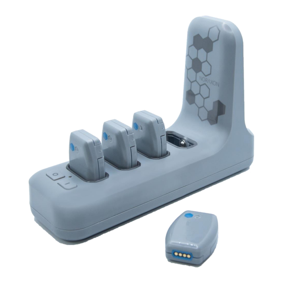
Core EMG Hardware User Manual 5.3 Core EMG Sensor Overview EMG Sensor (Front/Bottom) EMG Sensor (Back/Bottom) 1. Power Button – Power the sensor 1. Electrode Snaps – Third electrode that On/Off. Hold for 3+ seconds for a provides a ground reference for the differential hard reset. -
Page 14: Hardware Setup Instructions
Insert the Core EMG Sensors (#816) into the Hub. 5.5 Installing the Companion Software – myoRESEARCH™ 3 To utilize the full functionality of the Core EMG system, and ensure the system has updated drivers, myoRESEARCH 3 Noraxon’s needs to be installed on the computer. -
Page 15: Configuring The Hardware
Activation Code. 5.6 Configuring the Hardware Before the Core EMG System can be used, the device software settings must be configured to recognize the components that make up the system. Follow the instructions below to detect sensors, setup sync, and update sensor or hub firmware in preparation for data collection. - Page 16 Core EMG Hardware User Manual Step 3 The Core EMG Settings dialog will appear as shown. With the Core EMG Sensors inserted into the slots on the Hub, click Detect Sensors in Charger to load all serial numbers into the MR3 software.
-
Page 17: Basic Operation Instructions
3. MyoMuscle – One of the software modules running under MR3 that is specific to EMG devices such as the Core EMG System The Core EMG System (a member of the Ultium product family) acquires EMG signals from the patient via EMG sensors (the medical device) which wirelessly transmit the measured signals to any receiver that is part of the Ultium product family. -
Page 18: Ensure The Core Emg Sensor Is In Measurement Mode
Noraxon. These specifications are subject to change without notice due to the volatility of the computer industry. It may be assumed that systems shipped by Noraxon will meet or exceed these specifications. Systems quoted with these specifications are good for three months after the date of the quotation. -
Page 19: Attach The Core Emg Sensor To A Patient Or Subject
EMG signal exhibits a wandering baseline. (See Appendix A) Note: The Core EMG Sensor is designed for use with the dual EMG electrodes provided by Noraxon with the standardized 20 mm inter-electrode spacing. -
Page 20: Enter The Measurement Screen
USB ports. 6.7 Check for Normal Signal Display with Interface to a PC When used with the companion software, the Core EMG System displays and records raw (or processed) EMG waveforms, like the waveform displayed below. -
Page 21: Check Signal Quality
Within the Noraxon myoRESEARCH platform, standard procedures and best practice functionality has been built in to assist the practitioner with identifying their current signal quality. With the Core EMG system, a live signal status monitor provides real-time information for practitioners to understand the current recording conditions. -
Page 22: Record Signal As Desired
6.8.6 Related Software Measurement Tools Within the Noraxon myoRESEARCH software is a suite of tools that can be used during EMG measurements. Below is a list of the most used features for electromyographic recordings. Additional information around more advanced features can be found on www.noraxon.com... -
Page 23: Additional Core Emg Settings And Features
Core EMG Hardware User Manual 7 Additional Core EMG Settings and Features 7.1 Core Hub Synchronization To synchronize the signal(s) from the Core EMG System with other devices, it is necessary to configure the hardware and software to accept an incoming sync signal. 7.1.1 Sync In Port The Sync In port on the back of the Hub is designed to accept a 2-5 V TTL sync input via 3.5 mm audio... -
Page 24: Lossless Data Recovery
Core EMG Hardware User Manual 7.2 Lossless Data Recovery The Core EMG System supports “lossless” data recovery. The sensors continue to capture and store data (>8 hours of data) when communication is temporarily lost with the Hub. Once the record is completed, data can be recovered in real-time or later using the import function. -
Page 25: Maintenance
Dual solid gel EMG electrodes (30 per pouch or 210 per box) 8.2 Maintenance by Users Routine maintenance is recommended for the Core EMG system for successful performance. Cleaning and charging the EMG sensors regularly will help preserve long-term operation. 8.2.1 Charging the EMG Sensors Note: No safety precautions are required for charging the EMG sensors. -
Page 26: Companion Software Updates
Cleaning The EMG Sensors For sanitary purposes, it is advisable to clean the Core EMG Sensors on a regular basis. The Core EMG Sensors can be cleaned with a cloth slightly dampened with a solution of mild soap and water or disinfectant solution (i.e., isopropyl alcohol swabs or non-bleach disinfectant wipes). -
Page 27: Battery Replacement
8.5.1 Battery Life Expectations The Lithium Ion coin cell battery used in the Core EMG sensors is rated for a minimum of 300 charge- discharge cycles. Typical usage is 500 charge-discharge cycles. As the number of charge-discharge cycles increases the battery capacity slowly declines thereby reducing run time despite being fully charged. -
Page 28: Website Link To Faq
WiFi enabled devices. Despite all this competing radio activity the Core EMG System can discern its information from all the surrounding radio traffic. Reliable transmission depends on good signal quality. Signal quality will fall with extended distances between the Hub and the EMG Sensors. -
Page 29: Support, Service, And Repair
11 Taking Product out of Operation 11.1 Disposal of Equipment and Batteries The Core EMG Sensors contain Li-Ion coin cell batteries, which may be hazardous if disposed of incorrectly. Please check with the governing authorities in your location before disposing of the Core EMG System and its contents. -
Page 30: Technical Information
12.1 Theory of Operation The Core EMG wireless system is based on a pre-certified transceiver module. This radio module operates in the 2.4 GHz bands with an output power level of < 100 mW and is based on a proprietary frequency hopping protocol. -
Page 31: Electro-Magnetic Compatibility Tables
Guidance and manufacturer’s declaration – electromagnetic emissions The Core EMG System is intended for use in electromagnetic environment specified below. The customer or the user of the Core EMG System should assure that it is used in such an environment. - Page 32 Guidance and manufacturer’s declaration – electromagnetic immunity The Core EMG System is intended for use in electromagnetic environment specified below. The customer or the user of the Core EMG System should assure that it is used in such an environment.
- Page 33 Core EMG System The Core EMG System is intended for use in an electromagnetic environment in which radiated RF disturbances are controlled. The customer or the user of the Core EMG System can help prevent electromagnetic interference by maintaining a minimum distance between portable and mobile RF communications equipment (transmitters) and the Core EMG System as recommended below, according to the maximum output power of the communications equipment.
-
Page 34: Appendices
13.1 Appendix A – Product Specifications Expected Useful Lifetime Both the Core Hub (#884) and Core EMG Sensor (#816) have a usable life of seven years. The EMG sensors (#816) operate with a rechargeable Lithium-Ion coin cell battery. The battery capacity will decline with ongoing use and require replacement after 300+ discharge/charge cycles to preserve the device’s rated 4 hours of operating time. - Page 35 Core EMG Hardware User Manual Performance Characteristics Output & Transmission Frequency (Depending on country) Up to 100 mW (depending on country allowance) ● ● GFSK 2402-2480 MHz, frequency hopping Utilizing up to 79 hopping channels ● Channel-to-channel hopping frequency 50 Hz (20 msec) ●...
-
Page 36: Appendix B - Use Of Disposable Electrodes
EMG signal may be affected. Also, sometimes the electrode adhesive may not adhere to the skin as well when it is reapplied. Noraxon strongly recommends against the use of dried out electrodes that are re-wetted with electrode gel. -
Page 37: Appendix C - Radiation Exposure Information Regarding Use Of Emg Sensors
(next to the person’s head). At present, Noraxon identifies no restrictions on use and placement of the EMG sensors on any portion of the human body. The EMG sensors operate at radio frequencies known to affect older style pacemakers. -
Page 38: Appendix D - Radio Regulatory Statements
Core EMG Hardware User Manual 13.4 Appendix D – Radio Regulatory Statements FCC Statement This device complies with part 15 of the FCC rules. Operation is subject to the following two conditions: (1) This device may not cause harmful interference, and (2) this device must accept any interference received, including interference that may cause undesired operation. -
Page 39: Appendix E - Core Emg Led Status Guide
13.5 Appendix E – Core EMG LED Status Guide The Core EMG sensor and Core Hub have an LED indicator which displays the status of the sensor and hub. Please reference the following list for information on what each LED status means. - Page 40 Core EMG Hardware User Manual (Rev D)
Need help?
Do you have a question about the Core EMG and is the answer not in the manual?
Questions and answers