Table of Contents
Advertisement
Quick Links
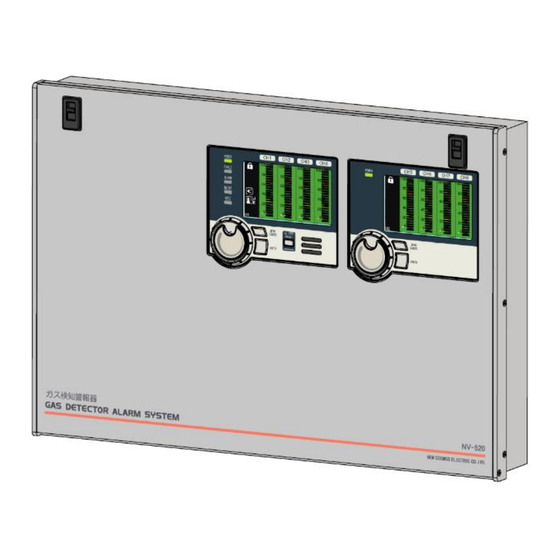
Multi-Channel Gas Alarm System
NV-520
Instruction Manual for Installation
Keep this manual for easy reference.
Prior to use, carefully read this manual as well as the NV-520 instruction manual for operation (separate
document) for correct use.
This manual describes the standard model. If your unit has end-user-specific options, this manual will
be superseded by your delivery specifications.
Instruction Manual No.
GAE-174-00
July 2023
Advertisement
Table of Contents

Related Manuals for New Cosmos Electric NV-520


Summary of Contents for New Cosmos Electric NV-520
- Page 1 Instruction Manual for Installation Keep this manual for easy reference. Prior to use, carefully read this manual as well as the NV-520 instruction manual for operation (separate document) for correct use. This manual describes the standard model. If your unit has end-user-specific options, this manual will be superseded by your delivery specifications.
-
Page 2: Related Manuals
Related Manuals The following documents have been prepared to guide your installation and use of this product. (1) NV-520 Instruction Manual for Installation (this document), No. GAE-174-xx This document is intended for supervisors and service personnel who are concerned with the installation of this product. -
Page 3: Introduction
Thank you for purchasing the New Cosmos NV-520 multi-channel gas alarm system (“product” or “unit” hereafter). Prior to use, please read this manual as well as the NV-520 instruction manual for operation (No. GAE-175-xx) and follow the instructions provided for the correct use of the product. - Page 4 This manual uses Danger, Warning, Caution and Notice symbols to draw attention to procedures, materials, methods and processes that require particular attention. Indicates an imminently hazardous situation that can result in death or serious injury. Indicates a potentially hazardous situation that may result in death or serious injury. Indicates a hazardous situation that may result in minor injury or property damage.
-
Page 5: Quick Index
Quick Index This page lists parts that may be often referenced throughout the document. Prior to use, please read the precautions in 1 “General Precautions”. Unit Dimensions and Components Pages 8 to 14 Installation Pages 18 to 24 M6x20 mounting screws M6x20 mounting screws Wiring and Connection Pages 25 to 34... -
Page 6: Table Of Contents
Table of Contents Related Manuals ............................i Introduction ............................... ii Precautions ............................ii Symbols Used in this Instruction Manual ..................ii Quick Index .............................. iv General Precautions ......................... 1 1.1 Before Work ..........................1 1.2 Safety Precautions ........................1 1.3 Labels Affixed to Product ......................2 1.4 Disposal ............................ - Page 7 (This page intentionally left blank)...
-
Page 8: General Precautions
1 General Precautions General Precautions 1.1 Before Work To ensure safe use of the product and prevent unexpected accidents, please read the precautions in this manual carefully before turning on this product. New Cosmos is not responsible for any accidents resulting from any usage other than that outlined in this document. -
Page 9: Labels Affixed To Product
1 General Precautions 1.3 Labels Affixed to Product Warning and Caution labels are affixed to the areas or surrounding parts that are potentially dangerous and require special attention. Please read the contents of the labels carefully prior to use. Do not relocate the labels affixed to the product. If Warning and Caution labels are missing, damaged or illegible, please contact New Cosmos or its authorized representative for replacement or new labels. -
Page 10: Disposal
The service life of this product is 10 years. The unit can operate for up to 10 years with standard installation and operation in accordance with the NV-520 instruction manuals for installation and operation. When the service life has expired, replacement is essential for continued reliable performance and other purposes. -
Page 11: Batteries (For Backup Power Type Only)
1 General Precautions 1.7 Batteries (for Backup Power Type Only) This product uses two lead storage batteries. The batteries need to be replaced periodically. The replacement cycle changes depending on the frequency of use and environmental conditions. Follow the precautions listed below for proper operation. Batteries may short-circuit, resulting in electric shock or burns. -
Page 12: Battery Location
1 General Precautions 1.7.1 Battery Location Item Description Lead storage battery x 2 pcs 1.7.2 Battery Life If this product is to be kept unused or stored for an extended period of time, the batteries must be removed. Leaving the batteries inside while the product is not in use or being stored for an extended period of time may impair/reduce the performance/life of the batteries and cause their terminal corrosion. -
Page 13: Battery Disposal
1 General Precautions 1.7.3 Battery Disposal Used batteries must be disposed of as hazardous waste in accordance with the applicable laws and regulations. The Waste Electrical and Electronic Equipment (WEEE) directive (2012/19/EU) is intended to promote recycling of electrical and electronic equipment and their components at end of life. -
Page 14: Unit Structure
Panel-mounting kit Used to attach the brackets to NV-520 unit Tension screws (M6 x 40) x 4 pcs Used to attach the NV-520 unit to the panel Hex wrench set Used to install a gas detector Testing connector (test jig) -
Page 15: Unit Dimensions And Components
2 Unit Structure 2.2 Unit Dimensions and Components 2.2.1 External Appearance Refer to 15 “Specifications” of NV-520 Instruction Manual for Operation for the width Front View Side View (Dimensions are in mm) Bottom View 2-channel 2-channel 6-channel 10-channel without with backup power,... -
Page 16: Main Unit And Subunits
2 Unit Structure 2.2.2 Main Unit and Subunits It is possible to create a gas alarm system with up to 12 detection points using a combination of the Main Unit (U1) and Subunits (U2/U3). U1 displays gas concentrations sent via Channels 1 to 4, U2 displays gas concentrations sent via Channels 5 to 8, and U3 displays gas concentrations sent via Channels 9 to 12, in bar graph form. -
Page 17: Internal Appearance
2 Unit Structure 2.2.3 Internal Appearance ㉑ Channel LEDs (e.g., CH1-CH4) ⑳ CH.SWITCH button Item Component Description ZERO button Press and hold to enter the one-touch zero adjustment mode. SPAN button Press and hold to enter the one-touch span adjustment mode. TEST button Press and hold to enter test mode. -
Page 18: Collective Terminal Block
2 Unit Structure 2.2.4 Collective Terminal Block Terminal Function AC Type 1st stage gas alarm 1st stage gas contact output alarm Common with A1 2nd stage gas alarm 2nd stage gas contact output alarm Common with A2 (Thread size: M3) Audio alarm contact output DC Type Audio alarm... -
Page 19: Home Screen (Gas-Monitoring Screen)
3 HOME Screen (Gas-Monitoring Screen) HOME Screen (Gas-Monitoring Screen) HOME Screen Item Component Description Displays gas concentration in bar graph form. The bar graph and background color change depending on the alarm level. They Gas concentration bar graph turn green during normal operation, yellow when 1st stage gas alarm activates, and red when 2nd stage gas alarm activates. - Page 20 3 HOME Screen (Gas-Monitoring Screen) Setup Details Screen Test Mode Screen Invalidated Channels Item Component Description This icon appears when a setting is being saved. You cannot open Save icon the setting screen being saved. It replaces the Enter icon while saving.
- Page 21 3 sec intervals Gas-Monitoring Screen Aging Mode Item Component Description Aging mode icon This icon appears during the sensor’s aging process. Aging Mode” of the NV-520 instruction manual for operation for more “ Refer to 9 Ref. information.
-
Page 22: External Outputs
Voltage will be output depending on the alarm Voltage output state of the NV-520 unit. 6 VDC 12 VDC 0 VDC L: Positive ( ) N: Negative ( ) 1st stage gas alarm... -
Page 23: System Configuration
5 System Configuration System Configuration This NV-520 unit is connected with gas detectors (sold separately) to form a gas detection system. All the parts are connected with cables. The NV-520 unit displays the gas concentrations detected by the connected gas detectors and produces audio-visual alarms when the gas concentrations reach preset limits. -
Page 24: Preparation
6 Preparation Preparation 6.1 Tools The below tools required for installation are not included, and should be prepared by the user: Phillips screwdriver #3: Used for M6 screw installation 6.2 Packing Material Disposal Packing materials (e.g., corrugated cardboard, plastic bags) used for the product and its accessories should be disposed of in accordance with the applicable laws and regulations. -
Page 25: Installation
7 Installation Installation This chapter describes the installation flow and procedures. Refer to the product specifications for proper installation. 7.1.1 Installation Conditions 7.1 Installation Location 7.2 Installation Procedure 7.2.1 Wall-Mounting Procedure 7.2.2 Panel-Mounting Procedure 7.3.1 Cable Work 7.3 Wiring and Connection 7.3.2 Wiring for Power/Signal Cables 7.3.3 Ground Connection 7.3.4 Wiring Connection to Gas Detectors... - Page 26 7 Installation Install the product in a place free from corrosive gas, high temperature and/or high humidity. Failure to do so may cause product damage or malfunction. Adding a ferrite core to the power cable is recommended, in case the product needs to be installed in a place exposed to electrical noise, such as in the vicinity of equipment that is a source of electrical noise, such as a boiler or a motor.
-
Page 27: Installation Location
7 Installation 7.1 Installation Location 7.1.1 Installation Conditions Install the product in a place where, in the event of crises such as a gas leak alarm, it can be easily notified and addressed. The required space for installation is explained below. (a) Required Space for Installation Top: Keep a distance of 5 cm or more above the product. -
Page 28: Installation Procedure
7 Installation 7.2 Installation Procedure There are two installation methods: wall-mounting and panel-mounting. Turn off the product by setting the POWER switch to OFF before starting the installation. For the backup power type, set both the POWER and backup power switches to OFF. Failure to do so may cause a device failure. - Page 29 7 Installation (2) Install a female threaded wall anchor or wall plug or wall plug into each of the four wall-mounting holes, and tighten two mounting screws into the two top wall anchors. (3) Hang the case on the two top screws (Step 2) by sliding these screws through the case’s upper mounting holes.
-
Page 30: Panel-Mounting Procedure
7 Installation 7.2.2 Panel-Mounting Procedure This product can also be installed on a panel (1.6 to 6 mm thick). (1) Remove the cable grommets from the case bottom so that the case can be smoothly engaged into the panel. (2) Cut a square cutout in the panel by referring to the figure and table below. Panel Cutout Size Case type Width d (mm) - Page 31 This product can be installed on a 1.6–6 mm thick panel. NOTE Refer to the table above for the proper tightening torque. In case of replacing a NV-500 unit with a NV-520 unit, place a cover plate (sold separately) to conceal the gap around the unit. Mounting bracket...
-
Page 32: Wiring And Connection
7 Installation 7.3 Wiring and Connection 7.3.1 Cable Work Be careful not to damage the cable surfaces. Keep them free from any damage. To prevent electric shocks, turn off the product by setting the POWER switch to OFF before installation/wiring/gas detector replacement. For the backup power type, set both the POWER and backup power switches to OFF. - Page 33 7 Installation Dedicated Terminal Block Terminal Cable type Dedicated voltage output CVVS cable with 0.75 mm to 2.00 mm wires 2nd stage gas alarm CVV cable with 0.75 mm to 2.00 mm wires 1st stage gas alarm Pump Refer to the instruction manuals for gas detectors. CVV cable with 0.75 mm to 2.00 mm wires...
- Page 34 7 Installation Explosion-proof (flameproof enclosure) wiring using metal conduits Explosion-proof (flameproof enclosure) wiring is required for installation of the connected gas detectors in hazardous areas. This product is not explosion-proof and should not be installed in hazardous areas. Prior to wiring or opening any part of the gas detector, set the POWER switch of this product to OFF to eliminate s possible source of ignition.
- Page 35 7 Installation Partition Hazardous area Non-hazardous area No joints should be made Union coupling フィッチング Flexible conduit Conduit sealing fitting Putty Diffusion type gas detector Pipe fixture Rigid steel conduit Conduit sealing fitting may be used here Slack Coupling Typical Connection for Diffusion Type Gas Detector Partition Hazardous area Extractive type...
-
Page 36: Wiring For Power/Signal Cables
When installing a ferrite core without a loop, add a cable tie to tighten the ferrite core to the power cable, if it is loose. Install a ferrite core as close to the NV-520 unit as possible. Ferrite core Ferrite core... -
Page 37: Ground Connection
Single-point grounding (grounding at a single point) is mandatory. When the external NOTE equipment or NV-520 unit is grounded, do not connect the shield cable to the terminal inside the gas detector ( ). Doing so would create a 2-point grounding. -
Page 38: Wiring Connection To Gas Detectors
7 Installation 7.3.4 Wiring Connection to Gas Detectors For wiring between this product and a gas detector, use a cable with 0.75mm to 2mm wires such as a 600V vinyl insulated cable (1V), VCT cable, or CVV cable. The cable length should be as specified in the table below. -
Page 39: Wiring Connection To External Equipment
7 Installation 7.3.5 Wiring Connection to External Equipment New Cosmos assumes no responsibility or liability for any injury or damage resulting from the use of this unit's output signals to control external devices such as interlocks. This product’s external alarm contacts should be used for controlling an external gas alarm/indicator (e.g., alarm horn, signal tower). - Page 40 7 Installation (b) Wiring connection to external buzzer (e.g., alarm horn, siren) This product has a dry contact (normally open) for an external buzzer. The contact will activate when its own threshold is exceeded. For an electromagnetic buzzer, the buzzer rating should not exceed half of the contact’s rating.
- Page 41 7 Installation (d) Wiring connection for voltage output The voltage (0/6/12 V) will be output from the terminals “L” and “N”, depending on the alarm status (0V: fault alarm, 6V: no gas alarm, 12V: gas alarm). These terminals can be connected to a recorder, PLC, etc.
-
Page 42: Power-On Check
To prevent possible activation of gas alarm/contact, set the product to maintenance mode 2, as needed. Refer to 8 “Maintenance Mode” of the NV-520 instruction manual for operation for information on the maintenance mode. Check Procedure ... - Page 43 7 Installation (2) Ensure that the power switch is in the off position. Power switch (3) (Backup power type only) Check that the backup power switch is in the off position. Backup power switch (4) Disconnect the connector from the AC cable harness connector. AC cable harness connector (5) Connect the testing connector (provided test jig) to the AC cable harness connector to prevent short circuits.
- Page 44 (9) Connect the connector removed in Step (4) back to the AC cable harness connector. (10) Set the power switch to the on position again. (11) (Backup power type only) Set the backup power switch to the on position. (12) Check that the NV-520 unit normally turns on.
-
Page 45: Glossary
Glossary Term Definition Backup power type and There are NV-520 units with and without attached backup batteries. They are non-backup power type called “backup power type” and “non-backup power type,” respectively. Gas detector Device used to detect the presence of a target gas and provide its concentration information in the form of an electrical signal. - Page 46 (This page intentionally left blank)...
- Page 47 (This page intentionally left blank)...
-
Page 48: Authorized Representative
Revision July 2023 GAE-174-00 00 (Initial issue) Additional copies of this instruction manual may be purchased. Contact New Cosmos or its authorized representative for ordering. Authorized representative: Manufacturer: NEW COSMOS ELECTRIC CO., LTD. 2-5-4 Mitsuya-naka, Yodogawa-ku, Osaka 532-0036, Japan www.newcosmos-global.com...
Need help?
Do you have a question about the NV-520 and is the answer not in the manual?
Questions and answers