Table of Contents
Advertisement
Quick Links
Multi-point
Gas Alarm System
UV-810
Instruction Manual
UV‐810
Gas Detection/Alarm System
Keep this manual for easy reference.
Carefully read this manual prior to use.
This manual covers the standard model. If your unit has end-user-specific
options, this manual will be superseded by your delivery specifications.
Instruction Manual No.
GAE-061-01
Jul 2017
Advertisement
Table of Contents

Subscribe to Our Youtube Channel
Related Manuals for New Cosmos Electric UV-810


Summary of Contents for New Cosmos Electric UV-810
- Page 1 Multi-point Gas Alarm System UV-810 Instruction Manual UV‐810 Gas Detection/Alarm System Keep this manual for easy reference. Carefully read this manual prior to use. This manual covers the standard model. If your unit has end-user-specific options, this manual will be superseded by your delivery specifications.
-
Page 2: Table Of Contents
Table of Contents 1. Introduction ........................1 2. Safety Precautions ......................2 3. Package Contents ......................3 4. System Configuration ....................... 4 5. Unit Dimensions and Components ................... 5 5-1. Gas Alarm System ..................... 5 5-2. Indicator Unit (V3 Series) ..................6 5-3. -
Page 3: Introduction
1. Introduction Thank you for purchasing the New Cosmos UV-810, multi-point gas alarm system. Prior to use, please read this instruction manual to ensure safe and reliable operation and to prevent accidents. This alarm system is a combination of several indicator units and one alarm unit. Each indicator unit is used in connection with a gas detector which is installed on site where gas detection is necessary. -
Page 4: Safety Precautions
2. Safety Precautions Carefully read this manual prior to use. To ensure safe operation, follow the precautions below. Wiring and installation should only be performed by a qualified electrician with knowledge of wiring/installation procedures. WARNING Be sure to ground this product to prevent electric shocks. ... -
Page 5: Package Contents
Fuse (alarm unit) 5.2 - 0.5A 125 VAC ⌀ 1 per indicator unit Fuse (indicator unit) 5.2 - 1A 125 VAC M5x8 mounting screw, for mounting UV-810 Instruction manual Inspection certificate Optional items (sold separately) Number of Zener barrier detection points... -
Page 6: System Configuration
Definition of Collective and Dedicated alarm contacts The UV-810 gas alarm system consists of one alarm unit and multiple indicator units. Each indicator unit is connected to an onsite installed gas detector. The system has one Collective terminal block, and Dedicated terminal blocks. -
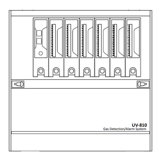
Page 7: Unit Dimensions And Components
5. Unit Dimensions and Components 5-1. Gas Alarm System Table. 1 Case type Width A (mm) 3-point 6-point 9-point (Dimensions are in mm) 12-point 15-point Figure 2. Gas Alarm System Item Component Function/Description Alarm unit Activates an alarm using lights and sounds. Indicator unit(s) Indicate gas concentration(s). -
Page 8: Indicator Unit (V3 Series)
5-2. Indicator Unit (V3 Series) Figure 3. Indicator Unit Item Component Function/Description Gas concentration bar Displays the gas concentration and alarm set values. graph display POWER light (green) Lit when the indicator unit is on. TROUBLE light (amber) Flashing when a device failure is detected in a connected gas detector or indicator unit. -
Page 9: Alarm Unit (Vas)
5-3. Alarm Unit (VAS) Exposed button type Semi-lock type Full-lock type Covered button type With front cover closed Semi-lock type Full-lock type with front cover opened with front cover opened Figure 4. Alarm Unit Item Component Function/Description Lit when the alarm unit is on. POWER light (green) Lit when a device failure in one or more indicator units, or the alarm unit TROUBLE light (amber) -
Page 10: Installation And Wiring
6. Installation and Wiring 6-1. Installation WARNING This product is not explosion-proof equipment and should not be installed in a hazardous area. CAUTION Install this product in a highly visible position in the event of an alarm, where it can be constantly monitored. - Page 11 (4) Firmly tighten all four bolts, and connect and install the removed alarm and indicator units into the case. Table 3 Length in mm Case type CAUTION 3-point Always remove connectors using plug or 6-point connector ends, and not the cable. Broken wires or poor contacts may result.
-
Page 12: Wiring
6-2. Wiring WARNING Prior to wiring, turn off the gas alarm system to prevent electric shocks. Make sure to ground the unit to prevent electric shock. 6-2-1. Wiring and Connection of Gas Detector CAUTION Ensure that the cables are correctly connected between each indicator unit/gas detector ... - Page 13 DC24V OUT DC24V OUT DC24V OUT - - - Do not ground 6芯 5-core 3芯 5芯 6-core 3-core UV-810 when the shielded cable shielded cable シールドケーブル shielded cable シールドケーブル シールドケーブル gas detector is grounded. ガス検知部 PA PB PA PB (+) (-) (+)...
- Page 14 + + + 24 VDC 24 VDC 24 VDC DC24V OUT DC24V OUT DC24V OUT - - - Do not ground UV-810 when the gas detector is grounded. Zener Barrier ツェナーバリア Class A 単独A種接地 independent grounding 2-core 5-core 5芯 2-core 2芯...
- Page 15 Dedicated terminal block Dedicated terminal block 個別接続端子台 + + 24 VDC 24 VDC DC24V OUT DC24V OUT - - Do not ground UV-810 when the 3-core 3芯 4芯 4-core gas detector is shielded cable シールドケーブル shielded cable シールドケーブル grounded. ガス検知部...
- Page 16 DC24V OUT DC24V OUT 100 VAC AC100V OUT - - Do not ground 4芯 6芯 6芯 4-core 6-core 6-core UV-810 when the shielded cable shielded cable shielded cable シールドケーブル シールドケーブル シールドケーブル gas detector is grounded. ガス検知部 A A PA PB PR PS A...
- Page 17 Each contact is electrically isolated. Alarm Reset (AR) and Alarm Silence (AS) terminals are not relay contacts. Adding a switch between N and AR/AS terminals enables alarm resetting/silencing from an external device. UV-810 UV-810 本体 総合接続端子台 Collective terminal block * When using N.C.
- Page 18 (2) Dedicated alarm contact connection To use the Dedicated alarm contacts, connect wires from external devices to the Dedicated terminal block. UV-810 本体 UV-810 Dedicated terminal block 個別接続端子台 (G) + Analog Out アナログ出力 (H) - alarm N.O. dry contact 2段目警報1a接点...
-
Page 19: Operation
7. Operation IMPORTANT Initial start-up procedure can be extremely dangerous because it uses actual gas (e.g. combustible gas, toxic gas). It is highly recommended that New Cosmos or an authorized representative should be contacted to perform the initial start-up. The accuracy of the checks and adjustments made during this start-up (e.g. -
Page 20: Maintenance
8. Maintenance Perform routine checks and annual inspection as given in the table below. Item Frequency Procedure ・ POWER lights Check that all the POWER lights are on and steady and that the system operates. ・ Bar graph displays Check that the indication/reading of the bar Daily graph displays are as expected for normal Routine check... -
Page 21: Troubleshooting
9. Troubleshooting Before making a repair request, please refer to the table below. If the gas alarm system does not return to normal operation after performing the corresponding steps in the table, or if your issue is not found in the table, consult New Cosmos or its authorized representative. -
Page 22: Specifications
10. Specifications Model UV-810 Number of Up to 15 points (Case types: 3/6/9/12/15) detection points Detection Principle As per delivery specifications Target gas As per delivery specifications Indication range As per delivery specifications Alarm set value As per delivery specifications As per gas detector specifications ・Combustible gas : ... -
Page 23: Warranty
・AC input (100-240 V), 24VDC for pump Power consumption (VA) = (V3 x number of indicator units + VAS) x 1.25 (for switching loss) Power ・DC input (24V10%), 24VDC for pump consumption Power consumption (W) = (V3 x number of indicator units + VAS) * Power consumption of gas detectors included in consumption power of V3 indicator units. -
Page 24: Glossary
13. Glossary Term Definition Indicator unit (V3) Device which receives signals from a gas detector, indicates a gas concentration, and produces a visual alarm if the target gas concentration reaches the preset alarm value, in the case of oxygen, a concentration above or below a preset limit. - Page 25 Term Definition Manual-resetting Even if a target gas concentration falls below the gas alarm set value after an alarm has been triggered, the ALARM lights and relevant gas alarm contacts will not automatically return to their normal positions. Manual-resetting is only possible when the gas concentration is below the gas alarm set value.
- Page 26 Oct 2015 Initial issue GAE-061-01 Jul 2017 Additional copies of this instruction manual may be purchased. Contact New Cosmos or its authorized representative for ordering. Authorized representative: Manufacturer: NEW COSMOS ELECTRIC CO., LTD. 2-5-4 Mitsuya-naka, Yodogawa-ku, Osaka 532-0036, Japan URL: http://www.newcosmos-global.com...
Need help?
Do you have a question about the UV-810 and is the answer not in the manual?
Questions and answers