Table of Contents
Advertisement
Quick Links
Single-Point Gas Alarm System
NV-120 series
Instruction Manual for Installation
Keep this manual for easy reference.
Prior to use, carefully read this manual as well as NV-120 series instruction manual for operation
(separate document) for correct use.
This manual describes the standard model. If your unit has end-user-specific options, this manual will be
superseded by your delivery specifications.
Instruction Manual No.
GAE-153-03
September 2022
Advertisement
Table of Contents

Subscribe to Our Youtube Channel
Related Manuals for New Cosmos Electric NV-120 Series


Summary of Contents for New Cosmos Electric NV-120 Series
- Page 1 Instruction Manual for Installation Keep this manual for easy reference. Prior to use, carefully read this manual as well as NV-120 series instruction manual for operation (separate document) for correct use. This manual describes the standard model. If your unit has end-user-specific options, this manual will be superseded by your delivery specifications.
-
Page 2: Related Manuals
The following documents have been prepared to guide your installation and use of this product. (1) NV-120 series Instruction Manual for Installation (this document), No. GAE-153-xx This document is intended for your supervisors and service personnel who are concerned with the installation of this product. -
Page 3: Introduction
(e.g., LED, beep sound, voice message), thus helping prevent incidents such as low oxygen, gas poisoning and explosion. There are various types of NV-120 series units. They are divided into four groups according to the gas detector types they are used with, and they are further divided into the following seven models according to the gas sensor types. -
Page 4: Precautions
Precautions Unauthorized copying and replication of the contents of this manual, in whole or in part, are strictly prohibited. The contents of this manual are subject to change without notice. This manual has been prepared with the utmost care. If any incorrect description comes to your notice, please contact us for correction. - Page 5 Other Signs and Symbols This manual also uses the following signs and symbols. NOTE Provides supplemental or useful information on product handling. Details the Ref. related information or procedure. Don’ts Indicates a prohibited action. Mandatory Indicates an action that must be done. Electrical hazard Warns of risk of electric shock under a certain condition.
-
Page 6: Quick Index
Quick Index This page lists parts that may be often referenced. Prior to use, please read the precautions in “1 General Precautions”. Unit Dimensions and Components Pages 8 to 13 Non-backup power type Installation Pages 16 to 21 Non-backup power type Backup power type Wiring and Connection Pages 22 to 29... -
Page 7: Table Of Contents
Table of Contents Related Manuals ............................i Introduction ............................... ii Precautions ............................iii Symbols Used in this Instruction Manual ..................iii Quick Index ............................... v General Precautions ......................... 1 1.1 Before Work ..........................1 1.2 Safety Precautions ........................1 1.3 Warning and Caution Labels Affixed to Product ............... 2 1.3.1 Warning and Caution Labels Affixed to Product ............. -
Page 8: General Precautions
1 General Precautions General Precautions 1.1 Before Work In order to ensure safe use, carefully read the precautions in this manual before turning on this product to prevent unexpected accidents. New Cosmos is not responsible for the cost incurred or any damage resulting from any usage other than that outlined in this document. -
Page 9: Warning And Caution Labels Affixed To Product
1 General Precautions Wiring and installation should only be performed by a qualified electrician with knowledge of wiring/installation procedures, in accordance with the applicable technical standards. New Cosmos is not responsible for the cost incurred or any damage resulting from controlling external equipment (e.g., interlock) by using the product’s outputs (e.g., analog output, alarm relay contact output). -
Page 10: Warning And Caution Labels Affixed To Product
1 General Precautions Warning and Caution Labels Affixed to Product 1.3.1 relocate Do not the Warning and Caution labels affixed to the product. Carefully read the contents of the labels prior to use. Item Description Power rating label Indicates the model, power source, target gas, and manufacturing date. Caution label Indicates the cautions to be adopted while handling this product. -
Page 11: Batteries
1 General Precautions 1.5 Batteries This product uses two lead storage batteries (when the unit is backup power type). The batteries need to be replaced periodically. The battery life varies depending on the frequency of use and environment conditions. Follow the precautions below for proper operation. Batteries may short-circuit resulting in electric shock or burns. -
Page 12: Battery Location
2 pcs Battery Replacement Procedure 1.5.2 Refer to “6.1.2 Battery Replacement” of the NV-120 series instruction manual for operation. Battery Life 1.5.3 If this product is to be kept unused or stored for an extended period of time, the batteries must be removed. -
Page 13: Battery Disposal
The service life of this product is 10 years. The unit can operate for up to 10 years with standard installation and operation in accordance with the NV-120 series instruction manuals for installation and operation. When the service life has expired, replacement is essential for continued reliable performance and other purposes. -
Page 14: Unit Structure
Tension screw (M6 × 40) x 2 pcs Pan-head, used for attaching bracket to panel Flat-head screwdriver Used to open/close the terminal plugs NV-120 series Instruction manual for installation (GAE-153-xx) x 1 pc instruction manual set Instruction manual for operation (GAE-154-xx) -
Page 15: Unit Dimensions And Components
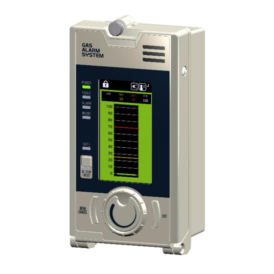
2 Unit Structure 2.2 Unit Dimensions and Components Main Unit (Exterior Appearance) 2.2.1 Non-backup power type Backup power type (mm) Item Component Description - Case - Cover Shows gas concentration on the display. Refer to “2.2.3 LCD” for details. Jog dial Turn to select item or increase/decrease the parameter value. - Page 16 Opening or audio. Gas leak or device fault alarm will be issued by beep sound and voice message. Audio opening Refer to “4.5 Audio Alarms” of NV-120 series instruction manual for operation. Battery case Comprise a backup power supply unit (backup battery x 2 pcs)
-
Page 17: Main Unit (Interior Appearance)
2 Unit Structure Main Unit (Interior Appearance) 2.2.2 Do not touch the jumper pins inside. They are for device setting. Do NOT touch these pin sockets to set the jumper pins inside Item Component Description Power switch Press to turn on/off the unit. Fuse holder Houses a 2A fuse. -
Page 18: Lcd
2 Unit Structure 2.2.3 HOME (Gas-monitoring) Target gas: Gas other than oxygen Target gas: Oxygen Item Component Description Gas concentration bar graph Displays the gas concentration and alarm set values. 1st stage gas alarm set value Displays the 1st stage gas alarm set value with orange line. 2nd stage gas alarm set value Displays the 2nd stage gas alarm set value with red line. -
Page 19: Terminal Blocks
2 Unit Structure Item Component Description ENT icon Press and hold the ENT button for confirmation. Terminal Blocks 2.2.4 Models: Models: NV-120Sx, NV-120Dx Terminal Identifier Description AC type: 100 to 240 VAC R (P) DC type: 24 VDC (+) Power AC type: 100 to 240 VAC (Input) S (N) - Page 20 2 Unit Structure *2. These common terminals are not connected (individual-common) by default, unless otherwise specified at the time of order. To connect them (to short-circuit the common lines: shared- common), refer to the attached wiring diagram (GAE-158-xx).
- Page 21 2 Unit Structure Contact Outputs Outputs to external devices (e.g., signal towers, alarm horns, etc.) are referred as “contact outputs”. NOTICE Contacts use mechanical relays, which can activate on exposure to magnet force. Install the product in a place free from a magnetic field. Do not use a magnet in the vicinity of the product.
-
Page 22: System Configuration
3 System Configuration System Configuration This NV-120 unit is paired with a gas detector (sold separately) to form a gas detection system. All the parts are connected with cables. The unit displays the gas concentration detected by the connected gas detector and produces audio-visual alarm if the concentration reaches a present limit. NV-120 Power source 100-240 VAC... -
Page 23: Preparation
4 Preparation Preparation 4.1 Tools Required The user will require the following tools for installation: ● Phillips screwdriver (#2) for M3 and M5 screws; ● Phillips screwdriver (#3) for M6 screw; ● Flat-bladed screwdriver (6mm) for knurled screw. ● Flat-bladed screwdriver (3.5mm)* used for wiring terminal blocks; *One screwdriver is provided per order, not per unit. -
Page 24: Installation
5 Installation Installation Ensure proper installation in accordance with the given specifications. Installation Flow 5.1. Installation Location 5.1.1 Installation Conditions 5.2. Product Installation 5.2.1. Wall-Mounting 5.2.2. Panel-Mounting 5.3. Wiring and Connection 5.3.1. Wiring 5.3.2. Connecting Power and Signal Lines 5.3.3. Grounding 5.3.4. -
Page 25: Installation Location
5 Installation ● Be careful not to damage the product during installation. ● Install the product in a place where it can be easily accessed for maintenance or inspection. ● Do not install the product in a place exposed to direct sunlight. Exposure to direct sunlight will cause sudden temperature change inside the product, which may impair its performance. - Page 26 5 Installation Non-backup power type Backup-power type (backup batteries included) The installation spaces can change depending on the power type, whether backup or non-backup. For the correct installation space of the gas detector, refer to its instruction manual. Installation at a raised position When installing the product at a high location, ensure that enough space is left below the product to allow for inspection or maintenance using a stepladder, among others.
-
Page 27: Product Installation
5 Installation 5.2 Product Installation There are two installation methods for the product: wall-mounting and panel-mounting. Turn off the power switch before installation. Installing the product with the power switch on may cause device failure. NOTICE The installation location changes depending on the power type, whether backup or non- backup. - Page 28 5 Installation For the backup power type, install the upper and lower mounting plates (provided) at the back of the unit using four screws. Upper mounting plate M3x6 Flat-head screw (4 places) Lower mounting plate Install wall anchors into each of the mounting holes. For the non-backup power type, turn the knurled screw counterclockwise and loosen it.
-
Page 29: Panel-Mounting
5 Installation Panel-Mounting 5.2.2 Installation procedure Remove the two grommets from the bottom of the unit. Make a square cutout in the panel as depicted below. Panel cutout size (mm) Insert the unit through the square cutout. Attach the mounting bracket S/B to the back of the unit using the two mounting screws. -
Page 30: Wiring And Connection
5 Installation cable entries on the bottom can be used. 5.3 Wiring and Connection Wiring 5.3.1 Be careful not to damage the cables during installation. Sheath all cables in a protective casing, such as a metal conduit or carbon steel pipe, as needed. Other protective structures, such as metal or concrete ducts are also acceptable. -
Page 31: Connecting Power And Signal Lines
5 Installation Connecting Power and Signal Lines 5.3.2 If needed, use a dedicated breaker for the power line going towards the product. Ensure that the power voltage supplied to the product is within the specifications. Ensure that the load resistance of the signal line, including the resistance of the wire, is 300 ohm or less. - Page 32 5 Installation Fully insert the tip of each wire into the round slot. While holding the wire, remove the screwdriver from the square slot. This will securely connect the wire to the terminal. Slightly pull the wire to ensure that it is secure in the terminal. To remove the wire from the terminal Insert the screwdriver into the square slot to open its corresponding round slot.
-
Page 33: Grounding
5 Installation Grounding 5.3.3 ● Wiring and installation must be only performed by a qualified electrician with knowledge of wiring/installation procedures in accordance with the applicable technical standards. ● For wiring of the gas detector, refer to its instruction manual. (... -
Page 34: Connecting To Gas Detector
5 Installation Connecting to Gas Detector 5.3.4 The wiring configuration changes depending on the given specifications. Check the group/model variation of your unit (page ii) prior to wiring. ● Connect the wires to their corresponding terminals by referring to the identifiers marked on both the product and the gas detector. - Page 35 5 Installation Typical configuration for Group 3 (NV-120Mx) 3-core 3/4-core 2-core shielded cable shielded cable shielded cable Diffusion type gas detector Extractive-type gas detector Diffusion/extractive-type gas detector (Pump power: 24 VDC) (Power: 100 VAC) Typical configuration for Group 4 (NV-120Ci / NV-120Hi) 4-core cable 6-core cable Diffusion type gas detector...
-
Page 36: Connecting To External Devices
5 Installation Connecting to External Devices 5.3.5 ( 1 ) Connecting to an external controller or annunciator Normally open or closed dry contacts are turned on/off for activating/deactivating a 1st stage gas alarm, 2nd stage gas alarm, and fault alarm. New Cosmos is not responsible for the costs incurred or any damage resulting from controlling external equipment (e.g. - Page 37 5 Installation ( 3 ) Connection to external switch terminals There are two external switch terminals: “AR” and “AS”. To use the unit as semi-lock type, connect the panel’s alarm reset button to the “AS” terminal. This enables to reset an alarm from both the external device and the unit. To use the unit as full-lock type, connect the audio alarm mute button to the “AS’...
-
Page 38: Operation Check
Measure the input voltage to check that the value is within the specification. Set the power switch to the on position. Check the unit turns on normally. Power switch Refer to “4. Operation” of the NV-120 series instruction manual for operation (separate Ref. document) for more information. -
Page 39: Glossary
6 Glossary Glossary Term Definition Alarm unit Device that indicates the gas concentration and activates an alarm according to the signals received from a connected gas detector. Backup power supply Battery unit that provides emergency power to the product when the input unit power source or main power fails. - Page 40 6 Glossary Clean air or normal air Standard atmosphere which contains 20.9 to 21.0% oxygen in dry condition or atmosphere without target gas or interference gases. Term Definition Auto-resetting After an alarm has been triggered, and a target gas concentration falls below the gas alarm set value minus 2% of the full-scale value, the ALARM lights and relevant gas alarm contacts will automatically return to their normal positions.
- Page 42 GAE-153-01 GAE-153-02 December 2020 GAE-153-03 September 2022 Additional copies of this instruction manual may be purchased. Contact New Cosmos or its authorized representative for ordering. Authorized representative: Manufacturer: NEW COSMOS ELECTRIC CO., LTD. 2-5-4 Mitsuya-naka, Yodogawa-ku, Osaka 532-0036, Japan http://www.new-cosmos.co.jp...
Need help?
Do you have a question about the NV-120 Series and is the answer not in the manual?
Questions and answers