Advertisement
Quick Links
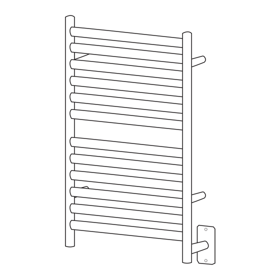
Cape Heated Towel Rack Installation Guide
•
•
The unit requires a 120 volt, 60Hz power source and should be installed on a GFCI protected circuit.
•
Follow installation instructions to ensure unit is securely fixed to wall.
•
Unit is designed for hanging, drying and warming towels or other articles of clothing. Under no circumstances should
anybody climb on or hang on unit.
•
Unit is intended for indoor use.
•
Surface temperature can increase depending on the ambient temperature in the room and the number of towels applied to
the unit.
•
The fasteners provided with the installation kit are for convenience only and are not suitable for all installations.
•
To ensure the Heated Towel Rail is mounted securely, fasteners should be secured in studs or structural members placed
behind the rails.
•
It is the ultimate responsibility of the installer to ensure proper mounting hardware is employed in attaching the unit to the
wall.
•
After installation, connect the electric power.
•
•
This rack is designed and safe to run continuously with a simple on/off switch for control. However, it can also be wired to
a timer for scheduled control.
•
Towels which contain soap or detergent residue may appear to have scorch marks; this is simply discoloration of the
residue. These discoloration marks will disappear after a couple of wash cycles.
•
The unit is constructed from extremely durable 304 stainless steel. To maintain a good appearance, follow these simple
instructions:
1.
For routine cleaning, simply switch off the unit, allow to cool to room temperature, wipe with a damp cloth and buff
with a soft, dry cloth.
2.
Under no circumstances should abrasive cleaners be used to clean the unit.
Included Components
A
B
x4
SLOTTED
LEG EXTEN
BOLT
SION
F
G
x4
TAPERED
WIRE
BUSHING
CONNECTOR
Mounting Leg Assembly
Loosen the set screw D to release tapered
bushing F from Leg Extension B
F
A
Step 1
Fasten the bolt into the threaded nut welded onto the back of the unit, using a flat head screw driver, as shown in
where to install unit and the location of the single gang junction box. This can be done by either placing the
assembled rack against the wall or taking approximate dimensions from the drawing supplied.
C
D
x4
x1
COVER
SET
PLATE
SCREW
H
I
x6
x1
MARKING
ALAN
DISK
KEY
D
B
E
x4
x4
WOOD
SCREW
J
x2
x2
COVER PLATE
SCREW
B
A
FIG 1
Tools Required
B
D
A
FIG 2
2023.6
FIG 3
1
Advertisement

Subscribe to Our Youtube Channel
Related Manuals for Amba Cape 2332.1


Summary of Contents for Amba Cape 2332.1
- Page 1 2023.6 Cape Heated Towel Rack Installation Guide • • The unit requires a 120 volt, 60Hz power source and should be installed on a GFCI protected circuit. • Follow installation instructions to ensure unit is securely fixed to wall. • Unit is designed for hanging, drying and warming towels or other articles of clothing.
- Page 2 Step 2 Loosen the set screw at the bottom of the short feeder pipe where the electrical cord exits the unit. Position the slotted pipe on the electrical cord over the feeder pipe with the cut-away section facing downwards. Position the rubber grommet into the slot to protect the electrical cord.
Need help?
Do you have a question about the Cape 2332.1 and is the answer not in the manual?
Questions and answers