Table of Contents
Advertisement
Quick Links
INSTRUCTION MANUAL
10 INCH PORTABLE TABLE SAW
MANUAL DE INSTRUCCIONES
SIERRA DE MESA PORTÁTIL DE
10 PULGADAS CON BASE
Español (28)
www.ShopMasterMachinery.com
Instruction Manual
Manual de instrucciones
To reduce the risk of serious injury, thoroughly read and comply with all warnings and instructions in this
manual and on product KEEP THIS MANUAL NEAR YOUR PRODUCT FOR EASY REFERENCE AND TO
INSTRUCT OTHERS
S36-295 T3
Advertisement
Table of Contents

Related Manuals for ShopMaster DELTA S36-295 T3


Summary of Contents for ShopMaster DELTA S36-295 T3
- Page 1 INSTRUCTION MANUAL 10 INCH PORTABLE TABLE SAW MANUAL DE INSTRUCCIONES SIERRA DE MESA PORTÁTIL DE 10 PULGADAS CON BASE Español (28) S36-295 T3 www.ShopMasterMachinery.com Instruction Manual Manual de instrucciones To reduce the risk of serious injury, thoroughly read and comply with all warnings and instructions in this manual and on product KEEP THIS MANUAL NEAR YOUR PRODUCT FOR EASY REFERENCE AND TO INSTRUCT OTHERS...
-
Page 2: Table Of Contents
Heeling (Paralleling) Blade to Miter Gauge Groove ..20 FUNCTIONAL DESCRIPTION Specifications The SHOPMASTER S36-295 T3 10-inch Portable Table Saw is designed to help you achieve your home improvement and home shop needs. This saw can tackle nearly any DIY project MAX DEPTH OF CUT AT 90°:... -
Page 3: Important Safety Instructions
IMPORTANT SAFETY INSTRUCTIONS CAREFULLY READ AND FOLLOW ALL WARNINGS AND INSTRUCTIONS ON YOUR PRODUCT AND IN THIS MANUAL. SAVE THIS MANUAL. MAKE SURE ALL USERS ARE FAMILIAR WITH ITS WARNINGS AND INSTRUCTIONS WHEN USING THE TOOL. Improper operation, maintenance or modification of tools or equipment could result in serious injury and/or property damage. SAFETY SYMBOLS-DEFINITIONS This manual contains information that is important for you to know and understand. -
Page 4: General Power Tool Safety Warnings
GENERAL POWER TOOL SAFETY WARNINGS Read all safety warnings, instructions, illustrations and specifications provided with this power tool. Failure to follow all instructions listed below may result in electric shock, fire and/or serious injury. Save all warnings and instructions for future reference. The term “power tool”... -
Page 5: Terminology
TABLE SAW SAFETY RULES TERMINOLOGY THE FOLLOWING TERMS WILL BE USED THROUGHOUT THE MANUAL AND YOU SHOULD BECOME FAMILIAR WITH THEM. THROUGH-CUT - any cut that completely cuts through the FREEHAND - cutting without the use of a miter gauge or rip fence workpiece. -
Page 6: Making A Push Stick
TABLE SAW SAFETY RULES Feed workpiece at an even pace. Do not bend or twist the workpiece. If jamming occurs, turn the tool off immediately, unplug the tool then clear the jam. Jamming the saw blade by the workpiece can cause kickback or stall the motor. Do not remove pieces of cut-off material while the saw is running. -
Page 7: Proposition 65 Warning
PROPOSITION 65 WARNING: Some dust created by power sanding, sawing, grinding, drilling, and other construction activities contains chemicals known to the state of California to cause cancer, birth defects or other reproductive harm. Some examples of these chemicals are: • Lead from lead-based paints •... -
Page 8: Double Insulation
POWER CONNECTIONS DOUBLE INSULATION This machine is double insulated. Double insulation is a concept in safety in electric power tools, which eliminates the need for the usual three-wire grounded power cord. All exposed metal parts are isolated from the internal metal motor components with protecting insulation. -
Page 9: Hardware Bag Contents
UNPACKING HARDWARE BAG CONTENTS Description (QTY) a. M5 x 25mm Hex Socket Cap Screw (6) e. Hand Wheel Shoulder Screw (1) b. M5 Flat Washer (1) f. Handle Wheel Knob (1) g. 4mm Hex/Phillips Wrench (1) c. M5 Kep Nut (2) d. -
Page 10: General Parts Knowledge
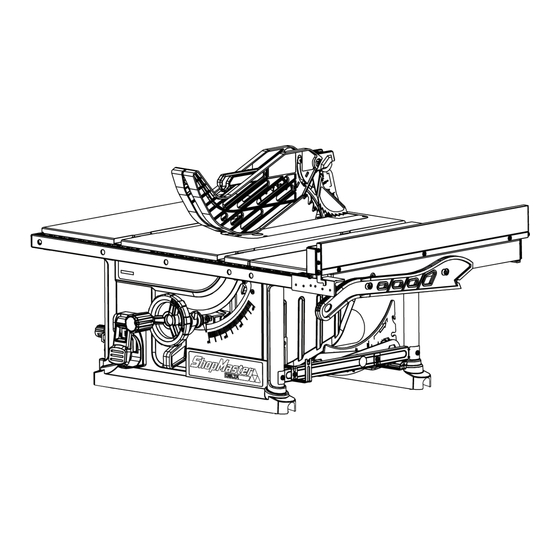
GENERAL PARTS KNOWLEDGE ANTI-KICKBACK PAWLS BLADE GUARD RIVING KNIFE TABLE THROAT PLATE SCALE RIP FENCE FENCE RAIL HEIGHT PUSH STICK ADJUSTMENT WHEEL MITER GAUGE BEVEL SCALE ON/OFF SWITCH BEVEL LOCK ASSEMBLY The part and hardware names and letters correspond to those shown in General Parts Knowledge, Shipping Contents, and the Hardware Contents. -
Page 11: Fence Rail And Extension Wing Assembly
ASSEMBLY FENCE RAIL AND EXTENSION WING ASSEMBLY Attach fence rail (K), scale side up (16 in. side of scale to the right), to the front of the saw using (4) M5 x 25mm hex socket cap screws (a) as shown in Fig. 2, making sure rail is properly RAIL SUPPORT seated on each rail support on the front of the table. -
Page 12: Installing/Changing Blade
Place blade on the arbor shaft with the teeth on the blade WASHER pointing toward the front of the saw. SHOPMASTER logo on the blade will be facing toward the left side of the saw. Place flanged washer on the shaft with the large side of the washer towards the blade, then secure blade assembly with nut. -
Page 13: Insert And Level Throat Plate
ASSEMBLY Refer to Fig. 8 & 9. This saw is shipped with its riving knife installed in the lowered or “non-thru cut” position. This riving knife matches the thickness of the blade that is shipped with your saw. To install the anti-kickback pawls and the blade guard assembly, first raise the riving knife from the lowered or “non-thru cut”... -
Page 14: Anti-Kickback Pawls And Blade Guard
ASSEMBLY ANTI-KICKBACK PAWLS AND BLADE GUARD Riving knife (E) must be in the Through Cut position prior to installation of the anti-kickback pawls (D) and blade guard (F) (Fig. 12 and 13). Insert the pawl assembly (D) into the middle slot on the riving knife (E) as shown in (Fig. -
Page 15: Operation
OPERATION ailure to comply with the following warnings may result in serious personal injury. READ ENTIRE MANUAL. In addition to reading these operating instructions, it is important to read and understand the entire manual before operating this saw. Follow all applicable instructions regarding assembly, preparation, and adjustment prior to making any cuts and comply with all safety rules and warnings in this section and elsewhere throughout this manual. -
Page 16: Storage
STORAGE On-Board Storage C. Push Stick F. Blade Guard B. Rip Fence Storage is located on the right panel as shown in E. Riving Knife (Behind D. Anti-Kickback Pawls H. Miter Gauge (Fig. 19 & 20). Blade Guard) Figure 19 Figure 20 MAKING CUTS Failure to comply with the following warnings may result in serious personal injury. -
Page 17: Rip Cuts
MAKING CUTS RIP CUTS • Rip cutting: Rip cutting is performed predominantly in a parallel direction with the grain of the wood. • Make sure blade is parallel to miter gauge slot prior to cutting. Instructions for adjustment on page 19. Remove miter gauge. -
Page 18: Crosscutting
MAKING CUTS CROSSCUTTING • Cross cutting: Cross cutting is performed predominantly in Make sure the workpiece is clear of the blade - at least a perpendicular direction with the grain of the wood. 1 inch or 25mm away - before starting the saw. •... -
Page 19: Compound Miter Cuts
MAKING CUTS COMPOUND MITER CUTS This is a combination of bevel crosscutting and mitering. Refer to (Fig. 25) and follow the instructions for both bevel crosscutting and mitering. Remember to use the right miter slot on the right side of the blade for all bevel cuts. LARGE PANEL CUTS Place workpiece supports at the same height as the saw table behind saw to support the cut workpiece, and alongside (s) of... -
Page 20: Heeling (Paralleling) Blade To Miter Gauge Groove
MAKING CUTS CHECKING BLADE PARALLELISM TO MITER GAUGE GROOVE (HEEL) See Figures 26 & 27. • Blade (A) MUST be parallel to miter gauge groove so that wood does not bind, resulting in kickback. Failure to do so could result in serious personal injury. -
Page 21: Cutting Aids And Accessories
CUTTING AIDS AND ACCESSORIES PUSH STICK In order to operate your table saw safely, you must use a push stick whenever the size or shape of the workpiece would otherwise cause your hands to be within 6-inches (152mm) of the saw blade or other cutter. A push stick is included with this saw. No special wood is needed to make additional pushsticks as long as it is sturdy and long enough with no knots, checks or cracks. -
Page 22: Push Block
CUTTING AIDS AND ACCESSORIES PUSH BLOCK Push blocks are blocks used to securely hold down the workpiece against the table. They include some gripping surface or handle to hold the block. Any screws running through the underside of the block to fasten the handle should be recessed in order to avoid contact with the workpiece. -
Page 23: Cut Off Gauge
CUTTING AIDS AND ACCESSORIES CUT OFF GAUGE When crosscutting a number of pieces to the same length, you can clamp a block of wood (A) (Fig. 33) to the fence and use it as a cut-off gauge. The block (A) must be at least inch 4"... -
Page 24: Adjusting The Bevel Stops
CUTTING AIDS AND ACCESSORIES ADJUSTING THE BEVEL STOPS cam screw Adjustment to the bevel stops may be required if the blade is not vertically square to the table when bevel adjustment is set at 0˚ or does not go to 45˚... -
Page 25: Riving Knife Adjustment
RIVING KNIFE ADJUSTMENT RIVING KNIFE HEIGHT ADJUSTMENT AND ALIGNMENT To change the position of the riving knife, remove the throat plate then raise the blade assembly to the highest position by turning the height adjustment wheel clockwise on the front of the saw. -
Page 26: Riving Knife Alignment
RIVING KNIFE ALIGNMENT If the riving knife has vertical misalignment, adjust as follows using Fig. 40 and Fig. 42: Loosen the 2 hex socket head screws (AA). Make adjustments to (BB2) and (BB3), to align riving knife to the blade. No adjustment is needed for (BB1). Tighten screws (AA). -
Page 27: Accessories
PARTS, SERVICE OR WARRANTY ASSISTANCE All SHOPMASTER Machines and accessories are manufactured to high quality standards and are serviced by a network of DELTA ® Authorized Service Centers. To obtain additional information regarding your product or to obtain parts, service, warranty assistance, or the location of the nearest service center, please call 1-800-223-7278. -
Page 28: Spanish
2651 New Cut Road Spartanburg, SC 29303 (800) 223-7278 www.ShopMasterMachinery.com © 2024 Delta Power Equipment Corporation DPEC007872 Revision Date: 07/30/2024 REV2...
Need help?
Do you have a question about the DELTA S36-295 T3 and is the answer not in the manual?
Questions and answers