Table of Contents
Advertisement
Available languages
Available languages
10-INCH SLIDING COMPOUND MITER SAW
SCIE À ONGLET COMBINE
254 MM
SIERRA INGLETADORA
COMPUESTA DE 10
PULGADAS
Français (22)
Español (44)
www.DeltaMachinery.com
Instruction Manual
Manual d'utilisation
Manual de instrucciones
To reduce the risk of serious injury, thoroughly read and comply with all warnings and instructions in this manual and on product.
KEEP THIS MANUAL NEAR YOUR PRODUCT FOR EASY REFERENCE AND TO INSTRUCT OTHERS
S26-261L
Advertisement
Chapters
Table of Contents

Related Manuals for ShopMaster S26-261L


Summary of Contents for ShopMaster S26-261L
- Page 1 Français (22) Español (44) www.DeltaMachinery.com Instruction Manual S26-261L Manual d’utilisation Manual de instrucciones To reduce the risk of serious injury, thoroughly read and comply with all warnings and instructions in this manual and on product. KEEP THIS MANUAL NEAR YOUR PRODUCT FOR EASY REFERENCE AND TO INSTRUCT OTHERS...
-
Page 2: Table Of Contents
TABLE OF CONTENTS IMPORTANT SAFETY INSTRUCTIONS ........2 POWER SWITCH LOCK.............14 GENERAL POWER TOOL SAFETY RULES ......3 TO SLIDE CUT ..............15 PROPOSITION 65 WARNING ........... 4 TIPS FOR CUTTING AND SUPPORTING WORKPIECE .. 16 MITER SAW SAFETY RULES ........... 4 CUTTING WARPED MATERIAL ........ -
Page 3: General Power Tool Safety Rules
GENERAL POWER TOOL SAFETY RULES FAILURE TO FOLLOW THESE RULES MAY RESULT IN SERIOUS PERSONAL INJURY. • READ INSTRUCTION MANUAL AND KNOW YOUR or plugging in the cord. TOOL. Read and familiarize yourself with entire instruction • USE RECOMMENDED ACCESSORIES. Consult manual manual. -
Page 4: Proposition 65 Warning
GENERAL POWER TOOL SAFETY RULES • This machine is designed and intended for use by properly or other injury. Always use NIOSH/OSHA approved trained and experienced personal only. If you are not respiratory protection appropriate for the dust exposure. familiar with the proper and safe operation of this product, Direct particles away from face and body. -
Page 5: Power Connections
MITER SAW SAFETY RULES scrap, or anything else that is in or near the cutting off the power switch, remove the miter saw plug from path of the blade. the power source and have damaged, missing, or failed parts replaced before resuming operation. •... -
Page 6: Features
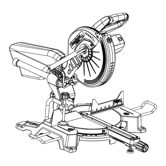
POWER CONNECTIONS ELECTRICAL CONNECTION This tool has a precision-built electric motor. It should be connected to a POWER SUPPLY THAT IS 120 VOLTS, 60 HZ, AC ONLY (NORMAL HOUSEHOLD CURRENT). Do not operate this tool on direct current (DC). A substantial voltage drop will cause a loss of power and the motor will overheat. - Page 7 FEATURES A. Motor B. Fence C. Throat Plate D. Miter Lock Knob E. Support Extensions Miter Scale with Positive Stops G. Horizontal Work Clamp H. Base Mounting Holes J. On-Board Wrench K. Work Table L. Bevel Lock Knob M. Dust Bag N.
-
Page 8: Unpacking And Assembly
If any parts are missing, do not attempt to plug in the power cord and turn the power on. The saw should only be energized after all parts have been located and correctly assembled. FIGURE 2 CONTENT DESCRIPTION (QTY) A. SHOPMASTER #S26-261L 10-inch Sliding D. Blade Wrench (1) Compound Miter Saw E. AAA Batteries (2) B. -
Page 9: Assembly
ASSEMBLY • Do not attempt to modify this tool or create accessories not recommended for use with this tool. Any such alteration or modification is misuse and could result in a hazardous condition. • Do not connect to power supply until assembly is complete. Failure to comply could result in accidental starting. •... -
Page 10: Attaching Work Clamp
ASSEMBLY ATTACHING WORK CLAMP The horizontal work clamp secures the workpiece to the fence to provide more stability and keeps the workpiece from creeping toward the saw blade. Depending on the cutting operation and the size of the workpiece, it may be preferable to use a C-clamp instead of the work clamp to secure the workpiece to the miter table prior to making the cut. -
Page 11: Preparing Your Saw For Use
PREPARING YOUR SAW FOR USE INSTALL/REPLACE THE BLADE A 10-inch blade is the maximum blade capacity of the saw. Larger blades will come in contact with the blade guards. Refer to Figure 9. 1. Make sure the saw is unplugged. 2. -
Page 12: Align The Blade To The Table
PREPARING YOUR SAW FOR USE ALIGN THE BLADE TO THE TABLE Refer to Figure 11. 1. Unplug the saw 2. Lower the saw arm all the way down to the transport position and engage the lock pin to hold it in place. 3. -
Page 13: Using The Laser Guide
PREPARING YOUR SAW FOR USE USING THE LASER GUIDE When the laser guide switch is turned on it projects a red line onto the work surface enabling you to see your cut before you make it. To ensure a true and straight cut: 1. -
Page 14: Operation
OPERATION • Do not allow familiarity with tools to make you careless. Remember that a careless fraction of a second is sufficient enough to inflict serious personal injury. • Always wear eye protection with side shields and marked to comply with ANSI Z87.1 Failure to do so could result in objects being thrown into your eyes, resulting in possible serious personal injury. -
Page 15: To Slide Cut
OPERATION TO SLIDE CUT Never make a cut by pulling the saw toward you. The blade can “climb” on top of the workpiece and come toward you at an accelerated speed. Failure to heed this warning could result in serious personal injury. See Figure 16 With the saw off, pull the saw arm forward. -
Page 16: Tips For Cutting And Supporting Workpiece
OPERATION TIPS FOR CUTTING AND SUPPORTING WORKPIECES TIPS FOR CUTTING CROWN MOLDING • The two edges of the molding that contact the ceiling and the wall are at angles that, when added together, equal exactly 90°. Most crown molding has a top rear angle (the section that fits flat against the ceiling) of 52° and a bottom rear angle (the section that fits flat against the wall) of 38°. -
Page 17: Cutting Warped Material
OPERATION CUTTING WARPED MATERIAL When attempting to cut warped material, the CONVEX face should be against the fence as shown in Figure 17. Never position a piece of warped material with the CONCAVE face or edge against the fence, as shown in Figure 18. -
Page 18: Supporting Long Workpieces
If the saw arm does not raise by itself or if there is play in FIGURE 21 the pivot joints, it will need to be professionally repaired at an AUTHORIZED SHOPMASTER® SERVICE CENTER. Please call Company’s Customer Care Center at 800-223- 7278. -
Page 19: Bevel Pivot
0° and 45°. If it does not or if there is play in the pivot, the saw must be repaired by an AUTHORIZED SHOPMASTER SERVICE CENTER. LASER ADJUSTMENTS This saw is equipped with an adjustable laser which projects a red line onto the work piece surface, see Figure 22. -
Page 20: Depth Stop Adjustment
ADJUSTMENTS LASER VERTICAL ANGLE ADJUSTMENT If you notice the laser line does not remain parallel to the blade as the saw head is lowered to make a cut refer to Figure 24 and follow these instructions: using a Phillips head screwdriver turn the screw (B) to adjust the vertical angle of the laser. -
Page 21: Maintenance
MAINTENANCE To reduce the risk of injury, turn unit off Use clean cloths to remove dirt, dust, oil, grease, etc. and disconnect it from power source Do not at any time let brake fluids, before cleaning or servicing, before installing and gasoline, petroleum-based products, removing accessories, before adjusting when making penetrating oils, etc., come in contact with plastic parts. -
Page 22: Accessories
Three Year Limited Warranty WHAT IS COVERED. Delta Power Equipment Corporation (“Company”) will, at its option, repair or replace this SHOPMASTER product, if purchased at retail in the United States or Canada and the product, with normal use, has proven to be defective in workmanship or material, subject to the conditions stated in this Limited Warranty. - Page 23 Français (22) Español (44) www.DeltaMachinery.com Instruction Manual Instruction Manual S26-261L Manual d’utilisation Manual de instrucciones Pour réduire les risques de blessure grave, veuillez lire attentivement et respecter AVERTISSEMENT : toutes les mises en garde et directives dans ce guide et sur le produit.
- Page 24 TABLE DES MATIÈRES VERROUILLAGE DU COMMUTATEUR ......35 CONSIGNES IMPORTANTES DE SÉCURITÉ ....... 23 FAIRE UNE COUPE EN GLISSIÈRE ......... 36 RÈGLES DE SÉCURITÉ GÉNÉRALES POUR LES OUTILS ÉLECTRIQUES ............24 CONSEILS POUR LA DÉCOUPE ET LE SOUTIEN DE PIÈCE ................37 AVERTISSEMENT DE LA PROPOSITION 65 .......
-
Page 25: Règles De Sécurité Générales Pour Les Outils Électriques
RÈGLES DE SÉCURITÉ GÉNÉRALES POUR LES OUTILS ÉLECTRIQUES AVERTISSEMENT : LE NON-RESPECT DES CONSIGNES SUIVANTES PEUT ENTRAÎNER DES BLESSURES GRAVES. • LIRE ET GUIDE ET CONNAÎTRE VOTRE OUTIL. Lisez le INTEMPESTIVE, assurez-vous que les interrupteurs sont guide d’utilisation en entier pour vous familiariser avec son en position «... -
Page 26: Avertissement De La Proposition 65
RÈGLES DE SÉCURITÉ GÉNÉRALES POUR LES OUTILS ÉLECTRIQUES • la poussière, lorsque possible. Éviter de respirer les de sciage, de meulage, de perçage et autres activités poussières et éviter le contact prolongé avec la poussière. de construction. Portez des vêtements de protection et Laisser la poussière pénétrer dans la bouche, les yeux nettoyez les parties exposées avec de l'eau et du savon. -
Page 27: Branchements D'alimentation
RÈGLES DE SÉCURITÉ DE LA SCIE À ONGLETS • Ne déplacez JAMAIS la pièce ou ne faites aucun pièces endommagées, manquantes ou défectueuses réglage de l'angle de coupe pendant que la scie est avant de reprendre l'opération. en marche ou que la lame tourne. Tout glissement •... -
Page 28: Fonctions
BRANCHEMENTS D’ALIMENTATION BRANCHEMENT ÉLECTRIQUE Cet outil dispose d’un moteur électrique de précision. Il doit être branché à une ALIMENTATION DE 120 VOLTS, 60 HZ, CA SEULEMENT (COURANT RÉSIDENTIEL NORMAL). Ne faites pas fonctionner cet outil sur courant continu (CC). Une chute de tension importante causerait une perte de puissance et le moteur surchaufferait. - Page 29 FONCTIONS A. Moteur B. Guide C. Plaque à gorge D. Manette de blocage de l’onglet E. Rallonges de support Jauge à onglets avec butées fixes G. Étau horizontal H. Base Trous de montage J. Clé embarquée K. Table de travail L.
-
Page 30: Déballage Et Montage
La scie ne doit être mise sous tension que si toutes les pièces ont été trouvées et correctement assemblées. FIGURE 2 DESCRIPTION DU CONTENU (QTÉ) A. Scie à onglets combinée coulissante de 10 po, D. Clé pour lame (1) SHOPMASTER N S26-261L E. Piles AAA (2) B. Sac à poussières (1) Rallonges de support (2) -
Page 31: Montage
MONTAGE AVERTISSEMENT : • N'essayez pas de modifier cet outil ou de créer des accessoires non recommandés pour cet outil. Toute modification de ce genre constitue une mauvaise utilisation et peut entraîner une situation dangereuse. • Ne pas brancher sur l’alimentation avant que le montage ne soit terminé. Le non-respect de cette consigne peut entraîner un démarrage accidentel. -
Page 32: Fixer L'étau
MONTAGE FIXER L'ÉTAU L'étau horizontal maintient la pièce contre le guide pour assurer une plus grande stabilité et il empêche la pièce de se déplacer vers la lame de scie. Selon l’opération de coupe et la taille de la pièce, il peut être préférable d’utiliser une presse en C au lieu de l'étau pour immobiliser la pièce à... -
Page 33: Préparer Votre Scie Pour L'utilisation
PRÉPARER VOTRE SCIE POUR L’UTILISATION INSTALLER/REMPLACER LA LAME AVERTISSEMENT : Une lame de 10 pouces est la capacité maximale de lame de la scie. Des lames plus grandes entreront en contact avec les protège-lames. Reportez-vous à la figure 9. 1. Assurez-vous que la scie est débranchée. 2. -
Page 34: Aligner La Lame À La Table
PRÉPARER VOTRE SCIE POUR L’UTILISATION ALIGNER LA LAME À LA TABLE Reportez-vous à la figure 11. 1. Débranchez la scie. 2. Abaissez le bras de la scie jusqu'à la position de transport et engagez la goupille de verrouillage pour le maintenir en place. 3. -
Page 35: Utilisation Du Guide Laser
PRÉPARER VOTRE SCIE POUR L’UTILISATION UTILISATION DU GUIDE LASER Lorsque le guide laser est allumé (avec le commutateur), il projette une ligne rouge sur la surface de travail, vous permettant de voir votre coupe avant de la réaliser. Pour assurer une coupe exacte et droite : 1. -
Page 36: Utilisation
UTILISATION AVERTISSEMENT : • Ne laissez pas la familiarité avec l'outil vous faire oublier la prudence. Rappelez-vous qu'une fraction de seconde d'imprudence est bien suffisante pour infliger une blessure personnelle grave. • Portez toujours des lunettes de protection avec écrans latéraux et marqués pour se conformer à la norme ANSI Z87.1. -
Page 37: Faire Une Coupe En Glissière
UTILISATION FAIRE UNE COUPE EN GLISSIÈRE AVERTISSEMENT : Ne faites jamais une coupe en tirant la scie vers vous. La lame peut « grimper » sur le dessus de la pièce et venir vers vous à une vitesse accélérée. Le non-respect de cet avertissement pourrait entraîner des blessures. -
Page 38: Conseils Pour La Découpe Et Le Soutien De Pièce
UTILISATION CONSEILS POUR LA DÉCOUPE ET LE SOUTIEN DES PIÈCES CONSEILS POUR COUPE DE MOULURE COURONNÉE • Les deux bords du moulage qui entrent en contact avec le plafond et le mur sont à des angles qui, lorsqu'ils sont ajoutés, font exactement 90°. La plupart des moulures couronnées ont un angle arrière supérieur (la section qui se place à... -
Page 39: Coupe De Matériau Déformé
UTILISATION COUPE DE MATÉRIAU DÉFORMÉ Lorsque vous essayez de couper un matériau déformé, la face CONVEXE doit être contre le guide comme illustré sur la figure 17. Ne placez jamais un morceau de matériau déformé avec la face ou le bord CONCAVE contre le guide, comme illustré... -
Page 40: Soutien Des Longues Pièces
être réparé par un professionnel à un CENTRE DE SERVICE SHOPMASTER® AUTORISÉ. Veuillez appeler le service à la clientèle de la société au 1-800-223-7278. VIS DE BUTÉE FIXE La position de la vis de réglage de butée fixe a été... -
Page 41: Pivot Pour Coupe Biseautée
0° et 45°. Si ce n'est pas le cas ou s'il y a du jeu dans l’articulation du pivot, la scie devra être réparée à un CENTRE DE SERVICE SHOPMASTER AUTORISÉ. RÉGLAGE DU LASER Cette scie est munie d’un laser ajustable qui projette... -
Page 42: Ajustement De La Profondeur
RÉGLAGES RÉGLAGE DE L’ANGLE VERTICAL DU LASER Consultez la figure 24 et suivez les instructions suivantes si vous remarquez que la ligne du laser ne demeure pas parallèle avec la lame lorsque la tête de la scie est baissée pour effectuer une coupe : tournez la vis (B) avec un tournevis à... -
Page 43: Entretien
ENTRETIEN etc. AVERTISSEMENT : Pour réduire les risques de blessures, éteignez l'appareil et débranchez-le de la AVERTISSEMENT : Ne jamais laisser les liquides de source d'alimentation avant le nettoyage ou l'entretien, freins, l'essence, les produits à base de pétrole, les huiles avant d'installer et de retirer tout accessoire et avant de pénétrantes, etc., entrer en contact avec les pièces en faire des réglages lors de réparations. -
Page 44: Dépannage
Puisque les accessoires autres que ceux offerts par DELTA n’ont pas été testés avec ce produit, ® l'utilisation de ces accessoires peut être dangereuse. Pour une utilisation sécuritaire, seuls les accessoires DELTA ® SHOPMASTER recommandés doivent être utilisés avec ce produit. -
Page 45: Assistance Pour Pièces, Services Ou Garantie
PÉRIODE DE GARANTIE Toutes les réclamations de garantie doivent être soumises dans les trois ans suivant la date d’achat au détail. Pour toutes les pièces d'entretien et les produits SHOPMASTER remis à neuf en usine, la période de garantie est de 180 jours. -
Page 46: Français
Español (44) www.DeltaMachinery.com Instruction Manual Instruction Manual Manual d’utilisation S26-261L Manual de instrucciones Para reducir el riesgo de lesiones graves, lea detenidamente y cumpla con todas ADVERTENCIA: las advertencias e instrucciones en este manual y en el producto. MANTENGA ESTE MANUAL CERCA DE SU PRODUCTO PARA UNA REFERENCIA FÁCIL Y PARA BRINDAR... -
Page 47: Instrucciones De Seguridad Importantes
ÍNDICE INSTRUCCIONES DE SEGURIDAD IMPORTANTES ... 44 FUNCIONAMIENTO ..............56 REGLAS DE SEGURIDAD GENERALES PARA LAS BLOQUEO DEL INTERRUPTOR DE ENCENDIDO ... 56 HERRAMIENTAS MOTORIZADAS ......... 45 CORTE DESLIZANTE ............57 ADVERTENCIA DE LA PROPUESTA 65 ........ 46 RECOMENDACIONES PARA CORTAR Y APOYAR REGLAS DE SEGURIDAD DE LA SIERRA LA PIEZA DE TRABAJO ............ -
Page 48: Reglas De Seguridad Generales Para Las Herramientas Motorizadas
REGLAS DE SEGURIDAD GENERALES PARA LAS HERRAMIENTAS MOTORIZADAS ADVERTENCIA: NO SEGUIR ESTAS REGLAS PODRÍA PROVOCAR LESIONES PERSONALES GRAVES. • LEA EL MANUAL DE INSTRUCCIONES Y FAMILIARÍCESE de encendido. CON LA HERRAMIENTA. Lea y familiarícese con todo • PARA REDUCIR EL RIESGO DE UN ARRANQUE el manual de instrucciones. -
Page 49: Advertencia De La Propuesta 65
REGLAS DE SEGURIDAD GENERALES PARA LAS HERRAMIENTAS MOTORIZADAS • irreversibles u otras lesiones, incluida la silicosis (una • Evite el contacto prolongado con el polvo proveniente del enfermedad pulmonar grave), cáncer o muertes. No lijado, corte, esmerilado, perforación y de otras actividades permita que las partículas entren en contacto con el de construcción. -
Page 50: Conexiones De Alimentación
REGLAS DE SEGURIDAD DE LA SIERRA INGLETADORA • NUNCA coloque, bajo ninguna circunstancia, las algún componente eléctrico no funcione de forma manos o dedos detrás, debajo o a una distancia de 7 correcta, apague el interruptor de encendido, centímetros (3 pulgadas) de la hoja en movimiento y extraiga el enchufe de la sierra ingletadora de la su trayectoria de corte. -
Page 51: Características
CONEXIONES DE ALIMENTACIÓN CONEXIÓN ELÉCTRICA Esta herramienta posee un motor eléctrico construido a precisión. Se lo deberá conectar a una FUENTE DE ALIMENTACIÓN DE CA DE 120 VOLTIOS Y 60 ÚNICAMENTE (CORRIENTE HOGAREÑA NORMAL). No utilice esta herramienta con corriente continua (CC). Una caída significativa de la tensión provocará una pérdida de potencia y sobrecalentará... - Page 52 CARACTERÍSTICAS A. Motor B. Guía tope C. Placa de garganta D. Perilla de bloqueo de inglete E. Extensiones de apoyo Escala de inglete con topes positivos G. Abrazadera de fijación horizontal H. Base Orificios de montaje J. Llave integrada K. Mesa de trabajo L.
-
Page 53: Desembalaje Y Ensamble
FIGURA 2 DESCRIPCIÓN DEL CONTENIDO (CANTIDAD) A. Sierra ingletadora compuesta deslizante de 10" D. Llave para hojas (1) SHOPMASTER #H26-261L E. Pilas "AAA" (2) B. Bolsa de recolección de polvo (1) Extensiones de apoyo (2) C. Abrazadera de fijación horizontal (1) -
Page 54: Ensamble
ENSAMBLE ADVERTENCIA: • No intente modificar esta herramienta o crear accesorios no recomendados para el uso con esta herramienta. Dicha alteración o modificación representa un uso indebido de la herramienta y puede provocar una condición de peligro. • No realice la conexión con la fuente de alimentación hasta que no se complete el ensamble. No cumplir con este requisito podría causar un arranque accidental. -
Page 55: Sujeción De La Abrazadera De Fijación
ENSAMBLE SUJECIÓN DE LA ABRAZADERA DE FIJACIÓN La abrazadera de fijación horizontal permite asegurar la pieza de trabajo a la guía tope para proporcionar más estabilidad y evitar que la pieza de trabajo se levante hacia la hoja de la sierra. En función de la operación de corte y el tamaño de la pieza de trabajo, puede que sea más recomendable utilizar una abrazadera C en lugar de la abrazadera de fijación para asegurar la pieza de trabajo a... -
Page 56: Preparación De La Sierra Para Su Uso
PREPARACIÓN DE LA SIERRA PARA SU USO INSTALACIÓN/REEMPLAZO DE LA HOJA ADVERTENCIA: Una hoja de 10" es la capacidad máxima para hojas de la sierra. Las hojas más grandes entrarán en contacto con las protecciones de la hoja. Consulte la Figura 9. 1. -
Page 57: Alineación De La Hoja Con La Mesa
PREPARACIÓN DE LA SIERRA PARA SU USO ALINEACIÓN DE LA HOJA CON LA MESA Consulte la Figura 11. 1. Desenchufe la sierra. 2. Baje por completo el brazo de la sierra hasta la posición de transporte y coloque el pasador de bloqueo para fijarlo en su lugar. -
Page 58: Uso De La Guía Láser
PREPARACIÓN DE LA SIERRA PARA SU USO USO DE LA GUÍA LÁSER Cuando el interruptor de la guía láser se coloca en la posición de activación, proyecta una luz roja sobre la superficie de trabajo, lo que le permite ver su corte antes de realizarlo. -
Page 59: Funcionamiento
FUNCIONAMIENTO ADVERTENCIA: • No permita que la confianza con las herramientas le haga causar un error por descuido. Recuerde que una fracción de segundo de descuido es suficiente para provocar una lesión personal grave. • Utilice siempre protección ocular con protecciones laterales y que indique que cumple con ANSI Z87.1. De lo contrario, esto podría causar lesiones personales graves provocadas por el impacto de objetos contra sus ojos. -
Page 60: Corte Deslizante
FUNCIONAMIENTO CORTE DESLIZANTE ADVERTENCIA: Nunca realice un corte tirando de la sierra hacia usted. La hoja puede "trepar" sobre la parte superior de la pieza de trabajo y dirigirse a usted a una velocidad acelerada. No seguir esta advertencia podría provocar lesiones personales graves. -
Page 61: La Pieza De Trabajo
FUNCIONAMIENTO RECOMENDACIONES PARA CORTAR Y APOYAR LA PIEZA DE TRABAJO RECOMENDACIONES PARA CORTAR MOLDURAS TIPO CORONA • Los dos bordes de la moldura que hacen contacto con el techo y la pared están en ángulos que, cuando se combinan, equivalen a exactamente 90°. La mayoría de las molduras tipo corona tienen un ángulo posterior superior (la sección que se coloca de forma plana contra el techo) de 52°... -
Page 62: Corte De Material Combado
FUNCIONAMIENTO CORTE DE MATERIAL COMBADO Al intentar cortar material combado, el lado CONVEXO deberá colocarse contra la guía tope, tal como se muestra en la Figura 17. Nunca coloque material combado con el lado o borde CÓNCAVO contra la guía tope, tal como se muestra en la Figura 18. -
Page 63: Apoyo De Piezas De Trabajo Largas
FIGURE 21 si existe juego en la juntas de pivote, se deberá reparar profesionalmente la herramienta en un CENTRO DE SERVICIO TÉCNICO AUTORIZADO DE SHOPMASTER®. Comuníquese con el Centro de atención al cliente de la empresa al 1-800- 223-7278. TORNILLO DE TOPE POSITIVO La colocación del tornillo de ajuste del tope positivo se... -
Page 64: Pivote De Biselado
0° y 45°. Si esto no ocurre o si existe juego en el pivote, se deberá reparar la sierra en un CENTRO DE SERVICIO TÉCNICO AUTORIZADO DE SHOPMASTER. AJUSTE DEL LÁSER Esta sierra está equipada con un láser ajustable que proyecta una línea roja en la superficie de la pieza de... -
Page 65: Guía Láser
AJUSTES AJUSTE DEL ÁNGULO VERTICAL DEL LÁSER Si advierte que la línea del láser no permanece paralela a la hoja a medida que se baja el cabezal de la sierra para realizar un corte, consulte la Figura 24 y siga estas instrucciones: utilice un destornillador Phillips para girar el tornillo (B) a fin de ajustar el ángulo vertical del láser. -
Page 66: Mantenimiento
MANTENIMIENTO Utilice paños limpios para quitar la suciedad, el polvo, el ADVERTENCIA: Para reducir el riesgo de aceite, la grasa, etc. lesiones, apague la unidad y desconéctela de la fuente de alimentación, antes de limpiar o realizar el ADVERTENCIA: Bajo ninguna circunstancia, permita mantenimiento, instalar y extraer accesorios, antes de que líquidos de frenos, gasolina, productos a base de ajustar y al realizar reparaciones. -
Page 67: Resolución De Problemas
Puesto que los accesorios distintos a los ofrecidos por DELTA aún no han sido probados con ® ADVERTENCIA: este producto, el uso de dichos accesorios podría ser peligroso. Para lograr el funcionamiento más seguro, solo deben utilizarse con este producto accesorios recomendados por DELTA ® SHOPMASTER. -
Page 68: Asistencia Para Piezas, Servicios O Garantía
COBERTURA. Delta Power Equipment Corporation (en adelante, "la Empresa"), reparará o reemplazará, a su sola opción, este producto SHOPMASTER, si se adquirió en un comercio minorista de los Estados Unidos y Canadá y se demostró que el producto, con su uso normal, tiene defectos en los materiales o mano de obra, sujeto a las condiciones establecidas en esta garantía limitada. - Page 69 NOTES / REMARQUES / NOTAS...
- Page 70 2651 New Cut Road Spartanburg, SC 29303 1-800-223-7278 www.DeltaMachinery.com Copyright © 2017 Delta Power Equipment Corporation DPEC004464 Revision date: 08-24-2017 Rv.4...
Need help?
Do you have a question about the S26-261L and is the answer not in the manual?
Questions and answers