Table of Contents
Advertisement
Quick Links
Advertisement
Table of Contents

Subscribe to Our Youtube Channel
Related Manuals for Midea CLIVET Q4AN-3-XY D15


Summary of Contents for Midea CLIVET Q4AN-3-XY D15
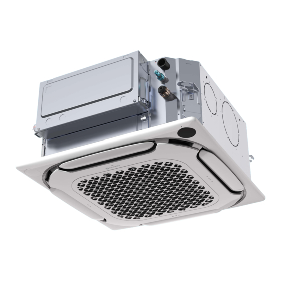
- Page 1 COMPACT 4-WAY CASSETTE Q4AN-3-XY D15÷D63 M0Q400002-00 - 01/2024...
- Page 2 Preface Dear users, Thank you for purchasing and using our product. Please read this manual carefully before you install, use, maintain or troubleshoot this product so that you can understand and use it correctly. This manual is only applicable to the listed IDU models. For ODUs or other IDUs, please refer to the applicable installation &...
-
Page 3: Table Of Contents
Contents Safety Warning Warning Signs / 01 Safety Precautions / 01 Electric Safety Requirements / 02 Operation Precautions for Use / 03 Optimum Operation / 04 Symptoms That Are Not Faults / 05 Display Panel Description / 07 Installation Installation Precautions / 08 Accessory Installation / 14 Parts / 16 Preparations Before Installation / 17... -
Page 4: Safety Warning
Please read thoroughly and fully understand the safety Safety Warning precautions (including the signs and symbols) in this manual, and follow relevant instructions during use to prevent damage to health or property. Warning Signs Different marks are used to indicate the levels of hazard severity. Please follow the instructions and ensure safe operation. [ Danger ] Failure to observe will result in severe personal injury or death. -
Page 5: Electric Safety Requirements
Ask a professional to remove and reinstall the air conditioner. Ask a professional for maintenance and repair. [ Caution ] This appliance is not intended for use by persons (including children) with reduced physical, sensory or mental capabilities, or lack of experience and knowledge, unless they have been given supervision or instruction concerning use of the appliance by a person responsible for their safety. -
Page 6: Operation
Operation Precautions for Use [ Warning ] If the unit is not used for a long time, disconnect the main power switch. Otherwise, an accident may occur. The installation height of the air conditioner shall be at least 2.5m above the ground to avoid the following risks: 1. -
Page 7: Optimum Operation
[ Caution ] In order to use the unit normally, please use the unit by following the “Operation” in this manual. Otherwise, the internal protection or dripping of the unit may occur or the cooling and heating effect may be impacted. The room temperature should be set properly, especially when there are elderly, children, or patients in the room. -
Page 8: Operating Range
Operating range To maintain good performance, operate the air conditioner under the following temperature conditions: Indoor temperature 16-30°C Cooling operation Indoor humidity dew condensation on the surface of the IDU or generate mist-like cold air from the air outlet.) Heating operation Indoor temperature 17-30°C [ Caution ]... - Page 9 Normal Phenomenon that Are Not Air Conditioner Faults The following phenomena are normal during operation of the air conditioner. They can be solved according to the instructions below or do not need to be solved. The IDU emits white mist 1.
-
Page 10: Display Panel Description
In winter, the outdoor temperature is low, and the heating effect may be decreased 1. During the heating operation of the cooling and heating type air conditioner, the air conditioner absorbs heat from the outdoor air and releases it to heat the indoor air. This is the heat pump heating principle of the air conditioner. -
Page 11: Installation
If installed improperly, fire, electric shock, injury, or water leakage may occur. For optional accessories and accessories that are sold separately, use only the products specified by Midea. The installation of these accessories must be carried out by professionals. Improper installation may cause fire, electric shock, water leakage and other hazards. - Page 12 Before and after installation, exposing the unit to water or moisture will cause electric part short-circuit. Do not store the unit in a humid basement or expose it to rain or water. Make sure the installation base and lifting are robust and reliable; Insecure installation of the base may cause the air conditioner to drop leading to accidents.
- Page 13 Forbidden Installation Sites [ Warning ] Do not install or use the air conditioner in the following places: A place filled with mineral oil, fumes or mist, like a kitchen. Plastic parts will age and the heat exchanger will be dirty, eventually causing the air conditioner to fall or leak water.
- Page 14 Choose a site that fully complies with the following conditions and user requirements to install the air conditioning unit: Enough space for installation and maintenance. (See the right diagram.) (Unit: mm) The ceiling is level, and the structure is strong enough to Air outlet support the IDU.
- Page 15 Recommended Installation Sites Crowded places such as living rooms and offices The air outlet must not face the areas where people always stay, such as sofas and coffee tables. Instead, let the wind out from the side for enhanced comfort. Air outlets at corners can be blocked with optional accessories (which can be found in the packaging material).
-
Page 16: Product Dimensions
Product Dimensions (Unit: mm) 6-M4 6-M4 6-M4 620 (with panel) Suspender installation Hex nut (to Outer diameter of matching adjust level) A: Refrigerant piping connection joint (liquid pipe) Ceiling B: Refrigerant piping connection joint (gas pipe) Main body of air conditioner Panel Capacity 1.5~5.6kW... -
Page 17: Accessory Installation
Accessory Installation Accessories List of accessories Instation & Owner's Brass nut X 2 Cable tie X 4 Thermal insulation pipe X 2 Manual X 1 IDU Installation Instructions For use in the installation works of To tighten the water discharge Used insulation (Make sure to hand it over to... - Page 18 Cooper pipe specification(Unit: mm) Piping Liquid side Gas side Capacity 1.5~5.6kW 6.3 kW For connection of the IDU refrigerant system, it is recommended to use a soft copper tube (T2M), with the length selected Remarks according to the actual situation. Thermal insulation pipe PVC pipe The wall thickness of insulation...
-
Page 19: Parts
Parts Part Description 1 IDU 2 Panel (optional) 3 Air outlet 4 Expanded air inlet/outlet 5 Fresh air inlet/outlet 6 Liquid pipe 7 Gas pipe 8 Drainage pipe 9 *Connection wire 10 Wired controller (optional) 11 Remote controller (optional) 12 Electric control box 13 Access hole 14 *Power cable and ground wire 15 *Communication line... -
Page 20: Preparations Before Installation
Preparations Before Installation Unpacking Check Before installation, check whether the packing materials are in good condition, The red dot whether the accessories that come with the product are complete, whether the bulges air conditioner is intact, whether the surfaces of the heat exchanger and other Sealing parts are worn. - Page 21 Cut a hole with the size of 590mm x 590mm according to the outline of the mounting cardboard. (Unit: mm) Shape cutting of the mounting cardboard 378±1 530±1 (suspender distance) 575±1 (IDU size) 590 (ceiling opening dimension) [ Caution ] Align the center of the ceiling box with that of the main body of the air conditioner.
-
Page 22: Idu Installation
If necessary, cut out the required openings for installation on the ceiling (where there is an existing ceiling). For the dimensions of ceiling openings, refer to the following figure. (Unit: mm) Connect to water outlet Connect to refrigerant piping (liquid side) Connect to refrigerant piping (gas side) Ceiling... - Page 23 Refer to the following table on installation using the lifting bolts. With steel frame Occasion of concrete slab Use embedded bolts and pull bolts Directly set and use an angle steel for support. Lifting bolts Lifting bolts Angle steel for support IDU Installation [ Caution ]...
- Page 24 Please confirm the installation hook position according to the installation hook holes in the four corners of the mounting cardboard. position, and then embed expansion hooks. b. During installation, make the concave surface of the mounting hook face the expansion hook, determine the appropriate length of the mounting hook according to the ceiling height, and cut off the excess part.
- Page 25 Fresh air flange Flange connecting screws (6 PCS.) [ Warning ] Make sure the IDU master unit is level: Please use a spirit level or a transparent rubber hose filled with water to correct the level of the IDU; otherwise, it will cause water leakage. The IDU is equipped with a built-in drain pump and a water level switch.
-
Page 26: Panel Installation
Main body of air conditioner Mounting cardboard (Accessories) Carry out installation as described above (Point 3 of Existing Ceiling installation). Remove the mounting cardboard. [ Note ] Make sure the IDU master unit is level: Please use a spirit level or a transparent rubber hose filled with water to correct the level of the IDU, otherwise it will cause water leakage. -
Page 27: Install The Panel
Install the panel. Drain side Bolts and washers Make sure the two hooks are well secured. Panel hook (two) Tighten the screws under the panel hooks until the thickness of the sealing sponges 1 and 2 between the IDU and the panel outlet is reduced to about 4-6mm. - Page 28 [ Caution ] Improper screw tightening may cause the failure shown in the figure below. After tightening the screws, if there is still a gap between the ceiling and the panel, the height of the IDU must be readjusted. If the lift level of the IDU and the drainage pipes are not affected, you can remove the panel and readjust the height of the IDU.
-
Page 29: Refrigerant Connecting Piping Installation
Refrigerant Connecting Piping Installation Length and level difference requirements for the pipe connections of IDU and ODU When connecting different ODUs, the length and level difference requirements for the pipe connections are different. For details, please follow the installation instructions of the ODU. [ Warning ] During installation of the connecting pipes, do not allow air, dust, and other debris to penetrate the piping system, and make sure the interior of the pipes is dry. -
Page 30: Pipe Connection
Steps of pipe connection Connect the IDU first, then connect the ODU. Before tightening the flare nut, apply refrigeration oil on the outer surface of the pipe flare and the conical surface of the connection nut (you must use refrigeration oil compatible with the refrigerant for this model), and tighten it by hand for 3 to 4 turns. - Page 31 Nitrogen Displacement Before welding the refrigerant connecting piping, carry out nitrogen replacement first, or fill the refrigerant piping with nitrogen during welding, and finally connect it to the IDU using the pipe socket. [ Warning ] When it is necessary to fill the piping with nitrogen during welding, the pressure must be controlled to 0.02MPa with a pressure relief valve.
-
Page 32: Air Discharge
Pipe size (mm) Tightening torque [ N.m (kgf.cm)] [ Note ] According to the installation conditions, excessive torque will damage the pipe socket, and too small torque may cause air leakage due to loose screw tightening. Refer to the table above to determine the tightening torque. Refrigerant piping fixing Angle iron brackets or round steel hangers should be used for fixing. -
Page 33: Drainage Pipe Installation
Drainage Pipe Installation [ Caution ] Before installation of the condensate pipeline, determine its direction and elevation to avoid intersection with other pipelines to ensure that the slope is smooth and straight. The highest point of the drainage pipe should be provided with a discharge port to ensure the smooth discharge of condensate water, and the discharge port must face downwards to prevent dirt from entering the pipe. - Page 34 The connection between the two ends of the drainage pipes and the connection of the water pump outlet only need to be fastened with a cable tie, together with PVC/rubber adhesives. Pay attention to the instructions for use of the adhesives to prevent continuous corrosion to the EPDM rubber. Use hard PVC adhesives for connecting to other water piping.
- Page 35 The end of the drainage pipe must be more than 50mm above the ground or from the base of the water discharge slot. In addition, do not submerge it in water. To discharge the condensed water directly into a ditch, the water discharge pipe must bend upwards to form a U-shaped water plug to stop the odour from entering the room via the water discharge pipe.
- Page 36 Water Discharge Test Before the test, make sure that the water discharge pipeline is smooth, and check that each connection is sealed properly. Conduct the water discharge test in a new room before the ceiling is paved. The drainage pipe can be made of PVC pipe (outer diameter: 25mm). Based on the actual installation circumstance, users can purchase pipes with appropriate length from a sales agent or the local after-sales service center, or purchase directly from the market.
-
Page 37: Electrical Connection
Electrical Connection [ Warning ] The power supply must be cut off before any electrical work is carried out. Do not operate when the power is on; otherwise, it may cause serious personal injury. Installation, inspection or maintenance operations must be completed by professional technicians; All parts and materials must comply with the relevant regulations of the local country. -
Page 38: Electrical Characteristics
Electrical characteristics Air conditioner Power supply Fan motor Frequency Voltage Power Capacity (Hz) 1.5kW 0.46 0.37 2.2kW 0.46 0.37 2.8kW 0.54 0.43 3.6kW 0.54 0.43 4.5kW 0.61 0.49 50/60 220~240 5.6kW 0.65 0.52 6.3kW 0.81 0.65 Description MCA: minimum circuit current MFA: maximum fuse current FLA: full load current Diameter selection (minimum value) - Page 39 Wiring Open the IDU's electric control box cover. ① Remove the two screws at the positions shown in the figure; ② Pull out the bottom end of the electric control box cover horizontally for a distance; ③ Take out the electric control box cover downwards. Screw (two) Connect the strong current wires (power cable, alarm signal output wire, strong current sterilization wire, and ground wire) and weak current wires (communication line, ground wire, remote switch connection wire, free...
- Page 40 Power Cable Connection (1) Power cable connection of single unit The power supply terminal of the IDU is fixed on the main board, the power cable is connected to the power supply terminal with the bit number "CN1" on the main board. The fire and neutral wires are connected according to the main board logos "L"...
- Page 41 (2) Power cable connection of a single unit Select Easycom communication which has the function of valve shut-off upon power-off. In such case, the IDUs can be powered independently, as shown in the figure below: Circuit breaker Circuit breaker Circuit breaker IDU 1 IDU 10 IDU 11...
- Page 42 Communication line connection (1) Selection of communication line diameter (wire diameter unit: mm One controller to One-to-more one IDU (centralized (Two controllers Function IDU and ODU communication controller) to one IDU) Communication Communication Easycom communication Easycom communication X1/X2 D1D2 Item (with the function of valve (without the function of valve communication...
- Page 43 When there are both V8 IDU and non-V8 IDU in a system, only P/Q communication can be selected for IDU and ODU is required to connect "P" "Q", and "E". M1/M2 communication can achieve valve shut-off upon power-off (that is, if some IDUs in the system are powered off, the bus power supply can continue to control the valve and other IDUs in the system can keep stable operation).
- Page 44 ③ Communication between indoor and outdoor units Easycom communication (separate power supply for indoor units) Single set: Easycom communication is a new indoor and outdoor unit communication technology. In case of separate power supply for indoor units, the communication line of a wire diameter of 2X1.5 mm2 is required, in order to enable the function of power-down control valve of indoor units.
- Page 45 [Caution] In case the total distance is ≤200m and the total number of indoor units is ≤10, and the main outdoor unit supply power to the control valve. If the total distance is >200m or the total number of internal units is >10, an additional repeater is needed to increase the bus voltage.
- Page 46 System: Easycom communication line of both outdoor and indoor units without the function of pow- er-down control valve has a total length of up to 2000m, supporting any topological connection. The following figure indicates the hand-in-hand connection: Power supply of indoor unit Communication line Circuit breaker Power cord...
- Page 47 PQE communication (uniform power supply for indoor unit) In the case of non-V8 indoor unit in the same refrigerant system, it needs to be connected to "P", "Q" and "E" for PQE communication. Single set: The communication line of PQE shall be shielded wire and the shielding layer shall be effec- tively grounded, and shall be connected to the terminal block with the mainboard tag No.
- Page 48 [Caution] When PQ(E) is used for communication, the indoor unit shall be uniformly powered. The communication can only be PQ(E) or Easycom. To realize the function of power-down control valve of the indoor unit, the Easycom communication must be used; The PQ(E) communication line must be shielded wires, and other wires may affect the normal communi- cation between the indoor and outdoor units.
- Page 49 (6) D1D2 communication line connection (limited to ODU and system configuration) Realizing one-to-more and two-to-more functions of the IDU wired controller through D1D2 communication D1D2 communication is 485 communication. The one-to-more and two-to-more functions of the IDU wired controller can be realized through D1D2 communication, as shown in the figure: D1D2 D1D2 D1D2...
- Page 50 (7) External board connection (limited to ODU and system configuration) The external board is a connection module outside the main board, including a display panel, a function module adapter board, and optional free function modules 1 and 2. Display connection The display is connected to the main control board through a 4-core communication line, and is connected to the "CN30"...
- Page 51 [ Caution ] For the function introduction of the function module adapter board, free function module 1, and free function module 2, please refer to the function module manual. (8) Alarm signal output, strong current sterilization connection (customized function) The alarm signal output and strong current sterilization power supply terminals are fixed on the main board, the alarm signal output and strong current sterilization modules are connected to the power supply terminal whose bit number is "CN22"...
-
Page 52: Application Control
(10) Reclose the electric control box cover Straighten the connecting wires in order and lay it flat, and close the electric control box cover again. [ Caution ] Do not cover the electric control box during power-on. When covering the electric control box, arrange the cables carefully and do not clip the connecting wires on the electric control box cover. - Page 53 Main Error Code Error Subcode Error Code Display Duplicate IDU address code Display IDU and ODU communication failure Display Master-slave wired controller communication failure Only the spot check interface is visible Communication failure between IDU main control board and fan module Display Communication failure between IDU and Wifi Kit Display...
- Page 54 Main Error Code Error Subcode Error Code Display Main board power-off - IDU main control board power-off Display Mode conflict failure - V6 protocol Display Leak inside 1# electronic expansion valve Only the spot check interface is visible Leak inside 2# electronic expansion valve Only the spot check interface is visible [ Caution ] Only the ODU model and the IDU configuration (including the wired controller and display) match can the error codes...
-
Page 55: Test Run
Constant speed mode It is necessary to use the bi-directional communication wired controller to set the unit external static pressure parameters to overcome the air outlet resistance. The steps are as follows: 1. 1. In the main page, hold " "... - Page 56 Test Run Before test run, make sure that IDUs and ODU are properly installed. The piping is correct, and the refrigerant piping system has been checked for leakage. Piping length, and the amount of refrigerant charged have been recorded. The wiring is correct and firm without virtual connection phenomenon. Ground wires have been properly connected. The voltage of the power supply is the same as the rated voltage of the air conditioner.
-
Page 57: Inspection Items After Installation
Inspection Items after Installation To ensure a comfortable indoor environment, please read the following installation points carefully and confirm whether Pass Check item Inspection contents or not Whether the IDUs and ODUs are securely installed Air conditioner falls, vibrates, and makes noise Whether the installation of the IDU has been completed The unit does not work properly or parts are burnt out Whether a leak test has been performed... -
Page 58: Cleaning, Maintenance And After-Sales Service
Cleaning, Maintenance and After-Sales Service Safety Warning [ Warning ] For safety reasons, always turn off the air conditioner and turn off the power before cleaning the air conditioner. Do not disassemble or repair the air conditioner by yourself; otherwise, it may cause fire or other dangers. Only professional service personnel can carry out the maintenance. - Page 59 Procedure diagram Remove the air inlet grille. Press the grille clamp with two fingers at the same time, and pull out the air inlet grille downwards. Flip the grille clamp to the center. Remove the filter. [ Note ] Only professionals can change and disassemble the filter. Incorrect operation by yourself may result in electric shock or damage to components.
-
Page 60: Maintenance Of Conventional Parts
Clean air outlets and exterior panels Wipe the air outlet and panel with a dry cloth. If a stain is hard to remove, clean it with clean water or neutral detergent. [ Caution ] Do not use gasoline, benzene, volatile agents, decontamination powder and liquid insecticides. Otherwise, the air outlet or panel may de-color or deform. - Page 61 Maintenance of Conventional Parts Maintenance of electronic control main board Remove the main board Open the electric control box cover. Unplug the terminals on the main board and remove Remove the two screws at the positions shown in the screws at the positions shown in the figure. the figure, and pull out the bottom end of the electric control box cover horizontally for a certain distance.
- Page 62 Open the electric control box cover and untie the Remove the sealing plate assembly cable tie. Remove the screws at the position shown in the figure, remove the sealing plate assembly, and loosen the wire binding sponge at the outlet. Screw (two) Electric control box cover Screw (three)
- Page 63 Maintenance of main motor Follow the steps above to remove the rotating fan. Unplug the motor terminals on the main board. After removing the three fixing bolts of the motor, pull out the terminals according to the motor wire path. Unplug the motor wire terminals on the main board at the position shown in the figure.
-
Page 64: Evaporator Maintenance
Evaporator maintenance Unplug the corresponding terminals on the main board. Follow the steps above to remove the panel and drain pan. Remove the sealing plate assembly After removing one fixing screw, remove the evaporator fix board. Remove the evaporator hook screws and remove the Remove the fixing screws of the evaporator and the evaporator hook. -
Page 65: Water Pump Maintenance
Water pump maintenance Unplug the water pump terminal on the main board. Follow the steps above to remove the panel and drain pan. Unplug the drainage pipe. After removing the two fixing screws, the pump can be taken out for replacement or maintenance. Touch the drainage pipe clasp and unplug the Remove the fixing screws of the water pump and the drainage pipe. - Page 66 DECLARATION OF CONFORMITY UE DICHIARAZIONE DI CONFORMITÀ EU KONFORMITÄTSERKLÄRUNG UE DECLARATION DE CONFORMITE UE DECLARACIÓN DE CONFORMIDAD UE E DECLARE UNDER OUR SOLE RESPONSIBILITY THAT THE MACHINE ICHIARIAMO SOTTO LA NOSTRA SOLA RESPONSABILITÀ CHE LA MACCHINA IR ERKLÄREN EIGENVERANTWORTLICH, DASS DIE ASCHINE OUS DÉCLARONS SOUS NOTRE SEULE RESPONSABILITÉ...
- Page 67 FOR 30 YEARS WE HAVE BEEN OFFERING SOLUTIONS FOR SUSTAINABLE COMFORT AND THE WELL-BEING OF PEOPLE AND THE ENVIRONMENT www.clivet.com sales and service CLIVET SPA Via Camp Lonc 25, Z.I. Villapaiera 32032 Feltre (BL) - Italy Tel. +39 0439 3131 - Fax +39 0439 313300 info@clivet.it...
Need help?
Do you have a question about the CLIVET Q4AN-3-XY D15 and is the answer not in the manual?
Questions and answers