Automatic license plate recognition camera (72 pages)
Summary of Contents for Viewtron IP-PTZ-425
Page 1
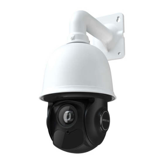
Viewtron Auto-Tracking PTZ Camera User Manual This user manual is for all Viewtron auto-tracking PTZ cameras. This includes the following models: IP-PTZ-425, IP-PTZ-440, IP-PTZ-832.
About This Manual This manual is provided for user reference only, without legal restraint. This manual is available for Viewtron PTZ cameras. Some functions introduced in the manual may be not available for some models. This content of this manual is subject to change without prior notice, and the updates will be added into the new version of this manual.
Disclaimer n With regard to the product with internet access, the use of product shall be wholly at your own risks. CCTV Camera Pros shall not be irresponsible for abnormal operation, privacy leakage or other damages resulting from cyber-attack, hacker attack, virus inspection, or other internet security risks;...
Page 4
2012/19/EU (WEEE directive): The Directive on waste electrical and electronic equipment (WEEE Directive). To improve the environmental management of WEEE, the improvement of collection, treatment and recycling of electronics at the end of their life is essential. Therefore, the product marked with this symbol must be disposed of in a responsible manner.
Contents Network Connection ......................1 LAN ......................... 1 1.1.1 Access through IP-Tool ................1 1.1.2 Directly Access through IE ................. 3 WAN ........................5 Live View .......................... 8 Camera Configuration ..................... 10 System Configuration .................... 10 3.1.1 Basic Information ..................10 3.1.2 Date and Time Configuration ..............
Network Connection 1 Network Connection System Requirement For proper operating the product, the following requirements should be met for your computer. Operating System: Windows 7 Home basic or higher CPU: 2.0GHz or higher RAM: 1G or higher Display: 1920*1080 resolution or higher (recommended) Web browser: IE (plug-in required)/ Firefox/Edge/Safari/Google Chrome It is recommended to use the latest version of these web browsers.
Page 8
Network Connection The default IP address of the camera is 192.168.226.201. ③ Double click the IP address and then the system will pop up the IE browser to connect the device. After you read the privacy statement, check and click “Already Read”. Then activate the device.
Network Connection Please enter the user name (admin) and password. Then select the stream type and language as needed. Stream Type: The plug-in free live view only supports1080P or lower resolution. The security questions should be set after you click “Login” button. It is very important for you to reset your password.
Page 10
Network Connection Gateway: 192.168.226.1 HTTP: 80 Data port: 9008 You may use the above default settings when you log in the camera for the first time. You may directly connect the camera to the computer through network cable. ① Set the IP address of the PC and make sure the network segment should be as the same as the default settings of the IP camera.
Network Connection ② Open the IE browser and enter the default address of IP-CAM and confirm. ③ Follow directions to download and install the plug-in. ④ Enter the default username and password and then enter to view. 1.2 WAN Ø Access through the router or virtual server ①...
Page 12
Network Connection ③ Go to the router’s management interface through IE browser to forward the IP address and port of the camera in the “Virtual Server”. Router Setup ④ Open the IE browser and enter its WAN IP and http port to access. Ø...
Page 13
Network Connection ③ Go to Config à Network à DDNS menu. Before you configure the DDNS, please apply for a domain name first. Please refer to DDNS Configuration for detail information. ④ Open the IE browser and enter the domain name and http port to access. Ø...
Live View 2 Live View After you log in, you will see the following window. Plug-in free live view: when the main stream is set over 1080P, only the sub stream or third stream tab can be displayed on the above interface by default. The descriptions of the icon on the live view interface are as follows: Icon Description...
Page 15
Live View Icon Description Icon Description Zoom in Region exiting indicator Zoom out Face detection indicator PTZ control Target counting indicator Face Detection SD card recording indicator : Move the cursor to view the live image in all direction after you click this button. Additionally, hold and drag the left mouse button to zoom in the live image.
Camera Configuration 3 Camera Configuration In the Webcam client, choose “Config” to go to the configuration interface. Note: Wherever applicable, click “Save” to save the settings. 3.1 System Configuration The “System configuration” includes four sub-menus: Basic Information, Date and Time, Local Config and SD Card.
Camera Configuration Select the time zone and DST as required. Note: The time zone of the camera and the computer must be the same. It is recommended to modify the time zone of the camera according to the time zone of the computer. If the time zone of the computer is modified, the current web client needs to be closed.
Camera Configuration 3.1.4 Storage Go to Config à System à Storage to go to the interface as shown below. l SD Card Management Click “Format” to format the SD card. All data will be cleared by clicking this button. Click “Eject” to stop writing data to SD card. Then the SD card can be ejected safely. Snapshot Quota: Set the capacity proportion of captured pictures on the SD card.
Camera Configuration Weekly schedule Set the alarm time from Monday to Sunday for a single week. Each day is divided in one hour increments. Green means scheduled. Blank means unscheduled. “Add”: Add the schedule for a special day. Drag the mouse to set the time on the timeline. “Erase”: Delete the schedule.
Camera Configuration Set the format, resolution and quality of the image saved on the SD card and the snapshot interval and quantity and the timing snapshot here. Snapshot Quantity: The number you set here is the maximum quantity of snapshots. The actual quantity of snapshots may be less than this number.
Page 21
Camera Configuration Brightness: Set the brightness level of the camera’s image. Contrast: Set the color difference between the brightest and darkest parts. Hue: Set the total color degree of the image. Saturation: Set the degree of color purity. The purer the color, the brighter the image is. Sharpness: Set the resolution level of the image plane and the sharpness level of the image edge.
Page 22
Camera Configuration of the image in the darkest area will be seen clearly. Antiflicker: Off: disables the anti-flicker function. This is used mostly in outdoor installations. 50Hz: reduces flicker in 50Hz lighting conditions. 60Hz: reduces flicker in 60Hz lighting conditions. White Balance: Adjust the color temperature according to the environment automatically.
Camera Configuration Drag “ ” icons to set the time of day and night. Blue means day time and blank means night time. If the current mode of camera parameters is set to schedule, the image configuration mode will automatically switch between day and night according to the schedule. 3.2.2 Video / Audio Configuration Go to Image à...
Camera Configuration Video Compression: MJPEG, H264+, H264, H265 or H265+ can be optional. MJPEG is not available for main stream. If H.265/H.265+is chosen, make sure the client system is able to decode H.265/H.265+. Compared to H.265, H.265+ saves more storage space with the same maximum bitrate in most scenes.
Camera Configuration Set time stamp, device name, device status language, OSD content and picture overlap here. After enabling the corresponding display and entering the content, drag them to change their position. Then click “Save” to save the settings. Show Azimuth: Show the PTZ moving direction on the live view interface. Show Run Status: Show the PTZ control status on the live view interface.
Camera Configuration To delete mask area: 1. Select the mask area in the mask area list. 2. Click “Delete” to delete this mask area. 3.3 PTZ Configuration 3.3.1 PTZ and Password Setting l PTZ Setting Go to Config à PTZ à Setting. This will let you see the following submenu. In this submenu, PTZ flip, PTZ flip, language, auto logout time can be set.
Camera Configuration 3.3.2 Restore It includes the function of reset and clear. Reset: Restore the camera state and active menu to the factory default settings but do not clear those parameters such as preset, cruise. Clear: Restore the camera to the factory default settings. 3.3.3 PTZ Function PTZ function includes preset setup, cruise setup, group setup, trace setup, task setup, alarm setup, home position setup and so on.
Page 28
Camera Configuration ② Enter the ID and preset name as needed. Then click “OK”. ③ Set the position of the preset by clicking the direction buttons. Then click “Save Position”. After that, click “Call” to call the preset. Cruise Setup In this interface, by programming presets in cruise list in advance, the system will keep calling those presets at the set time in sequence when executing cruise command so that non-stop monitoring between multiple important positions can be achieved.
Page 29
Camera Configuration ④ Click “Start” to run the added cruise. The camera will automatically keep running according to the cruise you set until new command is received. ⑤ Click “Stop” to stop running the cruise. Group Setup 8 cruises can be set in a group. Click “Add Cruise”...
Page 30
Camera Configuration Click “Add” and then set the trace by clicking the direction/zoom/focus buttons. Each trace can record up to 180s. If the time exceeds 180s, the system will automatically save the operation data and return to the previous menu. In addition, 360 commands can be recorded for each trace at most.
Page 31
Camera Configuration ① Click “Create” and then set the start time and the end time. ② Select the function and number. Then click “Add”. ③ After all tasks are added, click “OK” to save the settings. ④ The tasks will be automatically executed in chronological order by enabling “Run”. Alarm Setup 【Alarm Type】: Set the alarm enter type to be Normally Opened (N.O.) or Normally Closed (N.C.) according to the sensor type.
Camera Configuration 【Alarm Trigger】 : Call the preset/cruise/trace/random scanning/boundary scanning you need. When the first alarm input happens, the camera will automatically switch to this preset/cruise/trace/ random scanning/boundary scanning to monitor. 【Alarm Over】:Call the preset/cruise/trace/random scanning/boundary scanning you need. When the alarm trigger is over, the camera will automatically switch to this preset/cruise/trace/random scanning/boundary scanning to monitor.
Page 33
Camera Configuration 1. Check “Enable” check box to activate motion based alarms. If unchecked, the camera will not send out any signals to trigger motion-based recording to the NVR or CMS, even if there is motion in the video. Alarm Holding Time: it refers to the time that the alarm extends for after an alarm ends. For instance, if the alarm holding time is set to 20 seconds, once the camera detects a motion, it will go to alarm and would not detect any other motion in 20 seconds.
Camera Configuration 2. Set motion detection area and sensitivity. Click the “Area and Sensitivity” tab to go to the interface as shown below. Move the “Sensitivity” scroll bar to set the sensitivity. Higher sensitivity value means that motion will be triggered more easily. Select “Add”...
Page 35
Camera Configuration When there are some errors in writing SD card, the corresponding alarms will be triggered. 1. Go to Config à Alarm à Exception Alarm à SD Card Error as shown below. 2. Click “Enable” and set the alarm holding time. 3.
Camera Configuration 2. Click “Enable” and set the alarm holding time. 3. Trigger alarm out. When the camera is disconnected, the system will trigger the alarm out. Note: This function is only available for some models. 3.4.3 Alarm Input Only some models support this function. If your device doesn’t support it, please skip the following instructions.
Camera Configuration triggered. (Please set the warning voice first. See Audio Alarm for details). Note: Only some models support audio alarm function. If your device doesn’t support this function, please skip the instruction of “Trigger Audio Alarm”. Trigger Light Alarm: If selected, the light of the camera will turn on or flash when the sensor alarm is triggered.
Camera Configuration Day/Night Switch Linkage: Having selected this mode, select the alarm type and then choose to open or close alarm out when the camera switches to day mode or night mode. Timing: Select the alarm type. Then click “Add” and drag the mouse on the timeline to set the schedule of alarm out;...
Camera Configuration 3.4.6 Audio Alarm Only some models support this function. If your device doesn’t support this function, please skip the following instructions. Go to Alarm à Audio Alarm interface as shown below. 1. Select the warning voice. For some models, you can customize the voice. Choose “Customize”, click “Browse”...
Camera Configuration Set the record audio volume and then click “Start” to start recording your voice. Click “Upload” to upload your customized voice. Note: Only some models support voice record and you must log in the camera by the web browser with the plug-in, or voice record is not available.
Page 41
Camera Configuration PTZ Tracking Priority: if this mode is selected, in smart tracking mode, you cannot control PTZ by clicking the buttons on the PTZ control panel in the live view interface. Manual PTZ Control Priority: if this mode is selected, in smart tracking mode, you can control PTZ by clicking the buttons on the PTZ control panel in the live view interface and then the camera will immediately stop the tracking action.
Camera Configuration to enable PTZ control. After that, please remember to lock the PTZ, or object tracking will not take effect. b. After the smart tracking is enabled and the home position is locked, preset 89 will be generated as the smart tracking home position by default. Please DO NOT delete preset 89, or the PTZ will not go back to the home position after finishing tracking.
Camera Configuration Cameras should be installed on stable surfaces, as vibrations can affect the accuracy of detection. Avoid pointing the camera at the reflective surfaces (like shiny floors, mirrors, glass, lake surfaces and so on). Avoid places that are narrow or have too much shadowing. Avoid scenario where the object’s color is similar to the background color.
Camera Configuration Abnormal Color Detection: Alarms will be triggered if the image is abnormal because of color deviation. 2. Set the alarm holding time and alarm trigger options. The setup steps are the same as motion detection. Please refer to motion detection chapter for details. 3.
Page 45
Camera Configuration Detection Configuration: 1. Enable line crossing detection and select the snapshot type and the detection target. Save Original Picture to SD Card: If it is enabled, the detected original pictures will be captured and saved to the SD card when the targets cross the alarm line. Save Target Picture to SD Card: If it is enabled, the detected target cutout pictures will be captured and saved to the SD card when the targets cross the alarm line.
Page 46
Camera Configuration crossing detection is enabled. 2. Set the alarm holding time. 3. Set alarm trigger options. Alarm Out: If selected, this would trigger an external relay output that is connected to the camera on detecting a target crossing the alarm line. Trigger Audio Alarm: If selected, the warning voice will be uttered when the sensor alarm is triggered.
Camera Configuration Direction:A<->B, A->B and A<-B optional. This indicates the direction of someone or a vehicle crossing over the alarm line. A<->B: Alarms will be triggered when someone or a vehicle crosses over the alarm line from B to A or from A to B. A->B: Alarms will be triggered when someone or a vehicle crosses over the alarm line from A to B.
Page 48
Camera Configuration Detection Configuration Enable region intrusion detection, select the snapshot type and the detection target and set the alarm holding time and alarm trigger options. The detection setup steps are the same as line crossing detection. Please refer to the detection configuration of line crossing detection for details.
Camera Configuration 2. Set the alarm area number on the right side. Up to 4 alarm areas can be added. 3. Set the detection area by clicking the buttons of area ① and then click “Lock” to lock the area. Note: The PTZ will not be controlled if you click “Lock”...
Page 50
Camera Configuration 2. Enable target counting by line and select the snapshot type and the detection target. Detection Target: Select the target to calculate. Human, motor vehicle and motorcycle/bicycle can be selected. Staying Threshold: When the targets (human/vehicle) staying in the specified area exceed the threshold, alarms will be triggered.
Page 51
Camera Configuration Set the alarm line number and direction. Only one alarm line can be added. Direction:A->B and A<-B can be optional. The direction of the arrow is entrance. Statistics: If enabled, you can see the statistical information in the live view interface. If disabled, the statistical information will not be displayed in the live view interface.
Camera Configuration 7. View the statistical information of target counting by line. Click “Statistics” to enter the following interface. Select the report type. Daily report, weekly report, monthly report and annual report are selectable. Select the count type. Enter or leave can be optional. Select the start time and then click “Count”.
Page 53
Camera Configuration 2. Enable the face detection function. Save Source Information to SD Card: if checked, the whole picture will be saved to the local PC or SD card when detecting a face. Save Face Information to SD Card: if checked, the captured face picture will be saved to the local PC or SD card when detecting a face.
Page 54
Camera Configuration 5. Face database management: click “Face Database Management” tab. This will enter the following interface. There are four ways to add face pictures. ① Adding face pictures one by one Click to pop up an adding user box. Then click to select a face picture saved on the local PC.
Page 55
Camera Configuration Similarity threshold: When the similarity of the captured face picture and the face picture added into the face database exceeds the similarity threshold, alarms will be triggered. Push Stranger: Push the comparison alarm information of the stranger. After it is enabled, the comparison information of the stranger will be shown on the left comparison area of the live interface.
Page 56
Camera Configuration same target once every 5 seconds until the target disappears in the detected area. Proximity Priority Comparison: When several persons are in the recognition area at the same time, the person closer to the camera is recognized first. Comparison in free time: When the processor is busy, the comparison of the current detected person will not be performed immediately (for example, there is not enough time for the processor to perform all comparisons, because so many people are detected at the same time).
Camera Configuration l Add captured face pictures to the face database Click a captured picture in area ①. This will bring a face picture adding box. Fill out the relevant information and click “Entry” to add this face picture. 3.6 Network Configuration 3.6.1 TCP/IPv4 Go to ConfigàNetworkàTCP/IP interface as shown below.
Camera Configuration Either method of network connection can be used. If PPPoE is used to connect internet, the camera will get a dynamic WAN IP address. This IP address will change frequently. To be notified, the IP change notification function can be used. Click “IP Change Notification Config”...
Camera Configuration Persistent Connection Port: The port is used for a persistent connection of the third-party platform to push smart data, like face pictures. WebSocket Port: Communication protocol port for plug-in free preview. 3.6.3 Server Configuration This function is mainly used for connecting network video management system. 1.
Camera Configuration Note: when adding the device to the third-party platform with ONVIF/RTSP protocol, please use the onvif user in the above interface. 3.6.5 DDNS Configuration If the camera is set up with a DHCP connection, DDNS should be set for the internet. 1.
Camera Configuration Create domain name. After the domain name is successfully applied for, the domain name will be listed as below. 3. Enter the username, password, domain you apply for in the DDNS configuration interface. 4. Click “Save” to save the settings. 3.6.6 SNMP To get camera status, parameters and alarm information and remotely manage the camera, the SNMP function can be used.
Camera Configuration 2. Check the corresponding version checkbox (Enable SNMPv1, Enable SNMPv2, Enable SNMPv3) according to the version of the SNMP software that will be used. 3. Set the values for “Read SNMP Community”, “Write SNMP Community”, “Trap Address”, “Trap Port” and so on. Please make sure the settings are the same as that of the SNMP software. Note: Please use the different version in accordance with the security level you required.
Camera Configuration To use this function, the camera shall be connected to a switch supporting 802.1x protocol. The switch can be reckoned as an authentication system to identify the device in a local network. If the camera connected to the network interface of the switch has passed the authentication of the switch, it can be accessed via the local network.
Camera Configuration Audio: Having entered the main/sub stream in a VLC player, the video and audio will play automatically. If “Allow anonymous login…” is checked, there is no need to enter the username and password to view the video. If “auto start” is enabled, the multicast received data should be added into a VLC player to play the video.
Camera Configuration 3.6.11 E-mail If you need to trigger Email when an alarm happens or IP address is changed, please set the Email here first. Go to Config à Network à Email. Sender Address: sender’s e-mail address. User name and password: sender’s user name and password (you don’t have to enter the username and password if “Anonymous Login”...
Page 66
Camera Configuration 2. Click “Add” to add the information of the FTP. After that, click “Save” to save the settings. Server Name: The name of the FTP server. Server Address: The IP address or domain name of the FTP. Upload Path: The directory where files will be uploaded to. Port: The port of the FTP server.
Camera Configuration File Name Event Type IP address change MOTION Motion Detection SENSOR Sensor Alarm TRIPWIRE Line Crossing Detection PERIMETER Region Intrusion Detection Video Exception Face Detection AOIENTRY Region Entrance AOILEAVE Region Exiting PASSLINECOUNT Target Counting by Line SDFULL SD Full SDERROR SD Error TXT file content:...
Camera Configuration includes target tracing coordinates, target features, the captured original/target image (like the captured face picture, motor vehicle picture) and so on. 3.6.14 HTTPS HTTPs provides authentication of the web site and protects user privacy. Go to Config à Network à HTTPS as shown below. There is a certificate installed by default as shown above.
Camera Configuration Then click “OK” to save the settings. * Click “Create a certificate request” to enter the following interface. Click “Create” to create the certificate request. Then download the certificate request and submit it to the trusted certificate authority for signature. After receiving the signed certificate, install the certificate to the device.
Page 70
Camera Configuration Add user: 1. Click the “Add” button to pop up the following textbox. 2. Enter user name in the “User Name” textbox. 3. Enter the password in the “Password” and “Confirm Password” textbox. Please set the password according to the requirement of the password security level (Go to Config à...
Camera Configuration 3. Enter the old password of the user in the “Old Password” text box. 4. Enter the new password in the “New password” and “Confirm Password” text box. 5. Select the user permissions for advanced or normal user. 6.
Camera Configuration An administrator user can kick out all the other users (including other administrators). 3.7.3 Block and Allow Lists Go to Config à Security à Block and Allow Lists as shown below. The setup steps are as follows: Check the “Enable address filtering” check box. Select “Block/Allow the following address”, IPv4/IPv6 and then enter IP address in the address box and click the “Add”...
Camera Configuration Please set the password level and expiration time as needed. Password Level: Weak, Medium or Strong. Weak level: Numbers, special characters, upper or lower case letters can be used. You can choose one of them or any combination of them when setting the password. Medium Level: 8~16 characters, including at least two of the following categories: numbers, special characters, upper case letters and lower case letters.
Camera Configuration Import & Export Settings Configuration settings of the camera can be exported form a camera into another camera. 1. Click “Browse” to select the save path for import or export information on the PC. 2. Click the “Import Setting” or “Export Setting” button. Default Settings Click the “Load Default”...
Page 75
Camera Configuration 2. Select the main type, sub type, start and end time. 3. Click “Query” to view the operation log. 4. Click “Export” to export the operation log.
Search 4 Playback 4.1 Image Search Click Search to go to the interface as shown below. Images that are saved on the SD card can be found here. Note: When using the plug-in free browser, the local images cannot be searched. l Local Image Search Choose “Picture”—“Local”.
Page 77
Search Note: When using the plug-in free browser, the local images cannot be searched. l SD Card Image Search Choose “Picture”—“SD Card”. Set time: Select date and choose the start and end time. Choose the alarm events at the bottom of the interface. Click to search the images.
Search 4.2 Video Search 4.2.1 Local Video Search Click Search to go to the interface as shown below. Videos were recorded locally to the PC can be played in this interface. Note: When using the plug-in free browser, the local videos cannot be searched. Choose “Record”—“Local”.
Search Icon Description Icon Description Play button. After pausing the video, click this button Pause button to continue playing. Stop button Speed down Speed up Watermark display Enable / disable audio; drag the slider to adjust the volume after enabling audio. Note: When using the plug-in free browser, the local videos cannot be searched.
Page 80
Search Note: cannot be displayed in the above interface via the plug-in free browser. Additionally, for plug-in free playback, playback mode switch (balanced/real-time/fluent mode) and downloading functions are not supported too. The time table can be shown in 24H/12H/2H/1H format by clicking the corresponding buttons.
Face Match Result Search 5 Face Match Result Search Click “Face Log” tab to go to the face recognition result search interface. Set the start time and end time and click “Search” to view the face recognition result. A photo of each recognized face is marked with a colored bar. The red color of the bar means no comparison result.
Page 82
Q&A 6 Q & A 1. Q: I forget the password. How can I do? Reset the system to the factory default setting or contact the dealer. Default IP: 192.168.226.201 User name: admin Password: 123456 2. Q:The devices can’t connect through IE browser. Why? ①...
Page 83
Q&A Fig 4-1 Fig 4-2 ④ Then click OK to finish setup. Other plug-ins or anti-virus blocks ActiveX. Please uninstall or close them. 5. Q:Why does the device fail to sound? The audio input device is not connected. Please connect and try again. The audio function is not enabled at the corresponding channel.
Need help?
Do you have a question about the IP-PTZ-425 and is the answer not in the manual?
Questions and answers