
Related Manuals for The Loudspeaker Kit M6S


Summary of Contents for The Loudspeaker Kit M6S
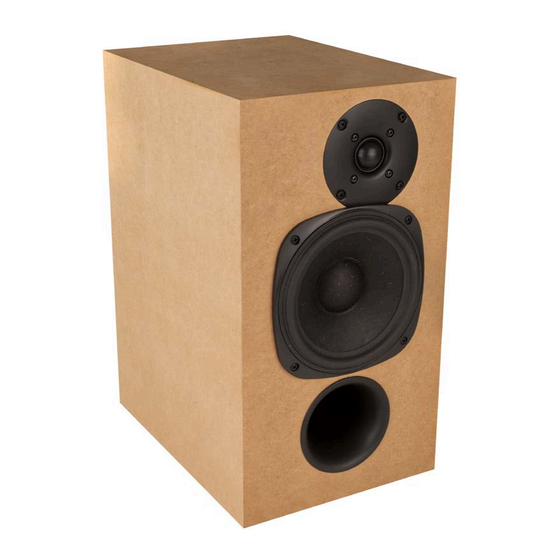
- Page 1 M6S Assembly Instructions Designed and manufactured in Australia by The Loudspeaker Kit www.theloudspeakerkit.com Email: sales@theloudspeakerkit.com...
-
Page 2: Easier Assembly With Mitres
Assembly manual You will need: • Phillips head screwdriver • Woodworking glue • Damp cloth • Good quality masking tape • Ratchet tie down strap (optional) • Brick or other weight (optional) Preparation Lay the contents of the box out and check you have everything you need to complete the kit (see parts list on back page). - Page 3 Assembly manual Masking tape We recommend avoiding cheap masking tape, which tends to break when applied under tension. If you aren’t using the weight and ratchet strap, you are relying on the masking tape along to apply pressure to the join as the glue sets. Lay out the rear panel and apply masking tape up as shown.
- Page 4 Assembly manual Apply a glue bead to all four joins between the rear and adjacent panels. This first bead of glue should be applied to the bottom of the mitre. Then apply a second bead in the middle of the mitre.
- Page 5 Assembly manual Confirm that the glue adequately covers the entire surface of the joins by folding up each pair of panels. Check the glue covers the entire surface and add more glue where necessary. Now apply glue to the joins between top, bottom and side panels. Fold up the first pair again, wipe excess glue then firmly press the panels together as you hold them in place with masking tape.
- Page 6 Assembly manual Apply one thick glue bead to the mitres on the front baffle. Confirm the amount of glue by pressing into position. The entire join should be covered in glue – apply more glue where necessary. The photo above shows a second bead being applied after checking the glue cover.
- Page 7 Assembly manual An optional step for improved clamping pressure is to secure top, bottom and side panels with a tie down ratchet strap. Avoid damage to the surface of the MDF by placing cardboard strips under the straps at all four corners. Be careful to avoid applying excessive force, which can damage the corners of the MDF or even collapse the cabinet.
- Page 8 Assembly manual Drying time Typical wood glues can achieve moderate strength in as little as 30 minutes. If you are using PVA glue then a good indicator that it has set is the transparency. PVA becomes transparent once set. Ideally it’s best to leave the enclosure clamped over night before moving on to assembly or finishing.
-
Page 9: Installing The Crossover Board
Assembly manual Installing the crossover board There are three sets of cables: • Input terminals: located near the larger inductor on the end of the board. • Tweeter output: easily identified by the white cable (HI+ HI -) • Woofer output: black cable next to the tweeter outputs (LOW+ LOW-) The board is fixed in place with 4 short button head self tapping screws. -
Page 10: Installing Terminals
Assembly manual As shown above, driver cutouts provide access to fix the passive crossover board in place. Using the shorter screws, fix the board in place with a Phillips head screwdriver. Avoid over tightening. Ensure the board is oriented so the inputs with the shortest cable pair are near the terminal cut out. - Page 11 Assembly manual M6S section diagram Acoustic lining The acoustic lining provided with the kit covers all internal cabinet walls. Each of the smaller pieces (A) cover the top and bottom walls. The larger pieces (B) are folded to cover side and rear walls.
- Page 12 Assembly manual The diagram above shows the arrangement of the acoustic lining. As shown on the photo on the previous page, an opening in the lining must be made with a blade, to allow the wire looms for tweeter and mids to pass through. Avoid blocking the port Since the input terminal is located behind the terminus of the port, the lugs on the terminal should be bent towards the location of the crossover board.
-
Page 13: Installing Drivers
Assembly manual Installing drivers We recommend using a Phillips head screwdriver, as some powered drivers are more likely to cause damage if the head slips off the screw head. Impact drivers should be avoided. If using a powered driver, it’s best to use one which has a clutch, so that once the screws are adequately tightened, the driver will not over-tighten. - Page 14 Assembly manual Tweeter Find the white wire loom for the tweeter and push the connectors onto the driver tabs. Caution: tweeter terminals are fragile – observe instructions on the previous page about how to safely connect the cable without causing damage Insert the provided screws into position and tighten with a Phillips head screwdriver as shown below.
- Page 15 Assembly manual Woofers Find the white wire loom for each woofer and push the connectors onto the driver tabs. Caution: Observe instructions in this manual regarding how to safely connect the cable without causing damage. Insert the provided screws into position and tighten with a Phillips head screwdriver as shown below.
-
Page 16: Grille Assembly
Assembly manual Grille assembly Masking On the backside of the grille, you will notice a trench inset from the edges. This is the cut line and defines the area where the cloth will be glued to the frame. The area inside this line needs to be masked, so the spray adhesive is applied only to the strip around the edge. - Page 17 Assembly manual When you’ve finished spraying, turn the can upside down and spray briefly until you notice the amount of spray reduces. Usually after about one second, the paint stops but the solvent continues. This cleans out the nozzle and avoids blocking next time you want to continue using it.
- Page 18 Assembly manual Above you can see the wrinkles across the grille which indicate sufficient tension has been applied. Now press the grille cloth to the frame on the third side, avoiding contact around the corner. Then finally, press the cloth to the final side of the frame. In this step, all wrinkles from the tension should be gone.
- Page 19 Assembly manual Keeping the tension on the cloth, transfer the fabric to one hand, so that your other hand is free. Press out any wrinkles with your finger as shown below. If there are some wrinkles you can’t press out this way, the adhesive provides some work time during which you can lift up the cloth and press it down again.
- Page 20 Assembly manual Trim the cloth Now you can use your thumbnail to find the cut line. Pressing your nail into the trench, score all the way around. This helps to confirm that you’ve effectively avoided wrinkles. Then with a sharp blade, slowly and carefully cut away the grille cloth, using the trench as a guide. Tips for a better cut: •...
-
Page 21: Parts List
Assembly manual Parts List: • 2 x 6” Woofers (SB16PFC25-08) • 2 x 1” Tweeters (SB26ST-C0005) • 2 x Crossover Networks • 2 x Round input Terminals • 12 x Panels CNC machined 18mm MDF panels • 2 x CNC machined 12mm MDF grille frame •...
Need help?
Do you have a question about the M6S and is the answer not in the manual?
Questions and answers