Table of Contents
Advertisement
Quick Links
Advertisement
Table of Contents

Subscribe to Our Youtube Channel
Related Manuals for Shel lab SGO3


Summary of Contents for Shel lab SGO3
- Page 1 GRAVITY OVENS 110 – 120 Voltage Installation - Operation Manual SGO3...
- Page 2 Pictured on the cover: SGO3 Warning: This product contains chemicals, including triglycidyl isocyanurate, known to the State of California to cause cancer as well as birth defects or other reproductive harm. For more information, go to www.P65Warnings.ca.gov. ¡Advertencia! Este producto contiene sustancias químicas, incluido el triglicidil isocianurato, que el estado de California sabe que causa cáncer, así...
- Page 3 SLG322 The Part ID denotes the specific build type of the model. SHEL LAB is a brand of Sheldon Manufacturing, INC., an ISO-certified manufacturer. Safety Certifications These units are CUE listed by TÜV SÜD as gravity ovens for professional, industrial, or educational use where the preparation or testing of materials is done at an ambient air pressure range of 22.14 –...
- Page 4 The units have been tested to the following requirements: CAN/CSA C22.2 No. 61010-1:2012 CAN/CSA C22.2 No. 61010-2-010:2015 UL 61010-1:2012 UL 61010-2-010:2015 EN 61010-1:2010 EN 61010-2-010:2014 P a g e...
-
Page 5: Table Of Contents
TABLE OF CONTENTS INTRODUCTION ..........................7 Read this Manual ............................7 Safety Considerations and Requirements ....................7 Contacting Assistance ..........................8 Manufacturing Warranty ........................... 8 Engineering Improvements ........................8 Reference Sensor Device .......................... 9 RECEIVING YOUR UNIT ........................11 Inspect the Shipment ..........................11 Orientation Photos .......................... - Page 6 This page left blank. P a g e...
-
Page 7: Introduction
INTRODUCTION Thank you for purchasing a SHEL LAB oven. We know you have many choices in today’s competitive marketplace when it comes to constant temperature equipment. We appreciate you choosing ours. We stand behind our products and will be here if you need us. -
Page 8: Contacting Assistance
Therefore, some changes, modifications, and improvements may not be covered in this manual. If your unit’s operating characteristics or appearance differs from those described in this manual, please contact your SHEL LAB dealer or customer service representative for assistance. -
Page 9: Reference Sensor Device
INTRODUCTION EFERENCE EN SOR EVI CE Must be purchased separately A reference sensor device is required for calibrating the unit temperature display. Reference devices must meet the following standards: Accurate to at least 1°C • Temperature Reference The device should be regularly calibrated, preferably by a third party. Temperature Probes Use a digital device with wire thermocouple probes that can be introduced into the oven chamber through the unit access port. - Page 10 INTRODUCTION 10 | P a g e...
-
Page 11: Receiving Your Unit
Included Accessories Model Shelves Shelf Clips Leveling Feet Power Cord SGO3 8. A high-temperature access port stopper ships installed in the port located on the back of the oven. Verify the presence of the stopper. 11 | P a g e... -
Page 12: Orientation Photos
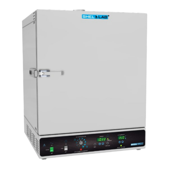
RECEIVING YOUR UNIT R I ENTATI ON HOTOS SGO3 Exhaust Port with Sliding Dampener Chamber Gasket Door Latch Chamber Door Handle Access Port Control Panel Oven Chamber Main Temperature and OTL Sensor Probes 12 | P a g e... - Page 13 RECEIVING YOUR UNIT SGO3 - Unit Back Exhaust Vent Access Port (Stopper Installed) Power Cord Inlet with Fuse 13 | P a g e...
-
Page 14: Recording Data Plate Information
RECEIVING YOUR UNIT ECORDI NG LATE NFOR M ATI ON Record the unit model number, serial number, part number, and part ID below for future reference. Tech Support needs this information to provide accurate help during support calls and emails. •... -
Page 15: Installation
INSTALLATION N STALLATI ON ROCEDURE HECK LI ST For installing the oven in a new workspace. Pre-Installation Check that the required workspace ambient conditions for the unit are met, page Unit dimensions may be found on page 43 • ... -
Page 16: Required Ambient Conditions
(152mm) 12” (305mm) Door Swing SGO3: 27” (686mm) 24 inches (610mm) of headspace clearance is required between the exhaust vent and any • overhead cover or partition. 12 inches (305mm) of vertical headspace clearance suffices if the oven exhaust is vented from the workspace through a duct or other channeling. -
Page 17: Power Source Requirements
Power Source: The wall power outlet must meet the power requirements listed on the unit data plate. These units are intended for 110 – 120 VAC, 50/60 Hz applications at the following amperages: SGO3 14.0 Amps Supplied voltage must not vary more than 10% from the data plate rating. -
Page 18: Lifting And Handling
INSTALLATION I FTI NG AND ANDLI NG The unit is heavy. Use appropriate lifting devices that are sufficiently rated for the unit weight. Follow the guidelines below when lifting the unit: Lift the unit only from its bottom surface. • Doors, handles, and knobs are not adequate for lifting or stabilization. -
Page 19: Install The Oven
INSTALLATION N STALL THE Place the unit in a workspace location that meets the criteria discussed in the previous entries of the Installation section. EI ONI ZED AND I STI LLED ATER Do not use deionized water to clean the unit. Use of deionized water may corrode metal surfaces and voids the warranty. -
Page 20: Shelving Installation
INSTALLATION HELVI NG N STALLATI ON 1. Install 4 clips for each shelf in the slots located on the sides of the chamber interior. a. Squeeze each clip. b. Insert the top tabs first, then the bottom tabs using a rocking motion. 1. -
Page 21: Graphic Symbols
GRAPHIC SYMBOLS The unit is provided with multiple graphic symbols on its exterior. The symbols identify hazards and the functions of the adjustable components, as well as important notes in the user manual. Symbol Definition Consult the user manual Consulter le manuel d'utilisation Temperature display Indique l'affichage de la température Over Temperature Limit system... - Page 22 GRAPHIC SYMBOLS Symbol Definition Indicates the timer Indique le minuterie Start or Stop the Timer Lancer ou arrêter le minuteur Reset the Timer Réinitialisation de la Minuterie 22 | P a g e...
-
Page 23: Control Panel Overview
CONTROL PANEL OVERVIEW Control Panel Power Switch When in the ON ( I ) position, the switch illuminates and the oven heats to the currently programmed temperature setpoint. Timer Switch The black Timer Switch controls power to the timer system. When this switch is in the ON position, the ovens stop heating, the SET TIMER display illuminates, and the user may launch a timed, steady-state heating profile running at the current temperature setpoint. - Page 24 CONTROL PANEL OVERVIEW Timer Display and Control Pad The SET TIMER display shows the duration of the currently programmed heating profile, or a flashing duration adjustment mode, or the countdown of an active profile to 0. The “//” RESET button is used to place the Timer display in its adjustable duration mode, and then to scroll through the duration time parameters.
-
Page 25: Operation
OPERATION Safe operation of the unit is dependent on the actions and behavior of the unit operators. Operating personnel must read and understand the Operating Precautions in this section prior to operating the unit. The operators must follow these instructions to prevent injuries and to safeguard their health, environment, and the materials being treated in the unit, as well as to prevent damage to the unit. - Page 26 Warning: The vent dampers may be hot to the touch. These areas are marked with Hot Surface labels. Proper PPE should be employed to minimize risk to burn. Avertissement: Les clapets d'aération peuvent être chauds au toucher. Ces zones sont marqués avec des étiquettes de Surface chaude.
-
Page 27: Theory Of Operation
P ER ATI ON Heating When powered, the SGO3 oven chamber heats to and then maintains the currently programmed temperature setpoint. The oven comes from the factory with a temperature setpoint of “OFF”. The setpoint may be adjusted by the end-user using the Set Temperature controls. - Page 28 OPERATION Timed Heating Profile The oven is provided with a Timer subsystem. When set, it runs the oven in a steady-state heating profile at the current temperature setpoint for 1 minute up to 99 hours, 59 minutes. Allow the oven to heat to the profile temperature prior to launching a profile.
-
Page 29: Put The Oven Into Operation
OPERATION Note: The oven may produce light smoking during its first use above 150°C as the remnants of a protective oil coating burn off the heating element. UT THE VEN I N TO P ERATI ON Carry out the following steps and procedures to put the oven into operation after installing it in a new workspace environment. -
Page 30: Set The Temperature Setpoint
OPERATION ET THE EM P ER ATUR E ETP OI NT Set the oven to your application temperature. Turn the OTL dial clockwise to its maximum position, if not already set to max. This prevents the heating cutoff system from interfering with this •... -
Page 31: Set The Over Temperature Limit
OPERATION Note: Test the OTL system at least once per year to verify its functionality ET THE EM P ERATUR E I M I T This procedure sets the Over Temperature Limit heating cutoff to approximately 5˚C above the current chamber temperature. - Page 32 OPERATION ETTI NG THE I M ER This procedure enters a heating profile duration in the Timer system. When launched, the profile runs the oven for the duration at the present temperature setpoint. Turn on the Timer System Set Timer The oven will cease heating •...
- Page 33 OPERATION Set Timer (Continued) Set the Tens-of-Minute parameter 1 Hour, 51 Minutes Adjust Advance to the Minutes parameter The flashing decimal point advances to • between the third and fourth numbers. This saves the new Tens-of-Minutes • Press parameter setting. Minutes Selected Set the Minutes parameter 1 Hour, 55 Minutes...
-
Page 34: Setting The Timer
OPERATION AUNCHI NG A EATI NG R OFI LE Allow the oven to come up to temperature prior to launching a profile. See the Setting the Timer procedure on page 32 for how to set the length of the profile. Note: While the Timer system is on, the oven will not heat unless a profile is running. -
Page 35: High Exterior Temperatures
OPERATION I GH XTER I OR EM P ERATURES Note: Allow the oven to cool or use appropriate PPE and tools when adjusting the chamber gasket seating. If the chamber gasket comes out of alignment, oven chamber air may be drawn into the insulating baffle spaces. - Page 36 OPERATION This page is blank. 36 | P a g e...
-
Page 37: User Maintenance
USER MAINTENANCE Warning: Prior to maintenance or service on this unit, disconnect the power feed from the power supply. Avertissement: Avant d'effectuer toute maintenance ou entretien de cet appareil, débrancher le cordon secteur de la source d'alimentation. LEAN I NG AND I SI NFECTI NG If a hazardous material or substance has spilled in the unit, immediately initiate your site’s Hazardous Material Spill Containment protocol. -
Page 38: Gaskets And Chamber Integrity
LECTRI CAL OM P ON EN TS Electrical components do not require maintenance. If the unit fails to operate as specified, please contact your SHEL LAB distributor or Technical Support for assistance. 38 | P a g e... -
Page 39: Calibrate The Temperature Display
USER MAINTENANCE ALI B RATE THE EM P ERATUR E I SP LAY Note: Please see the Reference Sensor Device entry on page 9 for the device requirements. Temperature calibrations match the temperature display to the actual air temperature inside the unit chamber. - Page 40 USER MAINTENANCE 7. Heat up and stabilization period The oven chamber temperature must be stable to perform an accurate calibration. • The temperature is considered stabilized when the oven chamber has operated at your calibration • temperature for at least 1 hour with no fluctuations greater than the specified temperature stability of the oven (see the Unit Specifications chapter).
- Page 41 USER MAINTENANCE Calibration continued Place the oven in temperature calibration mode. a. Press and hold both the UP and DOWN arrow buttons simultaneously for approximately 5 seconds. The Temperature Display will show the letters “C O”, • then begin flashing the current temperature value. Note: If an arrow key is not pressed for 5 seconds, the Current Temp.
- Page 42 USER MAINTENANCE Calibration continued Compare the reference device reading with the chamber display again. Reference Device If the reference device and the chamber temperature • display readings are the same, or the difference falls within the range of your protocol, the unit is now calibrated for temperature.
-
Page 43: Unit Specifications
All indications are average values, typical for units produced in the series. We reserve the right to alter technical specifications at all times. EI GHT Model Shipping SGO3 146 lb / 66 kg 126.5 lb / 57.4 kg I M EN SI ON S By Inches Model Exterior W ×... -
Page 44: Shelf Capacity By Weight
SGO3 *50 lb / 22.6 kg with weight evenly distributed across the shelf. ***200 lb / 91.0 kg total load for the SGO3 shelves. Exceeding this limit risks damaging the chamber liner. EM P ERATURE All temperature performance specifications are given for wire shelves in the chamber and using the recommended vent setting of 1/3 open. -
Page 45: Power
UNIT SPECIFICATIONS Time to Temperature: From an ambient temperature of 20°C. Model Heat Up to 80°C Heat Up to 150°C Heat Up to 306°C SGO3 7 Minutes 23 Minutes 95 Minutes Recovery Time: From a 30-second door opening. Model Recovery to 80°C Recovery to 150°... - Page 46 UNIT SPECIFICATIONS 46 | P a g e...
-
Page 47: Parts List
Description Parts Number Power Cord 125 volt, Adjustable Leveling 15Amp, 9ft 5 in (2.86m) Foot NEMA 5-15P 2700512 1800510 Chamber Gasket, SGO3, sold by 1.5 feet, Port Stopper, High requires 7.5ft (2.3 Temperature meters) 7750572 3450767 (1.5ft) Fuse, T16A 250V... - Page 48 P.O. Box 627 Cornelius, OR 97113 support@sheldonmfg.com sheldonmanufacturing.com 1-800-322-4897 (503) 640-3000 FAX: 503 640-1366...
Need help?
Do you have a question about the SGO3 and is the answer not in the manual?
Questions and answers