
Related Manuals for Shel lab SRI3


Summary of Contents for Shel lab SRI3
- Page 1 BOD INCUBATOR 110 – 120 Voltage / 220 – 240 Voltage Installation - Operation Manual SRI3 SRI3-2...
- Page 2 WARNING: Never use this unit for the growth, cultivation, incubation or storage of fruit flies (drosophila melanogaster). This unit is not designed for use with fruit flies. Improper use of this unit, including use with fruit flies, will void any warranty. Other units are specifically manufactured for fruit fly applications, and you should consult your dealer or the manufacturer in order to identify another model suitable for your application.
- Page 3 INCUBATOR SRI3 110 – 120 Voltage SRI3-2 220 – 240 Voltage Part Number (Manual): 4861574 Revision: February 12, 2018 These units are compliant with the following standards for use within an ambient air pressure range of 22.14 – 31.3 inHg (75 – 106 kPa), with no flammable, volatile, or combustible materials being heated.
-
Page 4: Table Of Contents
TABLE OF CONTENTS INTRODUCTION ................................ 5 Read this Manual ..................................5 Safety Considerations and Requirements ........................5 Contacting Assistance ................................6 Engineering Improvements..............................6 Reference Sensor Device ..............................7 RECEIVING YOUR UNIT ............................9 Inspect the Shipment ................................9 Orientation Photo ................................. 10 Recording Data Plate Information ............................ -
Page 5: Introduction
INTRODUCTION Thank you for purchasing a SHEL LAB product. We know you have many choices in today’s competitive marketplace when it comes to constant temperature equipment. We appreciate you choosing ours. We stand behind our products and will be here for you if you need us. -
Page 6: Contacting Assistance
Therefore, some changes, modifications, and improvements may not be covered in this manual. If your unit’s operating characteristics or appearance differs from those described in this manual, please contact your SHEL LAB dealer or customer service representative for assistance. -
Page 7: Reference Sensor Device
INTRODUCTION EFERENCE ENSOR EVICE Optional Must be purchased separately A reference sensor device is required for calibrating the unit temperature display. Reference devices must meet the following standards: Accurate to at least 0.1°C • Temperature The device should be regularly calibrated, preferably by a third party. Reference Temperature Probe Use a digital device with a wire thermocouple probe that can be introduced into the unit chamber... - Page 8 INTRODUCTION P a g e...
-
Page 9: Receiving Your Unit
RECEIVING YOUR UNIT NSPECT THE HIPMENT When a unit leaves the factory, safe delivery becomes the responsibility of the carrier. • Damage sustained during transit is not covered by the manufacturing defect warranty. • Save the shipping carton until you are certain that the unit and its accessories function •... -
Page 10: Orientation Photo
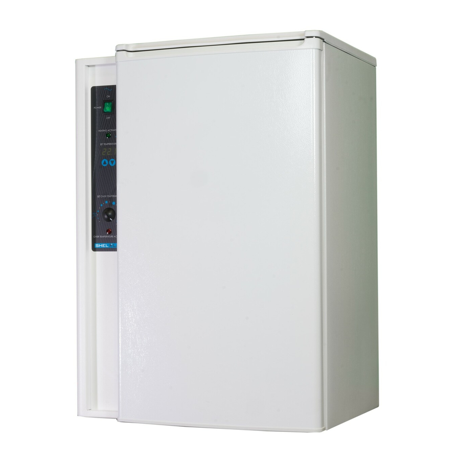
RECEIVING YOUR UNIT RIENTATION HOTO Figure 1: SRI3/SRI3-2 Control Panel Chamber Door Temperature Probe Incubation Chamber Door Gasket Wire Shelf, 1 of 2 10 | P a g e... -
Page 11: Recording Data Plate Information
RECEIVING YOUR UNIT ECORDING LATE NFORMATION The data plate contains the unit model number and serial number. Tech Support will need this information during any support call. Record it below for future reference. • The data plate is located near the power cord on the back of the unit. Model Number Serial Number 11 |... - Page 12 RECEIVING YOUR UNIT 12 | P a g e...
-
Page 13: Installation
INSTALLATION NSTALLATION HECKLIST For installing the unit in a new workspace location. Pre-Installation Check that the required ambient conditions and ventilation spacing for the incubator are met, page 14. Unit dimensions may be found on page 39. • Check that a suitable electrical outlet and power supply is present, page 15. -
Page 14: Required Ambient Conditions
INSTALLATION EQUIRED MBIENT ONDITIONS When selecting a location to install the unit, consider all environmental conditions that can adversely impact its temperature performance. These include: Proximity to ovens, autoclaves, and any device that produces significant radiant heat • Heating and cooling vents or other sources of fast-moving air currents •... -
Page 15: Power Source Requirements
The power source for the unit must match the voltage and the amperage requirements listed on the unit data plate. These units are intended for 110 - 120V 50/60 Hz (SRI3) or 220 – 240V 50/60 Hz (SRI3-2) applications at the following amperages:... -
Page 16: Lifting And Handling
INSTALLATION IFTING AND ANDLING The unit is heavy. Use appropriate lifting devices that are sufficiently rated for these loads. Follow these guidelines when lifting the unit. Lift the unit only from its bottom surface. • Doors, handles, and knobs are not adequate for lifting or stabilization. •... -
Page 17: Adjust Shelves
INSTALLATION DJUST HELVES Note: The form factor of the shelves may vary slightly by year of production. The unit ships with its shelves installed in the incubation chamber. Tape, foam, and other packing dunnage is used to secure the shelves during transit and prevent damage to the chamber interior. Remove all shipping materials from the shelving. -
Page 18: Deionized And Distilled Water
INSTALLATION EIONIZED AND ISTILLED ATER Do not use deionized water to clean the chamber even if it is readily available in your laboratory environment. Use of deionized water may corrode metal surfaces and voids the warranty. Sheldon Manufacturing recommends the use of distilled water in the resistance range of 50K Ohm/cm to 1M Ohm/cm, or a conductivity range of 20.0 uS/cm to 1.0 uS/cm, for cleaning applications. -
Page 19: Graphic Symbols
GRAPHIC SYMBOLS Your incubator comes provided with graphic symbols on its exterior surfaces. These identify hazards and the function of the adjustable components, as well as important notes in the user manual. Symbol Definition Consult the user manual. Consulter le manuel d'utilisation Temperature display Indique l'affichage de la température Over Temperature Limit system... - Page 20 GRAPHIC SYMBOLS 20 | P a g e...
-
Page 21: Control Panel Overview
CONTROL PANEL OVERVIEW Power Switch The power switch controls all power to the unit and its systems. Power is supplied when the switch is illuminated and in the ( I ) ON position. Heating Activated The Heating indicator light illuminates when power is routed to the incubator heating element. - Page 22 CONTROL PANEL OVERVIEW 22 | P a g e...
-
Page 23: Operation
OPERATION HEORY OF PERATION Refrigerated incubators are engineered to provide constant temperature incubation environments suitable for BOD applications. The unit can obtain a stable, uniform temperature in its chamber, ranging from 0°C up to 40°C. Achieving and Maintaining the Temperature Set Point When the unit is powered, its refrigeration compressor runs continuously. -
Page 24: Put The Incubator Into Operation
OPERATION UT THE NCUBATOR INTO PERATION Putting the incubator into operation in a new workspace environment requires an 8-hour period for the unit to come up to and stabilize at temperature prior to loading the incubation chamber with samples. During this period the incubator must be powered with the chamber door closed. Allowing time for stabilization helps protect samples. -
Page 25: Set The Temperature Set Point
OPERATION ET THE EMPERATURE OINT The incubator comes from the factory with a set point of 20°C. Perform the steps below to change the set point to your process or application temperature. Set Temperature Set Point Turn the OTL dial clockwise to its max setting, if not already set at max. -
Page 26: Set The Over Temperature Limit
OPERATION Note: Test the OTL system at least once per year for functionality. ET THE EMPERATURE IMIT The incubator must be operating at your incubation application temperature and must be stable for at least 1 hour prior to setting the OTL. Allow the unit to operate for at least 8 hours prior to setting the OTL when first placing it into operation. -
Page 27: Loading Samples
UTLET Outlets The SRI3 is provided with 2 power outlets inside the chamber. Do not attach powered equipment drawing more than 1 amp from both outlets. The SRI3-2 is provided with 1 power outlet inside the chamber. Do not attach powered equipment drawing more than 1 amp from the outlet. -
Page 28: Condensation And The Dew Point
OPERATION ONDENSATION AND THE OINT Relative humidity inside the incubation chamber should never be allowed to exceed 80% at 25°C. Exceeding this threshold will likely result in condensation, possible leaks around the incubator, and may cause corrosion damage if allowed to continue for any significant length of time. Condensation takes place whenever the humidity level in the incubation chamber reaches the dew point. -
Page 29: User Maintenance
USER MAINTENANCE Warning: Disconnect the unit from its power supply prior to performing maintenance or services. Avertissement: Débranchez cet appareil de son alimentation électrique avant d'effectuer la maintenance ou les services. LEANING AND ISINFECTING If a hazardous material or substance has spilled in the unit chamber, immediately initiate your site Hazardous Material Spill Containment protocol. -
Page 30: Minimizing Contamination Exposure
USER MAINTENANCE Disinfecting For maximum effectiveness, disinfection procedures are typically performed after cleaning. Keep the following points in mind when disinfecting the unit. Turn off and disconnect the unit to safeguard against electrical hazards. • Disinfect the unit chamber using commercially available disinfectants that are non-corrosive, •... -
Page 31: Refrigeration And Defrosting
USER MAINTENANCE EFRIGERATION AND EFROSTING The refrigeration compressors of most home refrigerators run periodically in order to maintain an average chamber temperature centered on the thermostat setting. This results in temperature oscillations of up to 2° or 3°C and reflects the fact that affordable refrigeration compressors cannot provide the high degree of temperature stability needed for laboratory applications —... - Page 32 USER MAINTENANCE Factors in Ice Build Up Incubators used for biologic oxygen demand studies and other closed-container applications will generally require infrequent and very short defrost runtimes. However, runtimes may be prolonged and occur more frequently if the incubator is used in a high humidity environment with the door opened several times a day or left open for prolonged periods.
- Page 33 USER MAINTENANCE Turning Off the Automatic Defrost Deactivating the defrost thermostat will result in ice accumulation and a gradual loss of cooling efficiency. Incubators used for BOD and other closed-container applications with the defrost thermostat turned off will likely require manual defrosting every 6 months. Units with open sources of water evaporation and the defrost thermostat shut off will require manual defrosting every 2 to 3 months.
-
Page 34: Calibrate The Temperature Display
USER MAINTENANCE ALIBRATE THE EMPERATURE DISPLAY Note: Performing a temperature display calibration requires a temperature reference device. Please see the Reference Sensor Devices entry on page 7 for device requirements. Temperature calibrations are performed to match the incubator temperature display to the actual air temperature in the incubation chamber. - Page 35 USER MAINTENANCE 5. Temperature Stabilization The incubator air temperature must stabilize in order to perform an accurate calibration. Allow the incubator to operate undisturbed with the door shut for at least 8 hours when first • putting the unit into operation in a new environment. To be considered stabilized, the incubator chamber must operate at your calibration •...
- Page 36 USER MAINTENANCE Temperature Calibration Continued Place the display in temperature calibration mode. a. Press and hold both the UP and DOWN temperature buttons simultaneously for approximately 5 seconds. b. Release the buttons when the temperature display shows the letters “C O”. The display will begin flashing the current temperature display value.
- Page 37 USER MAINTENANCE Temperature Calibration Continued Reference Device Compare the reference device reading with the chamber temperature display again. If the reference device and the chamber temperature display • readings are the same or the difference falls within the range of your protocol, the incubator is now calibrated for temperature.
- Page 38 USER MAINTENANCE 38 | P a g e...
-
Page 39: Unit Specifications
UNIT SPECIFICATIONS The SRI3 Incubator is a 115 voltage unit; the SRI3-2 is a 230 voltage unit. Please refer to the unit data plate for individual electrical specifications. Technical data specified applies to units with standard equipment at an ambient temperature of 25°C and at nominal voltage. -
Page 40: Shelf Capacity By Weight
UNIT SPECIFICATIONS HELF APACITY BY EIGHT Model Per Shelf Total SRI3 10.0 lb / 4.5 kg 20.0 lb / 9.0 kg SRI3-2 10.0 lb / 4.5 kg 20.0 lb / 9.0 kg EMPERATURE Model Range Uniformity Stability ± 0.5° ± 0.2°C SRI3 Ambient 0°C to 45°C... -
Page 41: Parts List
PARTS LIST Ordering Parts and Consumables If you have the Part Number for an item, you may order it directly from Sheldon Manufacturing by calling 1-800-322-4897 extension 3. If you are uncertain that you have the correct Part Number, or if you need that specific item, please contact Sheldon Technical Support for help at 1-800-322-4897 extension 4 or (503) 640-3000. - Page 42 P.O. Box 627 Cornelius, OR 97113 support@sheldonmfg.com sheldonmanufacturing.com 1-800-322-4897 (503) 640-3000 FAX: 503 640-1366...
Need help?
Do you have a question about the SRI3 and is the answer not in the manual?
Questions and answers