
Related Manuals for Endress+Hauser IO-Link Liquiphant FTL43


Summary of Contents for Endress+Hauser IO-Link Liquiphant FTL43
- Page 1 Products Solutions Services BA02309F/00/EN/02.23-00 71646084 2023-10-31 Valid as of version 01.00.zz (Device firmware) Operating Instructions Liquiphant FTL43 IO-Link Vibronic Point level switch for liquids...
- Page 2 The manufacturer reserves the right to modify technical data without prior notice. The Endress+Hauser sales organization will supply you with current information and updates to these instructions. Endress+Hauser...
-
Page 3: Table Of Contents
IO-Link information ....26 Index ........46 Endress+Hauser... -
Page 4: About This Document
In the IEC 61131-9 standard, IO-Link is standardized under the description "Single-drop digital communication interface for small sensors and actuators (SDCI)". 1.2.4 Symbols for certain types of Information Permitted: Procedures, processes or actions that are permitted. Forbidden: Procedures, processes or actions that are forbidden. Endress+Hauser... -
Page 5: List Of Abbreviations
For an overview of the scope of the associated Technical Documentation, refer to the following: • Device Viewer (www.endress.com/deviceviewer): Enter the serial number from the nameplate • Endress+Hauser Operations app: Enter serial number from nameplate or scan matrix code on nameplate. Registered trademarks Apple®... -
Page 6: Basic Safety Instructions
Liquiphant FTL43 IO-Link Bluetooth® The Bluetooth® word mark and logos are registered trademarks owned by the Bluetooth SIG, Inc. and any use of such marks by Endress+Hauser is under license. Other trademarks and trade names are those of their respective owners. ®... -
Page 7: Workplace Safety
The device fulfills general safety requirements and legal requirements. It also complies with the EU directives listed in the device-specific EU Declaration of Conformity. Endress+Hauser confirms this fact by affixing the CE mark. IT security Our warranty is valid only if the product is installed and used as described in the Operating Instructions. -
Page 8: Product Description
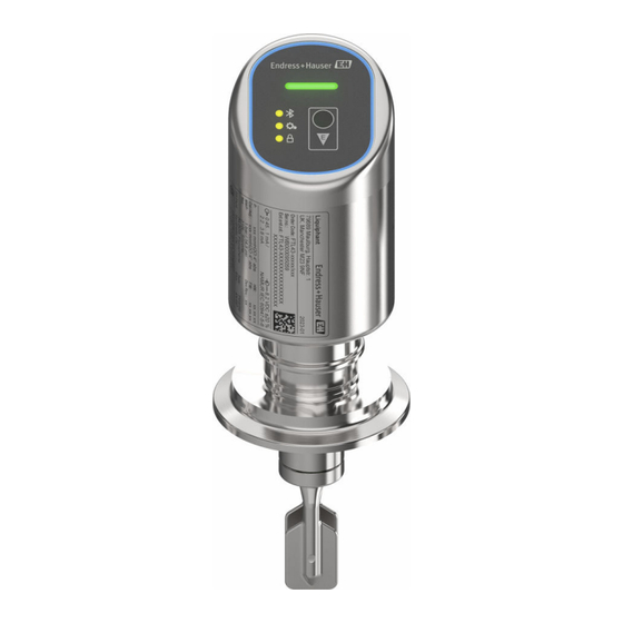
Housing with electronics module Temperature spacer, pressure-tight feedthrough (second line of defense), optional Process connection, e.g. clamp/Tri-Clamp Process connection, e.g. thread Compact probe version with tuning fork Pipe extension probe with tuning fork Short pipe version of probe with tuning fork Endress+Hauser... -
Page 9: Incoming Acceptance And Product
• Firmware version, hardware version • Approval-specific information • DataMatrix code (information about the device) Compare the data on the nameplate with your order. 4.2.2 Manufacturer address Endress+Hauser SE+Co. KG Hauptstraße 1 79689 Maulburg, Germany Place of manufacture: See nameplate. Endress+Hauser... -
Page 10: Storage And Transport
• Any orientation for compact version or version with a tube length up to approx. 500 mm (19.7 in) • Vertical orientation from above for device with long pipe • Minimum distance between the tuning fork and the tank wall or pipe wall: 10 mm (0.39 in) Endress+Hauser... -
Page 11: Mounting Requirements
Minimum distance between the tuning fork and the tank wall or pipe wall: 10 mm (0.39 in) A0037915 4 Typical switch points. Unit of measurement mm (in) Installation from above Installation from below Installation from the side Switch point Endress+Hauser... - Page 12 Installation example for a highly viscous liquid. Unit of measurement mm (in) 5.1.4 Avoid buildup • Use short installation sockets to ensure that the tuning fork projects freely into the vessel • Leave sufficient distance between the buildup expected on the tank wall and the tuning fork Endress+Hauser...
- Page 13 Allow sufficient clearance outside the tank for mounting and electrical connection. A0053359 8 Take clearance into consideration. 5.1.6 Support the device Support the device in the event of severe dynamic load. Maximum lateral loading capacity of the pipe extensions and sensors: 75 Nm (55 lbf ft). Endress+Hauser...
-
Page 14: Mounting The Device
Aligning the tuning fork using the marking The tuning fork can be aligned using the marking in such a way that the medium drains off easily and buildup is avoided. Markings on process connection: Material specification, thread designation, circle, line or double line Endress+Hauser... -
Page 15: Post-Mounting Check
• Turn by the hex bolt only, 15 to 30 Nm (11 to 22 lbf ft) • Do not turn at the housing! A0054233 13 Screwing in the device Post-mounting check Is the device undamaged (visual inspection)? Are the measuring point identification and labeling correct (visual inspection)? Endress+Hauser... -
Page 16: Electrical Connection
IEC/DIN EN 61326-1: Test level on DC power ports and input/output ports is 1 000 V line to earth. Overvoltage protection category According to IEC/DIN EN 61010-1, the device is intended for use in overvoltage protection category II networks. 6.1.5 Range of adjustment Switch points can be configured via IO-Link. Endress+Hauser... - Page 17 85 °C (185 °F). If the "1 x PNP" or "2 x PNP" configuration is used, the switch outputs can be loaded with a total of up to 200 mA over the entire temperature range. Different for switch output OUT2, for switch status OFF: I < 3.6 mA and U < 2 V and for switch status ON: voltage drop PNP: ≤ 2.5 V Endress+Hauser...
-
Page 18: Ensuring The Degree Of Protection
‣ The degree of protection only applies if the connecting cable used is specified according to the intended protection class. Post-connection check Is the device or cable undamaged (visual check)? Does the cable used comply with the requirements? Endress+Hauser... -
Page 19: Operation Options
Overview of operation options • Operation via LED indicator operating key • Operation via Bluetooth® • Operation via Endress+Hauser operating tool • Operation via IO-Link master Structure and function of the operating menu The complete operating menu is available via the operating tools (FieldCare, DeviceCare, SmartBlue) in order to make more complex settings on the device. -
Page 20: Access To Operating Menu Via Led Indicator
• LED flashing: Bluetooth connection established Trigger proof test or function test LED (4) LED (4) flashing: Proof test or function test currently running. See "Proof test function" section Keypad lock LED (5) • LED lit: Key locked • LED not lit: Key released Endress+Hauser... - Page 21 Bluetooth is enabled (Bluetooth LED is lit) or Bluetooth is disabled (Bluetooth LED goes out). 7.3.3 Proof test function For proof testing in safety instrumented systems according to WHG The status LEDs show the simulation status generated by the proof test. Endress+Hauser...
-
Page 22: Access To The Operating Menu Via The Operating Tool
FieldCare Function range FDT-based plant asset management tool from Endress+Hauser. FieldCare can configure all smart field devices in a system and helps you manage them. By using the status information, FieldCare is also a simple but effective way of checking their status and condition. - Page 23 The Field Xpert SMT70 tablet PC for device configuration enables mobile plant asset management in hazardous (Ex Zone 2) and non-hazardous areas. It is suitable for commissioning and maintenance staff. It manages Endress+Hauser and third-party field instruments with a digital communication interface and documents the progress of the work.
-
Page 24: System Integration
2 switch outputs. The status of the switch outputs (SSC), the measured value (MDC) and the Endress+Hauser-specific extended device status are transmitted via IO-Link in the form of process data. The process data are cyclically transmitted in accordance with the IO-Link Smart Sensor Profile type 4.3. -
Page 25: Reading Out And Writing Device Data (Isdu - Indexed Service Data Unit)
Device data are always exchanged acyclically and at the request of the IO-Link master. Parameter values or device statuses can be read out using the device data. All device data and parameters (Endress+Hauser and IO-Link-specific as well as system commands) can be found in the separate device parameter documentation for the device. -
Page 26: Io-Link Information
Switching on the device Once the supply voltage has been switched on, the device adopts the normal mode after a maximum of 4 s. During the start-up phase, the outputs are in the same state as when switched off. Endress+Hauser... -
Page 27: Overview Of Commissioning Options
"Basic settings" submenu • Density setting parameter • Safety function parameter • MIN option • MAX option Commissioning via additional operating tools (AMS, PDM, etc.) Download the device-specific drivers: https://www.endress.com/en/downloads For more details, see the help for the relevant operating tool. Endress+Hauser... -
Page 28: Configuring The Device
If the device is restarted within the given hysteresis, the switch output is open (0 V present at the output). 100 % SP 2 SP 1 A0054230 16 SSC, Two-point SP 2 Switch point with lower measured value SP 1 Switch point with higher measured value Inactive Active Endress+Hauser... -
Page 29: Protecting Settings From Unauthorized Access
Maintenance option switches to the Operator option as a result of this locking. The configuration can be accessed by entering the password. The password is defined under: System menu User management submenu The user role is changed from the Maintenance option to Operator option under: Endress+Hauser... -
Page 30: Operation
• The wizard can be used via the operating tools • The wizard guides the user through the entire process for creating the verification report Start Heartbeat Verification and Status Result are available via IODD. The Heartbeat Verification wizard is available via the SmartBlue app. Endress+Hauser... - Page 31 Heartbeat Verification is shown in the IODD. Heartbeat Monitoring must be configured in the operating menu of the SmartBlue app. The Heartbeat Monitoring results can be read out in the IODD via the active and last diagnosis. Documentation on the Heartbeat Technology: Endress+Hauser website: www.endress.com → Downloads.
-
Page 32: Displaying The Measured Value History
• Possible cause: The polarity of the supply voltage is wrong Remedial action: Correct the polarity 11.1.2 Error - SmartBlue operation with Bluetooth® Operation via SmartBlue is only possible on devices that have a display with Bluetooth (optionally available). Endress+Hauser... - Page 33 • Possible cause: Operator option has no authorization Remedial action: Change to the Maintenance option 11.1.3 Measures For information on measures in the case of an error message: See "Pending diagnostic messages" section. If the measures do not rectify the problem, contact your Endress+Hauser office. Endress+Hauser...
- Page 34 • The selected alarm current is used for all errors • Errors and warning messages are displayed via IO-Link • It is not possible to acknowledge errors and warnings. The relevant message disappears if the event is no longer pending Endress+Hauser...
-
Page 35: Diagnostic Information On Operating Status
Sensor electronics faulty Replace electronics Alarm Sensor connection faulty 1. Check Main to sensor Alarm connection 2. Replace electronics Sensor initialization 1. Restart device Alarm faulty 2. Contact service Diagnostic of electronic Electronics faulty 1. Restart device Alarm 2. Replace electronics Endress+Hauser... - Page 36 Current output 1 Deactivate simulation Warning simulation active Switch output 1 Deactivate switch output simulation C Warning simulation active Diagnostic event Deactivate simulation Warning simulation active Configuration Sensor 1. Check sensor configuration Warning Unit invalid 2. Check device configuration Endress+Hauser...
-
Page 37: Event Logbook
• : End of the event • Information event : Occurrence of the event provides a chronological overview of the event messages that have occurred. If the device is operated via FieldCare, the events list can be displayed via the FieldCare function "Event List". Endress+Hauser... - Page 38 I1335 Firmware changed I1397 Fieldbus: access status changed I1398 CDI: access status changed I1440 Main electronic module changed I1444 Device verification passed I1445 Device verification failed I1461 Sensor verification failed I1512 Download started I1513 Download finished I1514 Upload started Endress+Hauser...
-
Page 39: Resetting The Device
For details see the "Description of device parameters" documentation. 11.6 Device information All device information is contained in the Information submenu. Navigation: System → Information For details see the "Description of device parameters" documentation. 11.7 Firmware history 11.7.1 Version 01.00.00 Initial software Endress+Hauser... -
Page 40: Maintenance
13.1 General information 13.1.1 Repair concept The Endress+Hauser repair concept is devised in such a way that repairs can only be carried out through device replacement. 13.1.2 Replacing a device After the device is replaced, previously saved parameters can be copied to the newly installed device. -
Page 41: Disposal
• 1 = BN = brown • 2 = WT = white • 3 = BU = blue • 4 = BK = black 14.1.3 Welding neck, process adapter and flange For details, refer to TI00426F/00/EN "Weld-in adapters, process adapters and flanges". Endress+Hauser... -
Page 42: Devicecare Sfe100
14.2 DeviceCare SFE100 Configuration tool for IO-Link, HART, PROFIBUS and FOUNDATION Fieldbusfield devices DeviceCare is available for download free of charge at www.software-products.endress.com. You need to register in the Endress+Hauser software portal to download the application. Technical Information TI01134S 14.3... -
Page 43: Technical Data
200 mA. If the "1 x PNP" or "2 x PNP" configuration is used, the switch outputs can be loaded in total with up to 200 mA over the entire temperature range. Differing for switch output OUT2, for switch status OFF: I < 3.6 mA and U < 2 V and for switch status ON: voltage drop PNP: ≤ 2.5 V Endress+Hauser... -
Page 44: Environment
+150 °C (+302 °F) –40 °C (–40 °F) –40 °C (–40 °F) –40 °C (–40 °F) 15.2.2 Storage temperature –40 to +85 °C (–40 to +185 °F) 15.2.3 Operating height Up to 5 000 m (16 404 ft) above sea level Endress+Hauser... - Page 45 • Shock resistance: 30 g (18 ms) in all 3 axes 15.2.9 Electromagnetic compatibility (EMC) • Electromagnetic compatibility as per EN 61326 series and NAMUR recommendation EMC (NE21) • Maximum deviation under the effect of disturbance: < 0.5% For more details refer to the EU Declaration of Conformity. Endress+Hauser...
-
Page 46: Index
Read access ....... . 19 Repair concept ......40 Endress+Hauser... - Page 48 *71646084* 71646084 www.addresses.endress.com...
Need help?
Do you have a question about the IO-Link Liquiphant FTL43 and is the answer not in the manual?
Questions and answers