Table of Contents
Advertisement
Quick Links
Advertisement
Table of Contents

Related Manuals for Electron retracts E-Brakes


Summary of Contents for Electron retracts E-Brakes
- Page 1 www.electron-retracts.com...
-
Page 2: Table Of Contents
Contents PAGE Part A: Product info and characteristics Wiring diagram ......3 Technical Specifications ....4 Part B: Step by step connection guide Connect the brakes . -
Page 3: Wiring Diagram
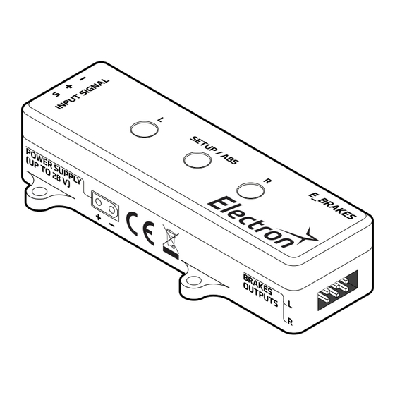
E-Brakes User manual and installation instructions BRAKES WIRING DIAGRAM LEFT BRAKE RIGHT BRAKE POWER SUPPLY (UP TO 28V) Please make sure to follow the correct polarity as indicated: Negative Positive Signal info@electron-retracts.com... -
Page 4: Technical Specifications
The shorter the wire can be, the better. The E-Brakes must be fixed to its mounting surface to avoid the wires from being disconnected while in flight. For this purpose, the case features four mounting holes for M2,5 screws. - Page 5 Because of this, the E-Brakes features a 90 seconds timer, which is triggered each time the brakes are powered. After this time has passed, the E-Brakes will automatically shut-down the brakes.
-
Page 6: Connect The Brakes
E-Brakes User manual and installation instructions Brakes CONNECT THE BRAKES LEFT BRAKE RIGHT BRAKE Please make sure to follow the correct polarity as indicated: Positive Not in use Negative info@electron-retracts.com... -
Page 7: Connect The Battery
Power CONNECT THE BATTERY Supply The E-Brakes features a XT-30u male socket for power input. A compatible female connector for the battery is provided with this device. The battery is used only to power up the brakes, while the E-Brakes itself is powered with the voltage provided by the signal input from the receiver. -
Page 8: Connect Rx Brake Input
Signal CONNECT RX BRAKE INPUT Input The E-Brakes features a JR-Servo male socket for signal input (PWM). This signal will be used to program and operate the device. Additionally, the voltage provided through this connection will be used to power up the E-Brakes. -
Page 9: Controller Setup
E-Brakes User manual and installation instructions CONTROLLER SETUP After all connections have been made, the E-Brakes needs to be programmed. In the setup, we will adjust the minimum and maximum brake force signal values. ATTENTION! Before you begin the setup, check the settings for the radio channel that will be used. -
Page 10: Enter Programming Mode
E-Brakes User manual and installation instructions Setup ENTER PROGRAMMING MODE To start the Setup, the receiver must be turned OFF. Press and hold the SETUP/ABS button, and while holding it, turn ON the receiver. The SETUP/ABS LED button should lit and blinking with a blue light. -
Page 11: Continuous Brake And Abs Modes
User manual and installation instructions Operating CONTINUOUS BRAKE AND ABS MODES The E-Brakes offers a continuous brake mode where brakes are powered without interruption, and an ABS mode with three different presets. The ABS will release and engage the brake at different ratios, to avoid wheel blocking. -
Page 12: Balance Adjustment / Compensation
BALANCE ADJUSTMENT / COMPENSATION Balance In the event of an imbalance in the brakes causes the aircraft to veer, the E-Brakes allows you to correct this deviation, by adjusting the current level individually for each output. CASE 1: THE PLANE VEERS TO THE LEFT... - Page 13 Electron Retracts S.L.U C.I.F. B-36539211 Pol. Inds. PPI-7, Parcela K, Nave B9 36475 – O Porriño (Spain)
Need help?
Do you have a question about the E-Brakes and is the answer not in the manual?
Questions and answers