Table of Contents
Advertisement
Quick Links
Advertisement
Table of Contents

Summary of Contents for Electron retracts ControlBox
- Page 1 www.electron-retracts.com...
-
Page 2: Table Of Contents
Contents PAGE Part A: Connection diagram ....3 Part B: Step by step connection Retracts connection ......5 Brakes connection . -
Page 3: Part A: Connection Diagram
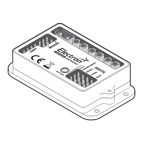
ControlBox User manual and installation instructions RETRACTS CONNECTION DIAGRAM RC BATTERY BATT MAIN RIGHT MAIN LEFT NOSE Please make sure to follow the correct polarity as indicated: BRAKES INPUTS Negative CONTROLBOX Positive Signal POWER SUPPLY The voltage of the rudder´s servo will be the same as the receiver. - Page 4 ControlBox. ORIENTATION AND PLACEMENT The ControlBox doesn’t required to be oriented towards an specific direction from your model, and it’s not mandatory for it to be placed on a flat surface. We recommend installing the ControlBox in a location that allows for the shortest possible connections with retracts and brakes.
-
Page 5: Retracts Connection
Connect the retract wires to the Retracts Gear Outputs. The are three gear outputs, indicated in one of A Main right retract the sides of the ControlBox as “Nose”,“MainL” and “MainR”, and they correspond to the nose/front retract, main/wing left and right retracts, respec- tively. -
Page 6: Brakes Connection
ControlBox User manual and installation instructions Please make sure to follow the correct polarity as indicated: Positive Not in use Negative If your landing gear system Brakes doesn’t have brakes, you can skip this step. Connect the brake wires to the Brake Outputs. -
Page 7: Steering Servo Connection
If your landing gear system doesn’t have a steering servo, you can skip this step. Connect the steering servo wire to the Rudder servo Output. We highly recommend to operate the steering servo via the ControlBox, as opposed to directly controlling the servo from the receiver. -
Page 8: Input Channels Connection
User manual and installation instructions Input INPUT CHANNELS CONNECTION Connect the radio inputs from your receiver to the ControlBox There are three PWM radio inputs. The polarity of these inputs is indicated in the ControlBox. NOTE: The voltage provided by the receiver can’t be higher than 9 V, and it should be the same on all of signal inputs. -
Page 9: Power Supply
User manual and installation instructions Power CONNECT POWER BATTERY Supply The ControlBox has a battery input (XT-30u female connector). The XT-30u female connector for the battery is provided with the landing gear set. The battery provides power to the retracts and the brakes only. Make sure to check the polarity of the battery connector when preparing your battery. -
Page 10: Part C: Set Up Controller
• Position of the center steering wheel IMPORTANT! We highly recommend to perform the programming of the ControlBox with the battery disconnected, to avoid RC BATTERY any unexpected movements of the landing gear. All that it required for the programming, are the input signals from the receiver. - Page 11 ControlBox User manual and installation instructions SET UP CONTROLLER In the example we are going to use switch 1 to control the landing gear, wheel 2 to control the brakes and controller 3 for the front wheel. MEANING OF THE FLASHING LIGHT One blink: Programming mode started, set landing gear retracted position.
-
Page 12: Enter Programming Mode
ControlBox User manual and installation instructions Set up ENTER PROGRAMMING MODE With everything connected and off, we press and hold the Control Box programming button. Without releasing the programming button, we turn on the radio receiver. Once turned on we can release the Control Box button and we will be in programming mode. -
Page 13: Set The Position Of The Brakes
ControlBox User manual and installation instructions SET THE POSITION OF THE BRAKES In this step we are going to establish minimum and the maximum force of the brake. SET MINIMUN BRAKE POSITION 6.3.1 Set the position for the brake to the minimum. -
Page 14: Position Of The Center Wheel
ControlBox User manual and installation instructions POSITION OF THE CENTER WHEEL SET POSITION OF STEER WHEEL Please notice, If your, it’s extremely important that the center position is as accurate as possible, to ensure the proper coupling of the steering mechanism. -
Page 15: Manual Operation
MANUAL OPERATION MODE The ControlBox features a manual operation mode, to deploy or retract the landing gear system. To operate the gear manually, press and hold the ControlBox button for 5 seconds. NEW! BATTERY MONITORING MEANING OF THE FLASHING LIGHT... - Page 16 Electron Retracts S.L.U C.I.F. B-36539211 Pol. Inds. PPI-7, Parcela K, Nave B9 36475 – O Porriño (Spain)


Need help?
Do you have a question about the ControlBox and is the answer not in the manual?
Questions and answers